【Cyber Command】STA Hyper-V Deployment Guide_V3.0.65 (STA V3.0.39)
Introduction Solution Overview
The rapid development of cloud computing in recent years has become a conventional bearer of information business systems. As a result, security tends to become cloud-based with the change in how the business operates today. As a security detection platform product, Stealth Threat Analysis (STA) can detect and analyze traffic in and outside the cloud to enhance security operations in the cloud environment. This document will show how to deploy and install Sangfor vSTA on Hyper-V using Windows Server 2019.
Notice:
vSTA involved in this solution is for cloud or virtualized environments instead of Bare Metal Servers (BMSs) and cannot be directly deployed on a physical server.
Compatibility List
The following table describes the platform environments supported by vSTA.
| Environment | Version | Image Type | Deployment | Traffic Collection Method (CWPP) | Traffic Collection Method (Transparent transmission of the physical switch) | Traffic Collection Method (Mirroring traffic of another VM) | Traffic Collection Method (Other) |
|---|---|---|---|---|---|---|---|
| Hyper-V | Windows Server 2019/2022 | ISO | Yes | Not supported | Supported | Supported | Unknown |
| VMware ESXi | VMware ESXi 5.0/6.0/7.0 | ISO | Yes | Not supported | Supported | Supported | Unknown |
| HCI | All standard versions (not covering all custom versions) | ISO | Yes | Not supported | Not supported | Supported (HCI 6.8.0 or later required) | Unknown |
Table 1: List of environments compatible with vSTA
Port Matrix
Hyper-V
| No. | Source Device | Source Port | Destination Device | Destination Port | Port Description | Remarks |
|---|---|---|---|---|---|---|
| 1 | STA | Any | Cyber Command | TCP-443 TCP-4430 TCP-4488 |
TCP-4430: to receive logs. TCP-4488: to update rules on Cyber Command. TCP-443: to update the version of Cyber Command. |
After vSTA installation, the default version is 3.0.39C, which can be directly upgraded to the next version. |
| 2 | Operation and maintenance terminal | Any | STA | TCP-443 | TCP-443: for web management. | After vSTA installation, the default version is 3.0.39C, which can be directly upgraded to the next version. |
| 2 | Operation and maintenance terminal | Any | Cyber Command | TCP-443 | TCP-443: for web management. | After vSTA installation, the default version is 3.0.39C, which can be directly upgraded to the next version. |
Table 2: Port matrix for vSTA on Hyper-V
Important Notes
Windows Server & Hyper-V Version
This document only supports Windows Server 2019 and Windows sever 2022 for STA deployment on Hyper-V.
VM Resource Specifications
Ensure that the resource specifications allocated for vSTA meet the requirements. For details, see Chapter 2.1 VM Resources.
Preparations Before Deployment
VM Resources
The following table describes the specific vSTA resource specifications.
Notice:
- During CPU allocation to vSTA, ensure that the number of slots in use is one or two. When more than two slots are in use, an exception will occur. For example, for 16-core CPU resources, it can use the 1×16 or 2×8 specifications.
- Configure VMs in strict accordance with the following specifications. It is common that port 443 fails to work, or data disk mounting fails due to insufficient specifications. In this case, check and confirm by yourself.
Notice:
During STA deployment in a virtualized environment, use local storage. Network storage is not supported.
vSTA VM models
The data in the following table indicates the performance of a physical machine dependent on Hyper-V where only one virtual STA is enabled. The CPU model is Intel (R) Xeon (R) Gold 5218 CPU @ 2.30GHz.
vSTA performance is highly reliable on the physical machine, and the performance may vary with the physical machine and deployment mode.
| Specification | vCPU | Memory | Storage | Network Interfaces | Application Layer Processing Capability | Remarks |
|---|---|---|---|---|---|---|
| STA-1000-v1500 | 4 cores | 4 GB | System disk: 64 GB Data disk: 128 GB |
3–6 | 250 MB | 1. Insufficient or excessive network interfaces may result in abnormal STA key services. Ensure that at least three interfaces are used. |
| STA-1000-v2100 | 4 cores | 8 GB | System disk: 64 GB Data disk: 128 GB |
3–6 | 500 MB | 1. Insufficient or excessive network interfaces may result in abnormal STA key services. Ensure that at least three interfaces are used. |
| STA-1000-v2150 | 8 cores | 8 GB | System disk: 64 GB Data disk: 256 GB |
3–6 | 750 MB | 1. Insufficient or excessive network interfaces may result in abnormal STA key services. Ensure that at least three interfaces are used. |
| STA-1000-v2200 | 8 cores | 16 GB | System disk: 64 GB Data disk: 480 GB |
3–6 | 1 GB | 1. Insufficient or excessive network interfaces may result in abnormal STA key services. Ensure that at least three interfaces are used. |
| STA-1000-v2300 | 12 cores | 8 GB | System disk: 64 GB Data disk: 480 GB |
3–6 | 1.5 GB | 1. Insufficient or excessive network interfaces may result in abnormal STA key services. Ensure that at least three interfaces are used. |
| STA-1000-v2450 | 12 cores | 16 GB | System disk: 64 GB Data disk: 480 GB |
3–6 | 2 GB | 1. Insufficient or excessive network interfaces may result in abnormal STA key services. Ensure that at least three interfaces are used. |
| STA-1000-v2600 | 16 cores | 16 GB | System disk: 64 GB Data disk: 960 GB |
3–6 | 2.5 GB | 1. Insufficient or excessive network interfaces may result in abnormal STA key services. Ensure that at least three interfaces are used. |
| STA-1000-v3100 | 20 cores | 40 GB | System disk: 64 GB Data disk: 960 GB |
3–6 | 3 GB | 1. Insufficient or excessive network interfaces may result in abnormal STA key services. Ensure that at least three interfaces are used. |
vSTA Standard ISO Image File
You need to download the vSTA 3.0.39C image file from Sangfor Community.
Sangfor Community:
https://community.sangfor.com/plugin.php?id=service:download&action=view&fid=92#/37/all
Overall Installation and Deployment
Hyper-V Deployment Scenarios
Multiple network adapters are required on the Windows server. When you deploy STA on Hyper-V, use one of the network interfaces as the management interface for communication between the virtual STA and the external system. Select another one or more network interfaces as the mirror interface(s) for traffic for virtual STA traffic auditing.
After the on-site technical colleagues perform preliminary investigation and resource preparations, the deployment can start, which includes the following three stages: bare VM creation, VM configuration, and system installation.
vSTA 3.0.39C Installation
Notice:
Ensure that the VM resource specifications prepared before installation meet expectations. The specifications include but are not limited to CPU, memory, system disks, data disks, and NICs. For details about the specifications, see Chapter 2.1 VM Resources.
Create VM
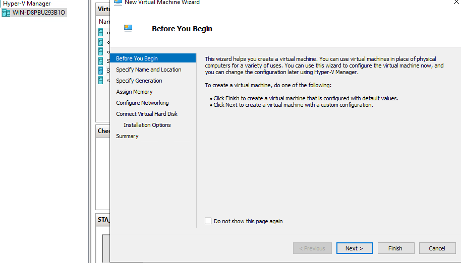
- Log in to Hyper-V Manager with the admin account and go to the Hyper-V page. Right-click the server name and choose New > Virtual Machine to enter the New Virtual Machine Wizard, as shown below.
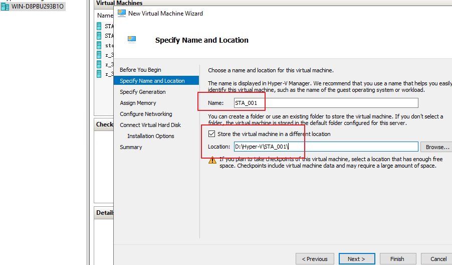
- Click Next. Set Name and Location, as shown in the following figure.
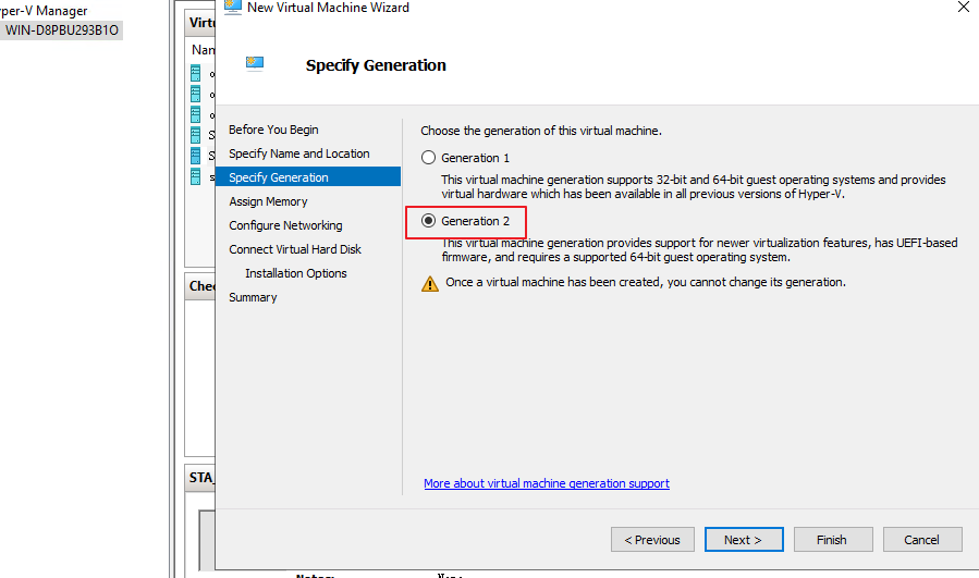
- Click Next. Choose the VM generation (Generation 2 is recommended), as shown below.
- Click Next. Set Startup memory, as shown in the following figure. For details, see the resource allocation part in Chapter 2.1 (STA with an 8-core CPU and 8 GB of memory as an example).
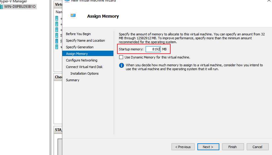
Notice:
Do not select Use Dynamic Memory for this virtual machine. Otherwise, traffic mirroring will fail.
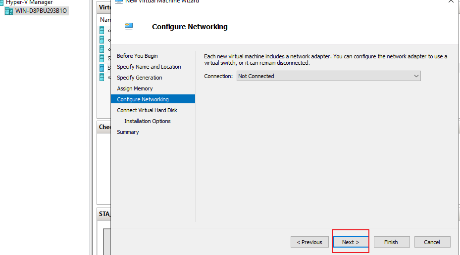
- Click Next. In the Configure Networking page that appears, click Next, as shown in the following figure. The Connection doesn’ t required to set first, you can set it later.
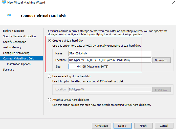
- Select Connect Virtual Hard Disk and set Name, Location, and Size, as shown in the following figure. For details, see the system disk size configuration part in Chapter 2.1 VM Resources.
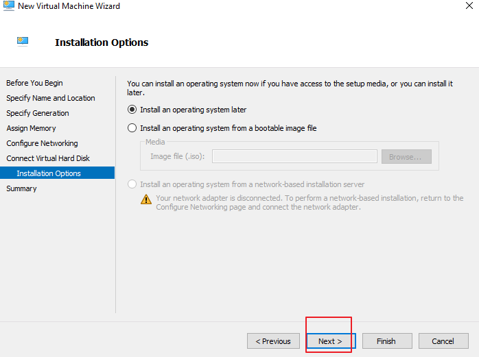
- Click Next. On the Installation Options page, select Install an operating system later and click Next, as shown below.
- Check whether the configurations are correct on the Summary page, as shown below.
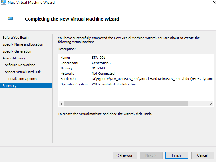
- Click Finish. The VM is successfully created.
VM Configuration
- Right-click the created VM and choose Setting. The configuration page is displayed, as shown below.
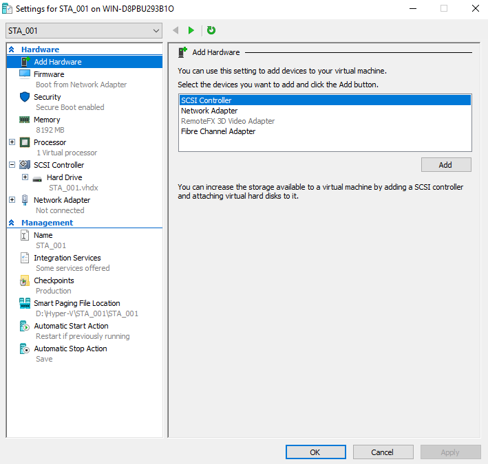
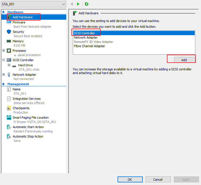
- Add a data disk. Choose Add Hardware > SCSI Controller and click Add, as shown in the following figure.
- The following page is shown.
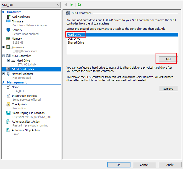
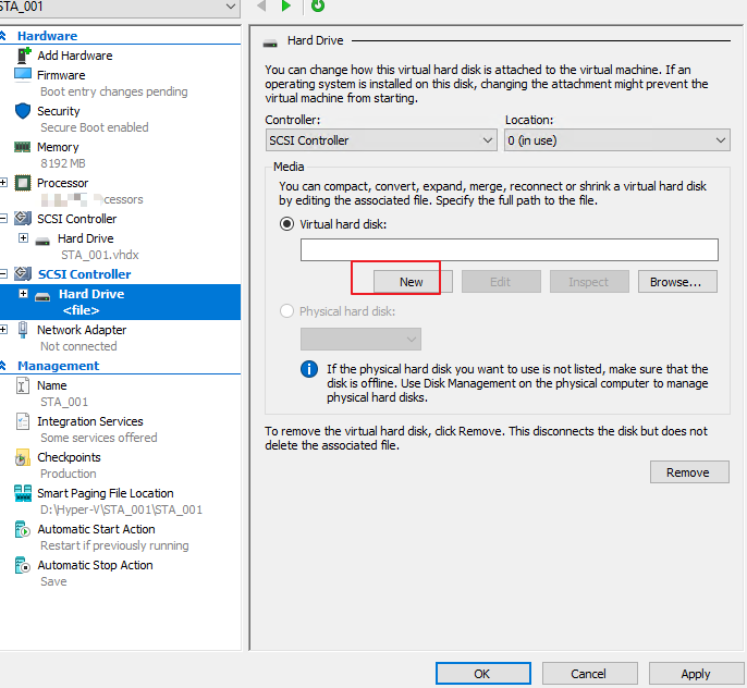
- Click Hard Drive and click Add. On the page that appears, click New, as shown below.
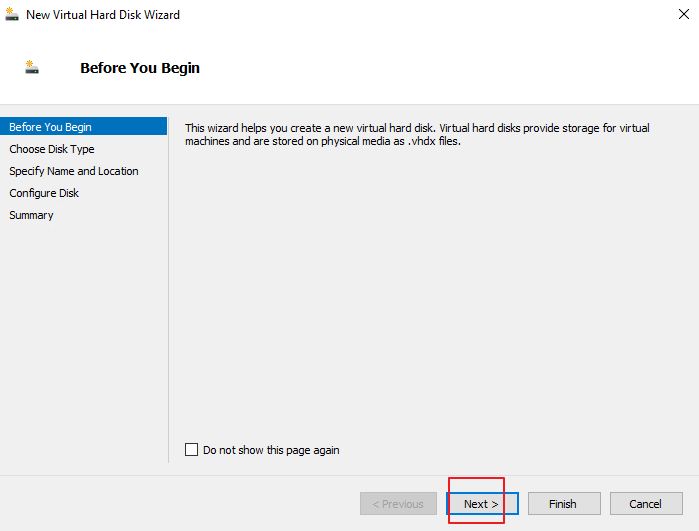
- The New Virtual Hard Disk Wizard page is shown. Click Next.
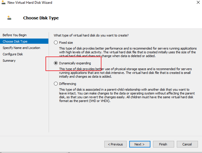
- Click Choose Disk Type on the left and select Dynamically expanding, as shown in the following figure.
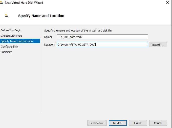
- Click Next. Set Name and Location, as shown in the following figure.
- Click Next. Set the virtual hard disk Size, as shown in the following figure. For details, see the data disk size configuration in Chapter 2.1 VM Resources.
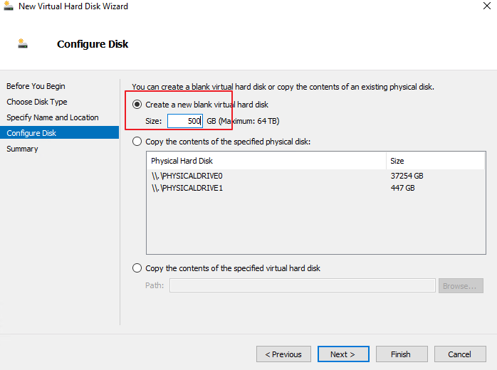
Notice:
The size of a vSTA must be 128 GB or higher.
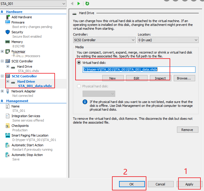
- Click Next and then click Finish. Click Apply and OK in sequence on the configuration page, as shown in the following figure.
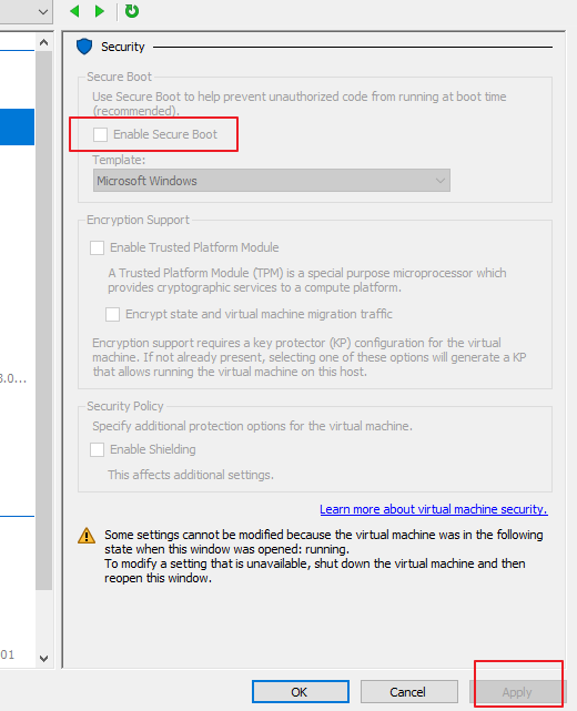
- On the Security page, deselect Enable Secure Boot and click Apply, as shown in the following figure.
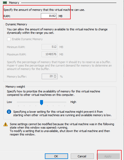
- On the Memory page, check whether the value of RAM is the same as required. If you change the value, click Apply, as shown in the following figure.
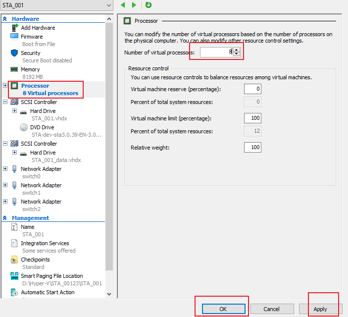
- Change the number of processors. Select Processor on the left. On the page that appears, set the Number of virtual processors to 8 and click Apply and OK, as shown in the following figure. (Using STA with an 8-core CPU and 8 GB of memory as an example.)
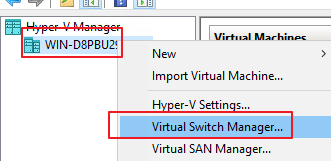
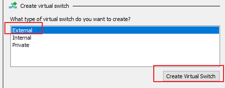
- Configure the network adapter for the Hyper-V server. Then, right-click the server, choose Virtual Switch Manager > External, and click Create Virtual Switch, as shown in the following figures.
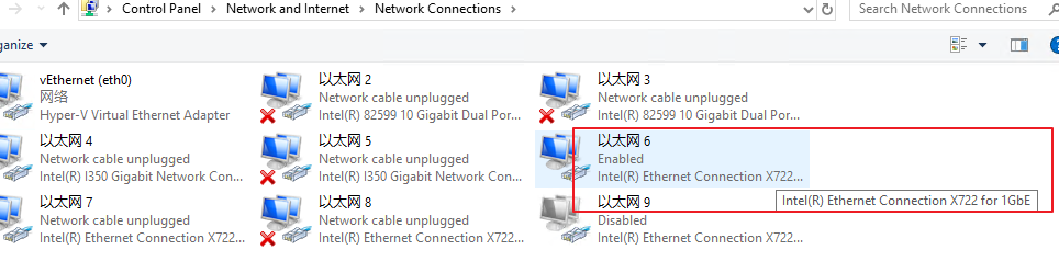
- Go to Control Panel > Network and Internet > Network Connections on this computer and find the network adapter configured with the corresponding IP address. The switch created later will be bridged to this network adapter as the outbound management interface. For example, the IP address configured for Ethernet 6 is used, and the corresponding network adapter name is Intel (R) Ethernet Connection X722 for 1GbE.
- Go back to the VM creation page. First, set Name to switch0 (or any name) and External network to Intel (R) Ethernet Connection X722 for 1GbE. Next, select Allow management operating system to share this network adapter. Lastly, click Apply, and the management interface configuration is complete, as shown in the following figure.
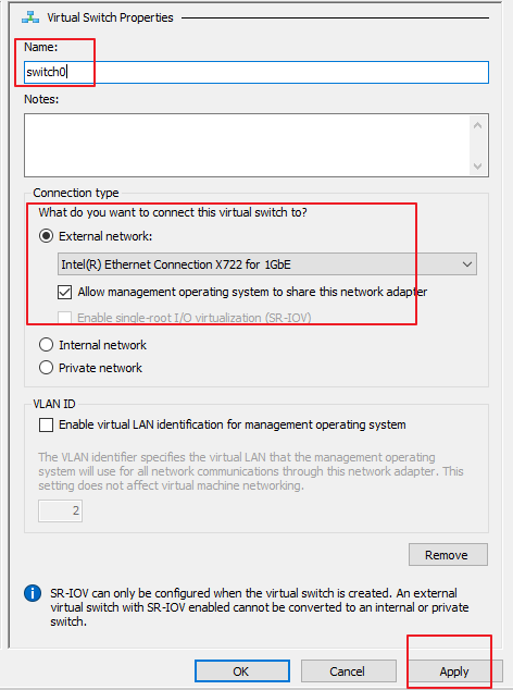
Notice:
The management interface to be added must share the same network adapter with the dependent physical machine in bridge mode. If this option is not selected, the physical machine may fail to connect to the network.
- Add the management interface for the VM.
Right-click the STA VM STA_001, choose Setting > Add Hardware > Network Adapter, and click Add, as shown in the following figure.
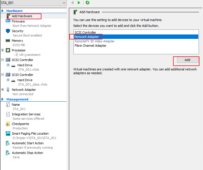
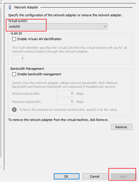
- Select switch0 and click Apply, as shown in the following figure.
- Configure the mirror interface. You can mirror traffic through a virtual switch or SR-IOV passthrough as follows. The STA VM configured in method 1 may have traffic disorder; The STA VM configured in method 2 will have more stable traffic. Therefore, it is recommended to use method 2.
Method 1:
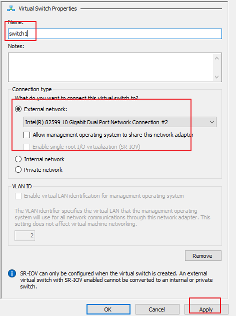
a) Follow step 17 to add switch1 and switch2. Then, select different network adapters as mirror interfaces, deselect Allow management operating system to share this network adapter, and click Apply and OK in sequence, as shown in the following figure.
b) Add the network adapter for the VM.
Right-click the STA VM STA_001, choose Setting > Add Hardware > Network Adapter, and click Add, as shown in the following figure.

Select switch1 and click Apply, as shown in the following figure.
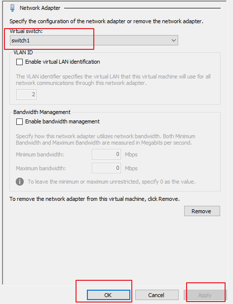
Set the Virtual switch to the network adapter’s name corresponding to the mirror interface, and click Apply and OK in sequence.
In addition, to ensure the STA traffic auditing, perform the following steps:
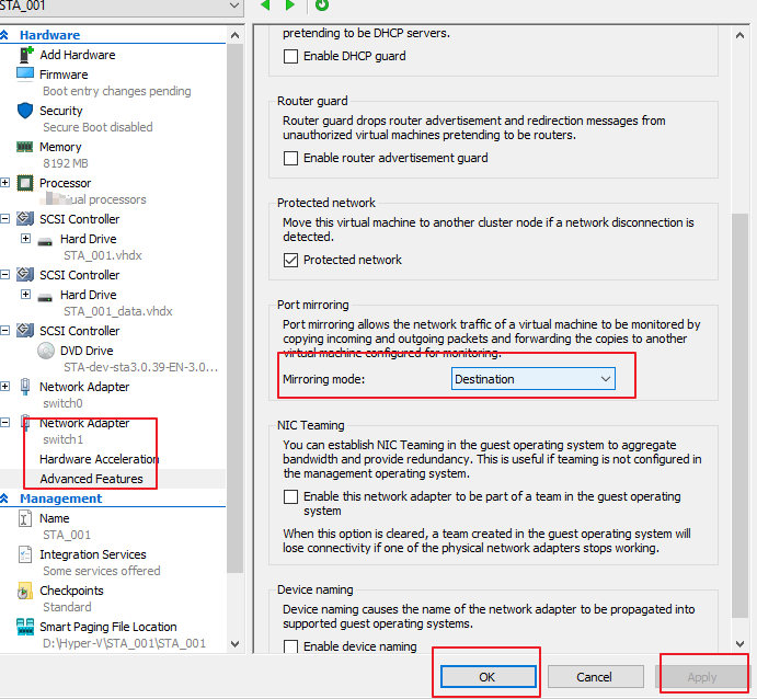
Select the configured mirror interface switch1 and choose Network Adapter > Advanced Features on the left. On the page that appears, set Mirroring mode to Destination and click Apply and OK in sequence, as shown in the following figure.
Open PowerShell on this computer as the admin and run the following commands:
$VMSwitchPortFeature = Get-VMSystemSwitchExtensionPortFeature -FeatureName 'Ethernet Switch Port Security Settings'
$VMSwitchPortFeature.SettingData.MonitorMode = 2
Add-VMSwitchExtensionPortFeature -ExternalPort -SwitchName 'switch1' -VMSwitchExtensionFeature $VMSwitchPortFeature #
As shown below:

Note:
$VMSwitchPortFeature = Get-VMSystemSwitchExtensionPortFeature -FeatureName 'Ethernet Switch Port Security Settings'# Select the extended feature – switch port security settings class.
$VMSwitchPortFeature.SettingData.MonitorMode = 2# MonitorMode parameter description: (0 indicates none; 1 indicates destination; 2 indicates source).
Add-VMSwitchExtensionPortFeature -ExternalPort -SwitchName 'switch1' -VMSwitchExtensionFeature $VMSwitchPortFeature #Add this feature to the virtual switch "switch1", which is the name of the mirror interface set in Virtual Switch Manager. The switch name can set it according to the virtual switch name.
Method 2:
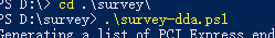
a) Use an official script provided by Microsoft to check whether the network adapter supports SR-IOV passthrough: https://github.com/MicrosoftDocs/Virtualization-Documentation/blob/main/hyperv-samples/benarm-powershell/DDA/survey-dda.ps1
Download survey-dda.ps1 to a local folder, and execute it in PowerShell, as shown below:
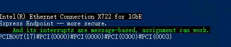
If the green part in the figure below appears, it means the network adapter supports SR-IOV passthrough.
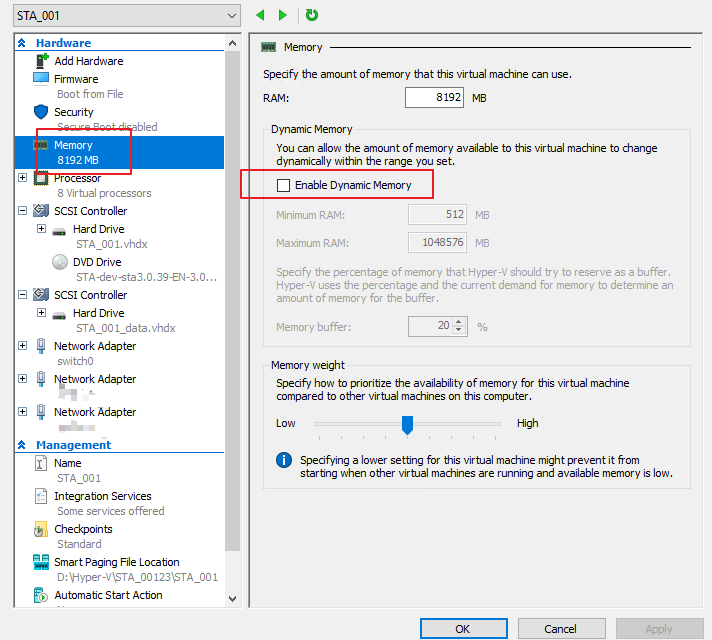
b) Check the Memory settings of the STA VM on hyper-v.
Deselect Enable Dynamic Memory, as shown in the figure below.
On the Automatic Stop Action page, select Turn off the virtual machine and click Apply and OK in sequence to save all the modified settings, as shown in the following figure.

c) Configure network adapter passthrough.
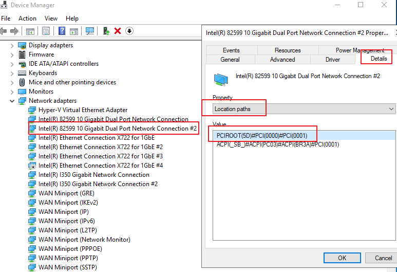
After closing the STA device, right-click the device in Device Manager > Network adapters to enter the Property page, and select Details > Location paths to find the name and location path of the network adapter that needs to enable SR-IOV passthrough. Please configure this based on the actual situation. The network adapter selected here is Intel(R) 82599 10 Gigabit Dual Port Network Connection #2, and the location path is PCIROOT(5D)#PCI(0000)#PCI(0001), as shown below:
d) Execute the following command in Powershell as an administrator to set SR-IOV passthrough. Replace the values of $devname, $locationpath, and $VmName as required.
-
$devname indicates the name of the hardware device that needs to be passed through. In this scenario, it is Intel(R) 82599 10 Gigabit Dual Port Network Connection #2.
-
$locationpath indicates the location path of the hardware device that needs to be passed through. In this scenario , it is PCIROOT(5D)#PCI(0000)#PCI(0001).
-
$VmName indicates the specified VM name. In this scenario, it is STA_001.
-
$devname = ‘Intel(R) 82599 10 Gigabit Dual Port Network Connection #2’
-
$locationpath = ‘PCIROOT(5D)#PCI(0000)#PCI(0001)’
-
$VmName = ‘STA_001’
-
# Disable the device
Disable-PnpDevice -InstanceId (Get-PnpDevice -FriendlyName $devname).InstanceId -
# Uninstall the hardware
Dismount-VMHostAssignableDevice -LocationPath $locationpath -Force -
# The VM cannot be suspended or live migrated, so the automatic shutdown action must be set to ACPI shutdown or hard shutdown.
Set-VM -Name $VmName -AutomaticStopAction TurnOff -
# Assign the device to the specified VM.
Add-VMAssignableDevice -VMName $VmName -LocationPath $locationpath -
# Check the information of the hardware device to be passed through
Get-VMAssignableDevice -VMName $VmName
Note:
If you want to rebind the network adapter to another VM, you need to unbind it from the current VM as follows:
Execute the following command in Powershell as an administrator. Values of $devname, $locationpath, and $VmName need to be replaced as required.#$devname indicates the name of the hardware device that needs to be passed through.
#$locationpath indicates the location path of the hardware device that needs to be passed through.
#$VmName indicates the specified VM name.
$devname = ‘Intel(R) 82599 10 Gigabit Dual Port Network Connection #2’
$locationpath = ‘PCIROOT(5D)#PCI(0000)#PCI(0001)’
$VmName = ‘STA_001’
#Unbind the device from the VM
Remove-VMAssignableDevice -VMName $VmName -LocationPath $locationpath#Mount the device to Windows
Mount-VMHostAssignableDevice -LocationPath $locationpath#Enable the device
Enable-PnpDevice -InstanceId (Get-PnpDevice -FriendlyName $devname).InstanceId
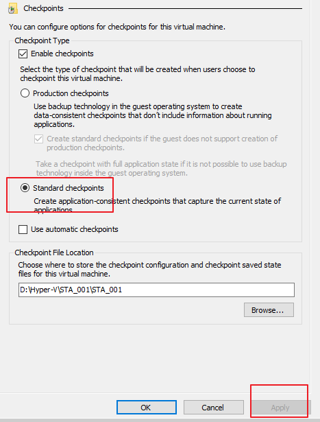
- On the Checkpoints page, select Standard checkpoints and click Apply, as shown in the following figure.
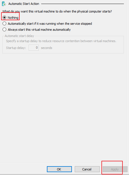
- On the Automatic Start Action page, select Nothing and click Apply, as shown below.
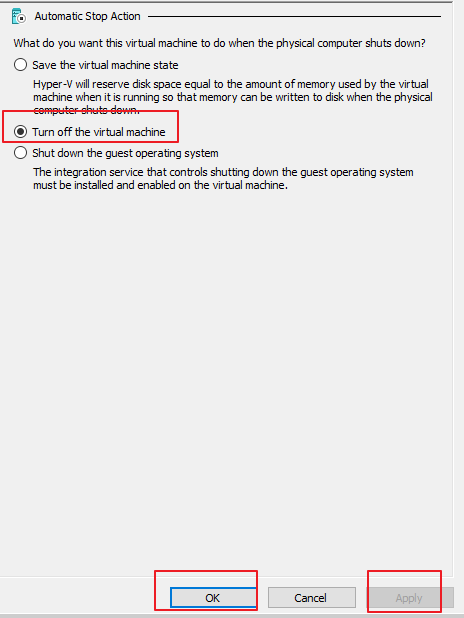
- On the Automatic Stop Action page, select Turn off the virtual machine and click Apply and OK in sequence to save all the modified settings, as shown below.
The VM configuration is complete.
STA Installation
- Prepare the STA ISO file, open the VM configuration page, and select Add Hardware > SCSI Controller on the left. On the page that appears, click Add, then select the Image file under DVD Drive and click Browse, as shown below.
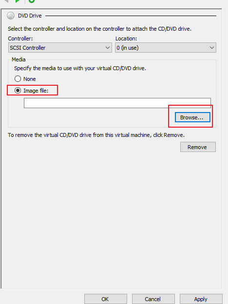
Select the path where the ISO file is located, and click Apply.
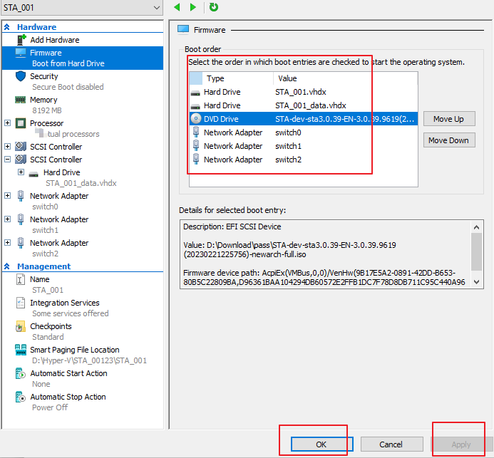
- Adjust the Boot order to the order in the red box in the following figure and click Apply and OK in sequence, as shown in the following figure.
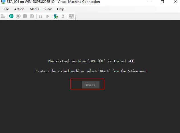
- Right-click the VM STA_001 and click Connect for VM startup and STA installation. Then, click Start, as shown below.
- Select Install SANGFOR STA EN 3.0.39 Automatic.
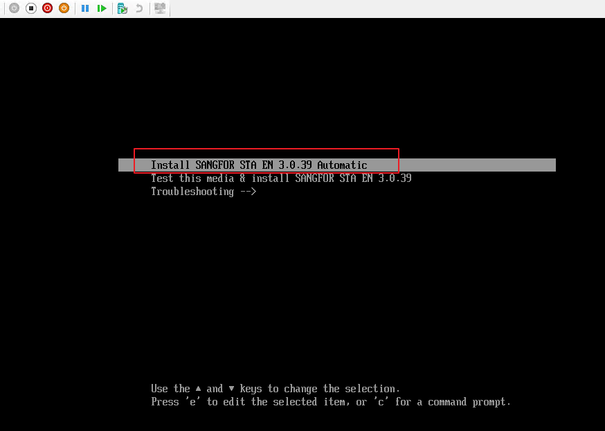
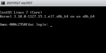
- The system automatically enters the installation phase, requiring no manual operation. First, wait until the window shown in the following figure is displayed. Then, click Reboot to manually restart the VM. After the system restarts, you can view the login status on the console.
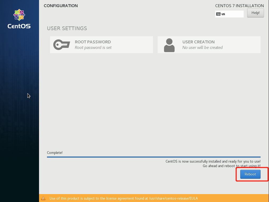
- The installation is complete.
STA Initialization
Network Configuration
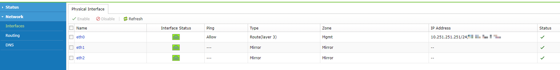
After system installation, the default eth0 interface for vSTA has a pre-configured IP address 10.251.251.251 with a 24-bit mask. You need to find a Windows PC on the cloud platform, connect the network adapter to the same port group and virtual switch, and set the address to an IP address in the network segment 10.251.251.0/24 (which does not conflict with 10.251.251.251). Then, enter https://10.251.251.251 in the browser to access the web console login page. Enter the default username (admin) and password (admin) to log in to the console.
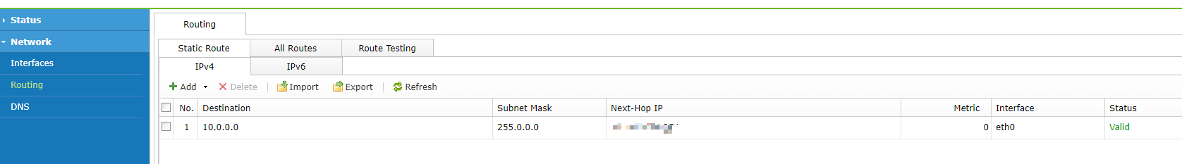
On the web console of vSTA, choose Network > Interfaces/Routing in the left navigation pane. Then, on the Physical Interface/Routing page, set the IP address and route based on the actual situation, as shown in the following figures.
STA Login
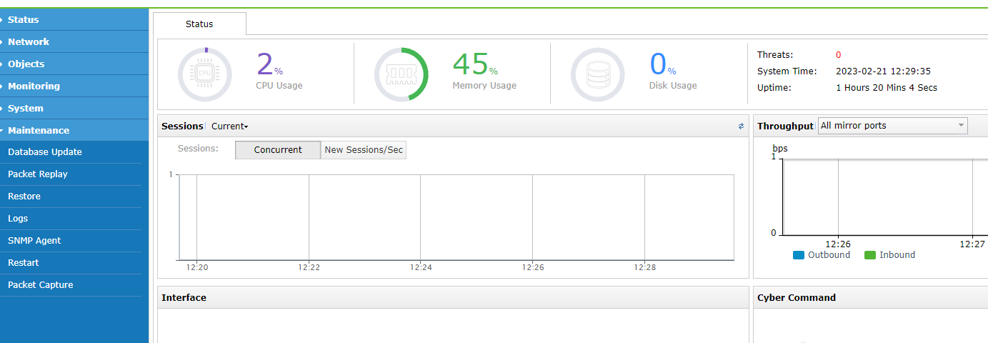
Enter the https://STA management address in the browser of the PC. Then, on the login page that appears, use the default username (admin) and password (admin) to log in to the platform. The following figure shows the page after login.
Note:
If support for IPv6 is required, navigate to System > General > Network in the left navigation pane, click the Network tab, and select Enable IPv4 and IPv6 support. After you click OK, you need to restart the device for the settings to take effect.
Network settings
The following table describes the configuration items of network settings.
| Configuration Item | Description |
|---|---|
| Interfaces | Administrators can choose Network > Physical Interface to add a customized platform management address (next-hop IP address configuration is not required). We recommend using Eth0 as the management interface (which supports IPv4/IPv6). The default static IP address 10.251.251.251/24 cannot be deleted. |
| Routing | 1. Since STA is deployed in bypass mode, only the default route needs to be configured, and IPv6 route configuration is supported. 2. Since network update is not required for STA, no attention needs to be paid to whether DNS is available. |
| Servers | On the Objects > Assets > Advanced page: 1. If administrators can determine the IP addresses of the LAN business system (server) and LAN PC of the customer, configure the LAN server IP group and LAN client IP group. An update is required when the asset scope is extended. 2. If administrators cannot determine the above IP addresses, select Auto-discover servers and services, and leave the Custom internal server IP group and Custom internal client IP group blank. |
| Enable IPv4 and IPv6 support | If IPv6 is available on the customer network, you need to enable IPv4 and IPv6 support on STA. Choose System > General in the left navigation pane and select the Network tab. On the tab, select Enable IPv4 and IPv6 support. |
Table 2: Reference table for network settings
System Time
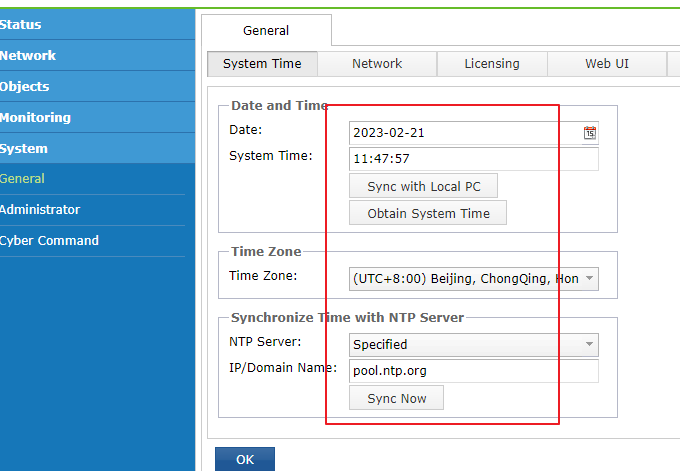
After you log in to vSTA for the first time, check whether the system time is correct. Navigate to System > General > System Time tab. Then, manually adjust the time or use the time synchronized with the NTP server based on the actual situation.
Security Policy Configuration
The following table describes the configuration items of the security policy.
| Configuration Item | Description |
|---|---|
| Detection Policy | It is recommended that all policies be enabled on the Monitoring > Detection Policy page.
Note: |
Table 4: Reference table for security policy configuration
Cyber Command Connection Configuration
The following table describes the configuration items to be set on the System > Cyber Command page of the STA platform.
| Configuration Item | Description |
|---|---|
| Cyber Command | Enter the Cyber Command address and click Test Connectivity to perform the connectivity test and ensure the address is available. |
| Log Types | To ensure the detection effect, select Advanced logs. |
| Protocol Audit | 1. HTTPS audit log: The HTTPS decryption key must be imported to identify HTTPS security issues. To import the Apache private key, click Settings > Add Private Key. |
| Audit File Size | The file size of more than 90% of malicious files is less than 2 MB to facilitate transmission. Therefore, it is recommended to set the Audit File Size to 2 MB on the Advanced page. |
Table 5: Reference table for Cyber Command connection configuration