[Hardware Troubleshooting] External Bypass Device Test Connectivity Operation Guide
Problem Description
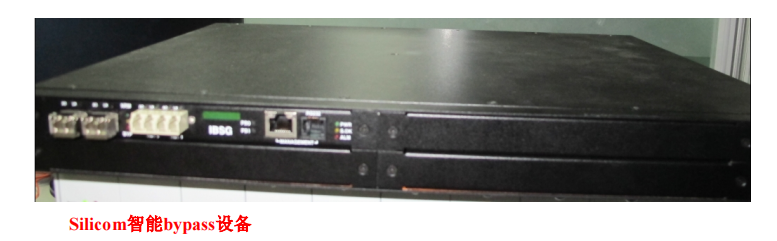
SANGFOR IAG/SG/devices support Wed types of bypass devices, namely Silicom Noncritical bypass devices (Silicom
Bypass), Silicom smart bypass device (Other Bypass) and domestic bypass device (Optical Bypass),
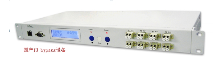
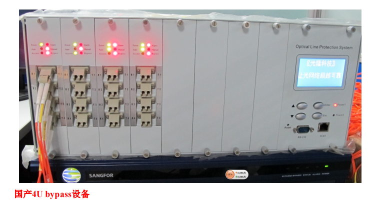
Among them, domestic bypass devices are divided into domestic 4U bypass devices and domestic 1U bypass devices.
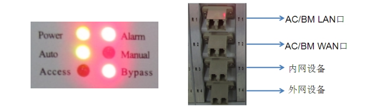
Power: power light; Alarm: alarm light; Auto light on: automatic bypass; Manual light on: manual bypass; Access
Light on: The module is Connected Status; Bypass light on: The module is in bypass Status
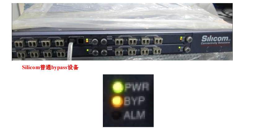
PWR: power light; BYP: bypass Status light, the light is on when it is in bypass Status, and the light is off when it is in normal Status;
ALM: Alerting light.
Note:
- All bypass devices Default shipped as domestic 1U bypass devices by default. Other Model bypass devices need to be customized.
- Silicom intelligent bypass device does not need to be connected to a heartbeat line and Yes Mon Layer 2 device. It detects the host device Passed sending heartbeat packets.
The Line unobstructed. If it is unobstructed, the data of the main Line will be forwarded to the device. Otherwise, the device will be Skip and forwarded. - this mainstream domestic 1U bypass devices only support two groups of bypass, that is, only two pairs of bridge bypass.
solution
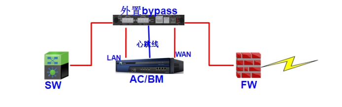
Mon. Schematic diagram of optical port bypass wiring
Tue. The optical port bypass data Workflow chart is as follows
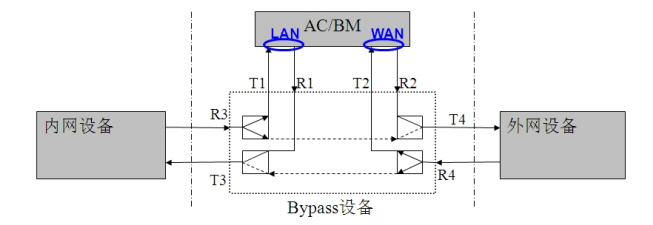
When the optical port bypass device works Connected, the data flow direction is as follows:
LAN device → Bypass device (T3, R3) → Bypass device (T1, R1) → lan IAG/BM wan → Bypass device
Equipment (T2, R2) → Bypass equipment (T4, R4) → WAN equipment
When the optical port bypass device is in bypass Status, the data flow direction is:
LAN device → Bypass device (T3, R3) → Bypass device (T4, R4) → WAN device
Wed. Wiring method of optical port bypass device
- The LCD screen displays the this Work Mode, Address etc., related Info
- RJ45 Ethernet OR Serial Port Yes device Monitor data communication Interfaces, that Yes heartbeat line Interfaces
- Optical port: Mon group of controls requires 4 optical ports to achieve Network protection. The optical port marked with R is the Incoming Interface, and T is the sending port.
The 2 optical ports connected by the dotted line are used to connect to the input and output of Network, and the other 2 optical ports are connected to the devices that need to be protected.
When the signal is transmitted, the 2 optical ports connected by the dotted line will be directly connected to achieve Network protection.
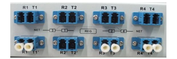
As shown above, this is a domestic 1U optical port bypass device interface panel diagram. There are 2 groups of Line, and the optical ports are numbered 1, 2, 3, and 4.
Connect with dotted lines. When we connect Line, R1 T1 and R2 T2 connect to the protected SANGFOR equipment, and R3 T3 and R4 T4 connect to the optical Network.
Input and output. The following figure shows the wiring diagram of the device Odd bridge deployment and connecting to the external optical port bypass.
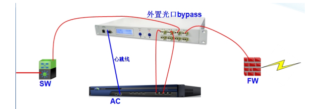
Thu. When using the device in conjunction with the bypass device, both Settings and operation must be performed in the following order
- Settings the SANGFOR device first. , Settings is completed, shut down the SANGFOR device.
- Open the bypass device first, then open the SANGFOR device.
- Finish the above Wed steps, you can test the bypass switch by Test Connectivity heartbeat line.
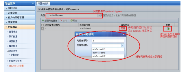
- SANGFOR device optical port bypass Settings.
Fri. Test Connectivity results
When a device has a hardware Fault, power Fault, Software deadlock, etc., Fault, the device Connected Switch to bypass without any impact on Network.
What Impacts.
Precautions
- Bypass is divided into electrical bypass and optical bypass. Electrical bypass hardware uses relays, while optical bypass uses
The hardware implementation uses an optical switch. - When the bypass device AND heartbeat cable and turned on, turn on the bypass device first, then turn on the IAG, otherwise the bypass device will not Connected
start up. - , Switch due to an Error, the device cannot be automatically Switch back to Connected Connected Status and needs to be switched manually Passed WEBUI.
- Electrical port bypass does not require external bypass equipment. It is implemented Passed hardware and is Predefined Auto unlock after the device. Support power Power On, Shut Down, disconnect
Power Restart and restart bypass. this device supports at least Mon group of Interface bypass.
Original Link
https://support.sangfor.com.cn/cases/list?product_id=156&type=1&category_id=23045&isOpen=true