[Hardware Troubleshooting] U.2 Hard Drive Operation Guide
Problem Description
This document Fixed Share to -R dual-socket Services, and is not supported by Odd-socket Services (U.2 Resource belong to the Tue CPU Usage Resource).
solution
Mon. U.2 hard disk installation guide for servers with SN Install with F6H
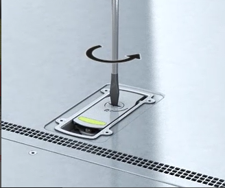
Step One: Remove the top cover, use a screwdriver to tighten the chassis top cover screws, remove the chassis cover, and place it in the designated Region.
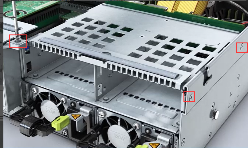
Step Two: Remove the riser 3 components and remove the three screws that come with the chassis one by one, as shown below:
Step Three: Remove the riser3 cable and unplug the cable from riser3 to the motherboard.
Step Four: Delete riser3 module, move it horizontally away from the rear, and then lift it up to take out the riser3 module.
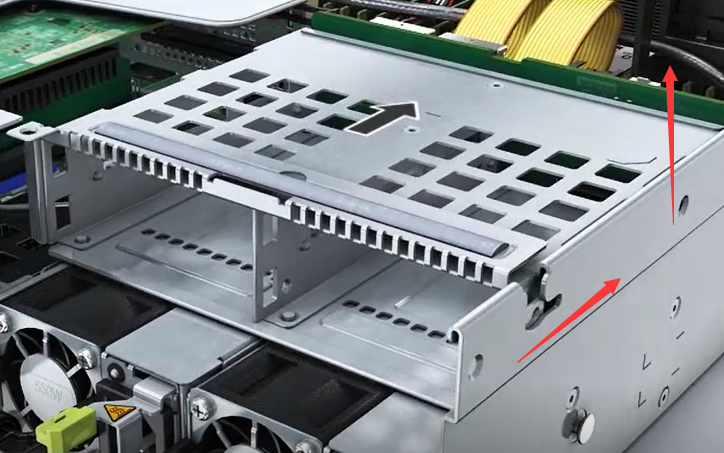
Step Five: Install U.2 module. Install the U.2 module on the chassis in the opposite direction of the riser3 module, and then secure it with 3 screws.
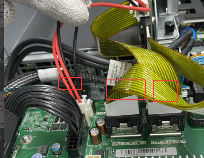
Step Six: Install the cables. Install the four cables shown in the figure below to the motherboard in order. Check that the screws None loose and the hard drive cables None loose. After Install Finish, insert the U.2 hard drive into the hard drive module.
2. U.2 Hard Drive Installation Guide for Servers with SN Install with F6C
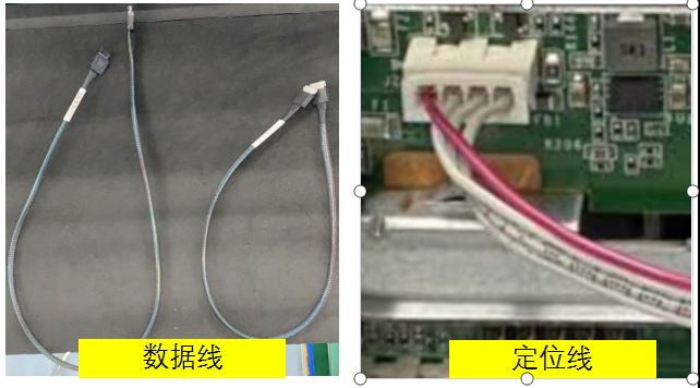
Step One: Check the accessories to be installed, one signal cable and four U,2 data cables.
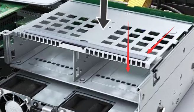
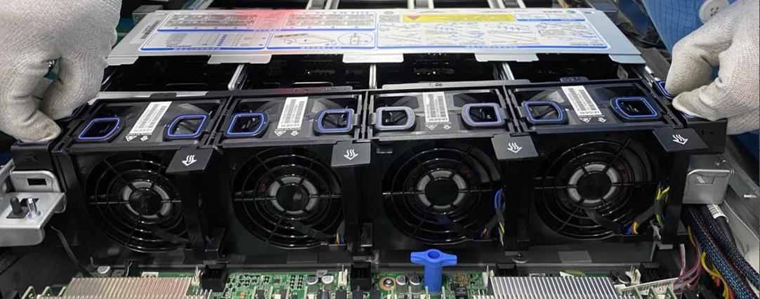
Step Two: Remove the upper cover and the fan module. Hold both ends of the fan module with both hands, take it out horizontally, and then place it in an None but idle Region.
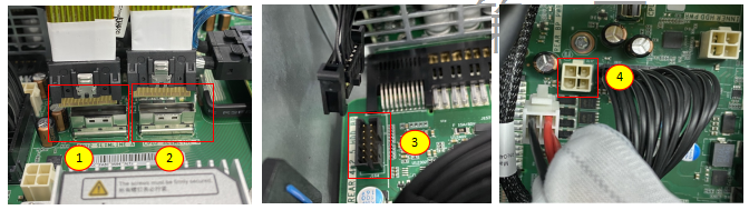
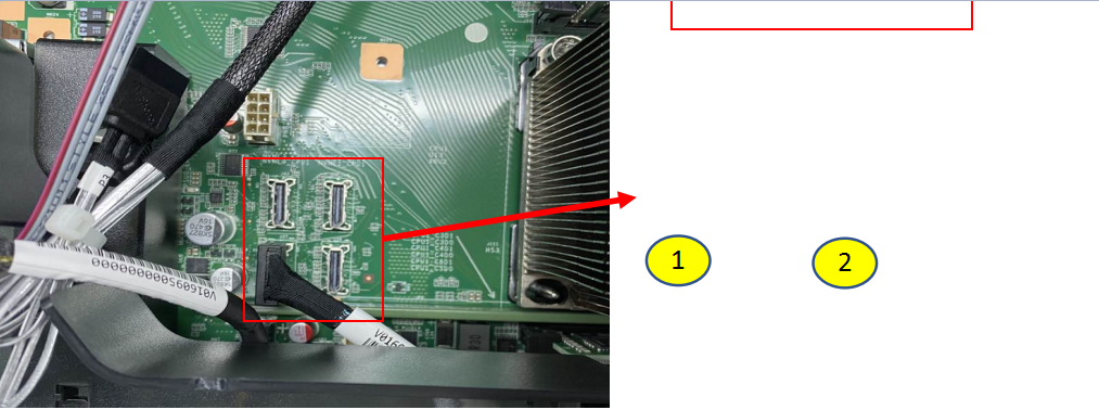
Step 3: Install the cables, find the four NVME interfaces, and connect the data cables Connected NVME0-CPU Usage (①) and NVME1-CPU Usage (②) Interfaces motherboard. Note that the cables have built-in anti-mock Interfaces and cannot be plugged in reverse. Connect the short cable Connected NVME0-CPU Usage and the long cable Connected NVME1-CPU Usage. If there are multiple cables, Install in sequence according to the motherboard (0-1-2-3) slots.
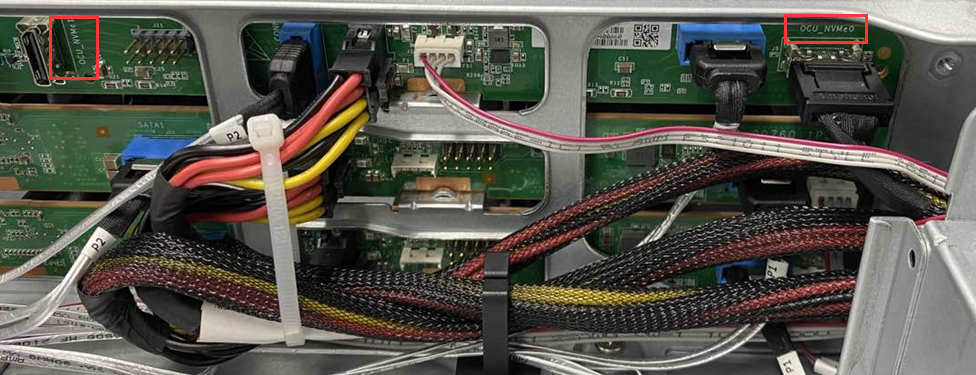
Step Four: Connect the data cables Connected NVME0-CPU Usage (①) and NVME1-CPU Usage (②) Interfaces backplane. Note that the cables have Interfaces anti-mock interfaces and cannot be plugged in reverse. (If there are multiple cables, Install in the order of 0-1-2-3)
Fold the excess portion and snap it into the drawstring.
Notice:
The incoming data cables are two, one long Mon one short. The short cable has a silver-white Interfaces and the long cable has a black Interfaces. Connect the short cable Connected NVME0-CPU Usage and the long cable Connected NVME1-CPU1.
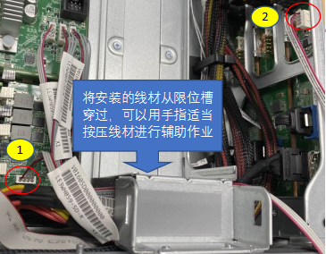
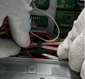
Step Five: Insert Mon end of backplane positioning wire into the interface ① shown in the figure, then pass the wire through the limit slot and insert the other end into the Interfaces ② shown in the figure.
Install, pay attention to the anti-mock Interfaces to avoid reverse insertion.
**Step Six:**After all the cables Install, fold the excess parts and insert them into the straps; install the fan module Install to the chassis Path the original path, then Install air guide cover and top cover, and insert the U.2 disk into the Mon-layer 0-3 characters long..
Wed. U.2 hard disk installation guide for servers with SN Install with F6Q
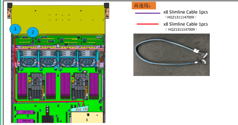
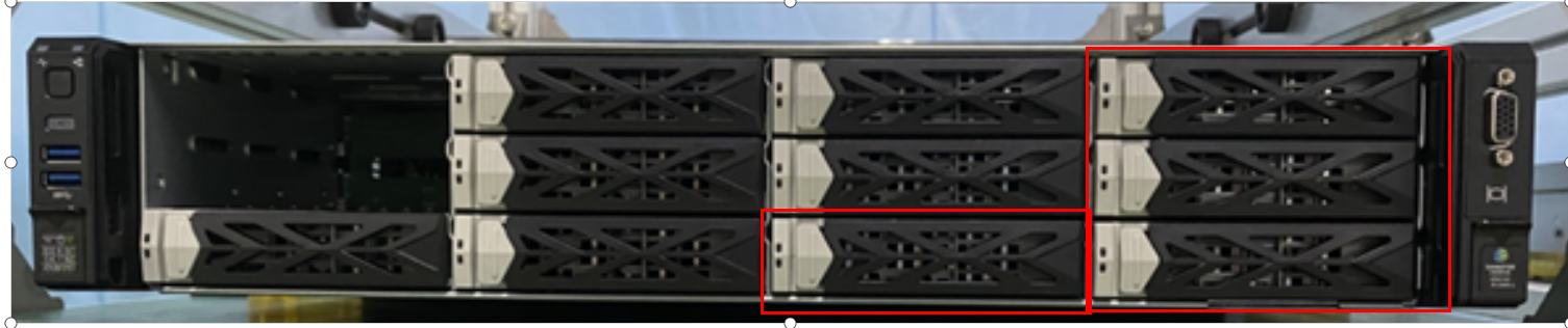
Install 2 high-speed cables at ①-J30 (red cable) and ②-J54 (purple cable). Hard disks are installed at the front 11/10/9/8 characters long.
Thu. U.2 Hard Drive Installation Guide for Servers with SN Install FBC
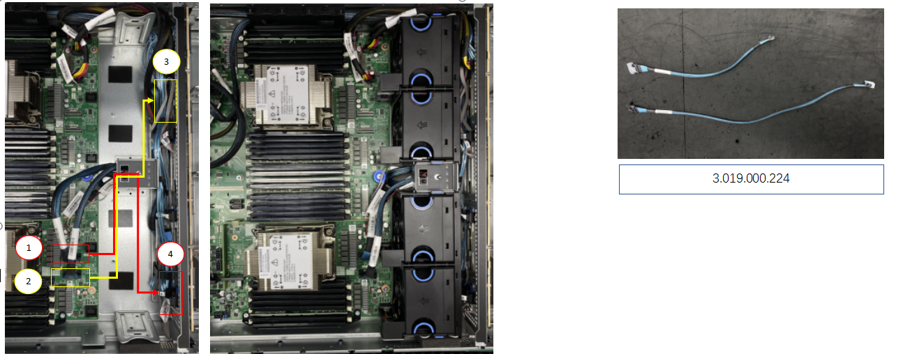
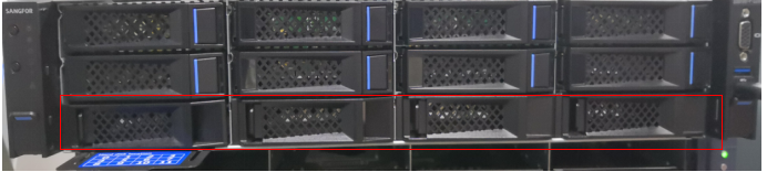
When Install U.2 hard drive, add two high-speed cables, Mon end is installed at the ①-J80 characters long. (short cable), and the other end is installed at the front backplane ④ characters long., as shown in the red line, the Tue cable is installed at the ②-J79 characters long. (long cable), and the Mon end is installed at the front backplane ③ As shown in the yellow line characters long., the hard drive is installed in the front 11/10/9/8 disk characters long..
Original Link
https://support.sangfor.com.cn/cases/list?product_id=156&type=1&category_id=23043&isOpen=true