【HCI】User Manual_V6.8.0
Product Description
HCI (Hyper-Converged Infrastructure) is a product based on innovative hyper-converged technology. It has complete IT infrastructure service capability and operation and maintenance management service capability and can carry core database, ERP, financial system, production system, and other enterprise key business applications.
Unlike the traditional cloud, we are convinced that the hyper-converged is more portable and flexible. It helps users quickly build a business-driven cloud computing data center, pools users’ IT resources, make IT use service, automates its operation and maintenance, and makes key businesses easily put on the cloud. It is the preferred solution for governments and enterprises to put their businesses on the cloud.
This chapter mainly introduces and explains Sangfor HCI products in detail from different aspects, such as product introduction, product architecture, and key features.
Product Introduction
HCI takes resources such as computing, network, and storage as basic components to form a technical architecture that is selected and predefined according to system requirements. The specific implementation method is generally to integrate software virtualization technology (including virtualization of computing, network, storage, and security) into the same set of cell nodes (x86 servers). Each set of cell nodes can be aggregated through the network to realize modular seamless horizontal expansion (scale-out) to build a unified resource pool. We are convinced that the HCI architecture based on HCI can replace the heavy and complex traditional cloud infrastructure and realize the minimalism of cloud architecture.
Relying on HCI technology, HCI simplifies the data center into two kinds of equipment: x86 server and switch, which reduces the initial investment cost and the cost of learning to use the equipment. Smooth capacity expansion is realized by accessing the SCP cloud computing platform to support the demand for high-performance services. HCI has a built-in P2V migration tool, which can realize one-click migration of applications to the cloud and improve its innovation efficiency. HCI ensures data reliability through CDP technology, data multi-copy technology, virtual machine backup technology, application data backup, network behavior management, and other technologies. It has unique optimization technology for key applications, supports the stable operation of key businesses of Oracle RAC cluster, SQL server AlwaysOn cluster, Kingdee, UFIDA, and ERP software, and can meet the needs of the ultra-high reliable business. The built-in firewall, WAF, cloud antivirus, and other business applications running on the cloud platform make them have a perfect security protection system, meet the security and compliance requirements, and effectively prevent East-West security threats in the data center. HCI has global resource management capability. It deploys and configures what you draw is what you get, reduces application deployment time, fault location, and repair time, and can master the use method of the platform without special training.
Product Architecture
Sangfor HCI architecture consists of two parts: HCI and SCP. Based on the HCI architecture, users can build business systems based on their needs.
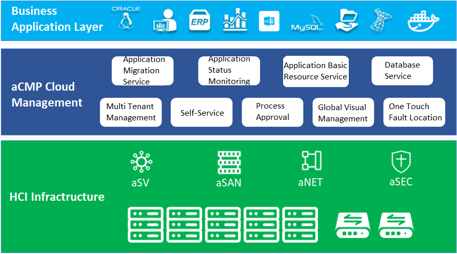
Sangfor HCI is based on HCI architecture, takes virtualization technology as the core, and uses components such as computing virtualization (aSV), storage virtualization (aSAN), network virtualization (aNET), and security virtualization (aSEC) to integrate computing, storage, network, and other virtual resources into a standard x86 server to form a benchmark architecture unit. Moreover, multiple sets of unit devices can be aggregated through the network to realize modular seamless scale-out and form a unified resource pool.
SCP provides the management and resource allocation capabilities of HCI and third-party resource pools. Reduces the difficulty of platform operation and maintenance and reduces the operation workload through automatic operation and maintenance tools. With the help of its self-service and process management, it improves the agility and rapid response ability of users’ IT services to improve its management level and service efficiency. Through the combination of the measurement function of the cloud computing management platform, fine-grained measurement and statistics are carried out on the IT services and resources used by each tenant to help enterprises and organizations calculate the costs and benefits of the Department.
HCI has four main components: aSV (server virtualization), aNET (network virtualization), aSAN (storage virtualization), and aSEC (security virtualization and NFV). aSV is the kernel of the whole HCI and is a required option. aNET, aSAN and aSEC can be selected from three or all according to specific requirements.
aSV is the computing virtualization component in the HCI architecture solution and the core component in the whole HCI architecture. The computing resource virtualization technology presents the standard virtual machine to the end-user through the general x86 server through the aSV component. These virtual machines are like a series of products produced by the same manufacturer. They have a series of hardware configurations and use the same drivers.
aSAN is a self-developed distributed storage system. It uses virtualization technology to "pool" the local hard disk in the general x86 server in the cluster’s virtual datastore to realize the unified integration, management, and scheduling of server storage resources. Finally, it provides the upper layer with NFS / iSCSI storage interface for virtual machines to freely allocate and use the storage space in the resource pool according to their storage requirements.
aNET is a network virtualization component in the HCI architecture solution. It uses Overlay to build the second tier and realize tenant isolation between business systems. Through NFV, all functional network resources (including basic routing switching, security, and application delivery) required in the network can be allocated and flexibly scheduled on demand to realize network virtualization in HCI architecture.
aSEC is a trusted security virtualization and NFV (including: vAC, vAD, vAF, vSSL VPN, vWOC, VDAS). It will be convinced that the existing network devices (SSL, WOC, ad, AF, AC, DAS) will be virtualized and provided separately in the form of templates.
Key Characteristics
Key Features of SCP
-
SCP
Sangfor SCP can provide rich management functions, including hosting HCI clusters and VMware vCenter, supporting unified licensing for multiple HCI clusters, and supporting multi-tenant management and independent service management. In terms of security, support tenants to configure their own distributed firewall policies. In terms of disaster recovery, SCP integrates the reliability center, which can provide users with a complete remote disaster recovery scheme at the virtual machine level.
-
Application Migration Service
HCI migration tool can copy the existing physical node or windows / Linux operating system on VMware or Citrix platform to the HCI platform through the network.
-
Heterogeneous Virtualization Management(aHM)
HCI can add VMware vCenter and manage it to realize centralized management of dual platforms. Virtual machines between VMware vCenter and HCI can support two-way migration.
-
Database Wizard Deployment
Oracle RAC on the HCI platform supports wizard deployment and SQL Server AlwaysOn cluster database.
-
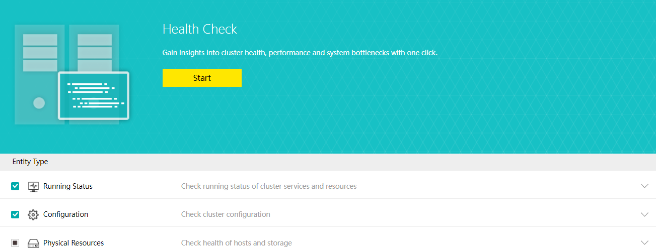
Health Check
Health Check can identify the system hardware, configuration, and system operation, quickly locate the problem location (hardware, platform, and business), conduct the layered inspection, and provide detailed fault solutions.
-
Resource Scheduling
Resource scheduling refers to scheduling cluster resources in specific scenarios, migrating virtual machines from nodes with high CPU or memory usage to nodes with low utilization, and reducing the utilization of nodes with an excessive load below the threshold.
-
Virtual Machine data Protection
- Virtual machine snapshots are similar to system restore points. A virtual machine can have multiple snapshots.
- The virtual machine backup mode supports full backup and incremental backup of virtual machines. The first virtual machine backup of the user is the full backup of the virtual machine, and other backups within the backup retention period are incremental backups.
- CDP is continuous data protection. It can record every IO of the business system to the disk in the virtual machine, restore the virtual machine to the state at any time, or directly view and download the file at a particular time. It is of great value for file deletion, viruses, system crashes, data damage, and other faults, so the RPO is close to 0.
- Power On Expansion
It supports the expansion of existing disks when the virtual machine is powered on to avoid downtime caused by the expansion of virtual machine disks.
- Bulk Clone Migration
- Support batch cloning of virtual machines.
- Support batch migration within the cluster.
- Support batch migration across clusters.
- Single Node Maintenance
The maintenance mode can be set for a single node. For a node that enters the maintenance mode, tasks will not be scheduled to the node for execution to reduce the impact on business during physical node maintenance.
- Security Policy For Classified Users
- Syslog log reporting is supported.
- Ukey dual-factor login is supported.
- Support IP + Mac and terminal binding policies.
- System Disk Replacement
-
Support health inspection and lifetime prediction of existing system disks.
-
Support scheduled backup of system configuration and user configuration of the system disk.
-
Support the safe replacement of the node’s system disk.
aSV key Features
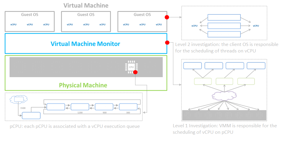
- Hypervisor Implementation of aSV
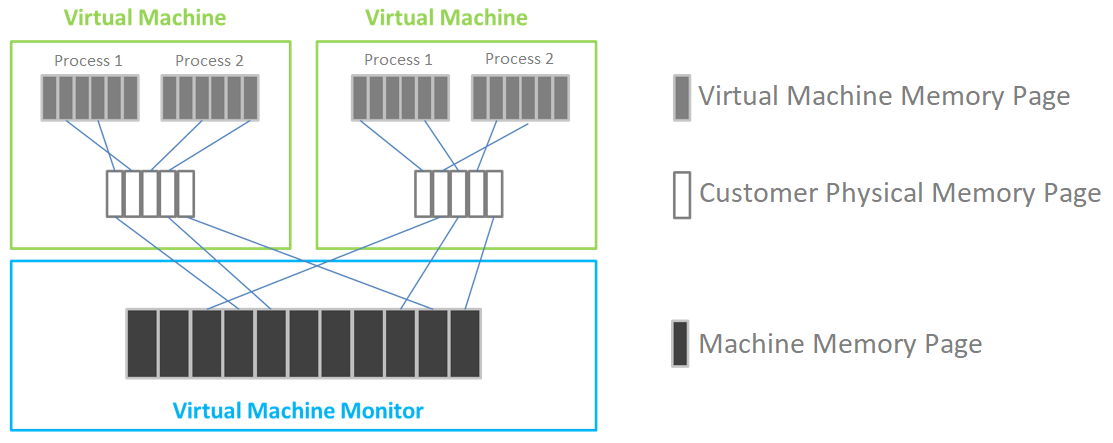
The aSV platform virtualizes CPU, memory, and IO devices through VMM (Virtual Machine Monitor).
Based on hardware-assisted virtualization technology, aSV uses VMM to realize the virtualization of x86 architecture and divides a single physical CPU into multiple vCPU. The virtual machine only sees the vCPU presented by VMM and does not directly perceive the physical CPU. The user operating system is responsible for the level 2 schedule, the scheduling of threads or processes on vCPU. The virtual machine monitor is responsible for the level 1 schedule and the scheduling of vCPU on the physical processing unit.
aSV completes memory virtualization based on page table virtualization technology. VMM is responsible for page memory management, maintaining the mapping relationship from virtual address to machine address, virtualizing physical memory into the virtual machine, and using virtual memory.
aSV uses VMM to intercept the access request of Guest OS to I/O devices and then simulates the real hardware through software to realize I/O virtualization.
- Virtual Machine Resource Hot Add
aSV supports hot addition to the CPU and memory of the virtual machine and hot plug to the interface and disk of the virtual machine.
- Dynamic Thermal Addition
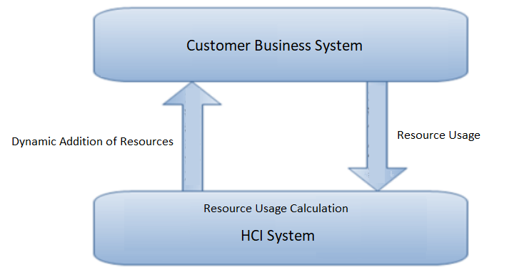
The automation strategy provided by the automated hot addition function can quickly respond to the growth and change of the business state. Dynamically expand the virtual machine’s CPU and memory resources, ensuring business continuity and solving the agile operation and maintenance problems caused by user business growth.
- Virtual Machine High Availability (HA)
Virtual machine high availability (HA) is divided into node failure HA and virtual machine failure HA.
- Node failure HA means that when the node where the virtual machine is located has an accident (node power outage, interface drop, etc.), a node with sufficient resources will be selected to restart the virtual machine, which significantly reduces the service interruption time.
- Virtual machine failure HA refers to shutting down the virtual machine and restarting it on the original physical node when the virtual machine has a blue screen, black screen, and other failures.
- Virtual Machine Rapid Recovery
The rapid recovery function can immediately create and start the virtual machine when it needs to be restored. The process can be completed in 3 minutes, and the performance will climb to the normal within 15 minutes, which can quickly help users restore business operation and ensure business continuity. RTO <= 15 minutes.
- Intelligent NUMA Scheduling
By modeling the core business database and using an AI algorithm, the NUMA binding rule base of the core database in the general scenario is generated to improve the business performance.
- Memory Isolation, Memory Over Allocation, and CPU Over Allocation Limits
By isolating the memory area of each module, the system will not be suspended or shut down due to memory preemption to improve the platform’s reliability. At the same time, it supports the over allocation of virtual machine CPU and memory, and the actual usage can exceed the physical limit. Give priority to ensuring the memory usage of important virtual machines and improving the CPU and memory usage.
- Sub health node monitoring
Monitor whether the system disk and memory of the node in the cluster are in the sub-health state, give treatment opinions to the sub-health node and reduce the priority of the sub-health node in the process of virtual machine startup (or HA) node selection. Currently, it supports processing five sub-health states: memory CE and UE errors on the node, read-only system disk, insufficient SSD lifetime, and bad channel on HDD.
aSAN key Features
- Data Striping
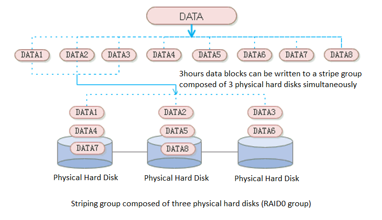
aSAN uses striping technology to maximize I/O concurrency. Striping technology is to cut a piece of continuous data into many small data blocks and then stores them concurrently on different physical hard disks to achieve the maximum I/O concurrency when writing or reading data to obtain excellent performance.
As shown in the figure below, striped data can be written to three disks concurrently, while non-striped data can only be written to one disk at a time. Therefore, the write performance of striped data is three times that of non-striped data.
- Zone
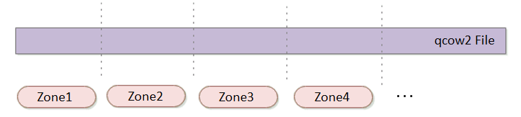
aSAN divides a single qcow2 file into several smaller pieces according to a fixed unit size through data fragmentation technology. Make data more evenly distributed in virtual datastores and data management more flexible.
- Multi Replica Mechanism: Supports 2 Replica and 3 Replica
It also supports 2 replica and 3 replica policies. For virtual machines carrying important business systems, users can choose to configure three replica policies to further improve the reliability of data. Support the conversion between 2 replica virtual machines and three replica virtual machines to achieve the best balance between high reliability and high performance.
Common storage strategies are built in the platform. Users can select corresponding storage policies when creating virtual machines according to the characteristics of business systems. At the same time, users can configure more detailed storage policies with the virtual machines as granularity according to the characteristics of the business system, which makes the configuration more flexible. Contains the following four attributes:
-
Replicas: Reliability index, two or three replicas can be selected according to the importance of the business.
-
Automated QoS: Performance indicators, including high performance, default performance, and low performance.
-
Strips WIdth: Performance index, the system will automatically set the number of strips or customize them according to the current storage state of the hard disk.
-
Replica Defrag: Performance indicator to ensure IO localization and improve read performance. An aggregate replica is enabled by default.
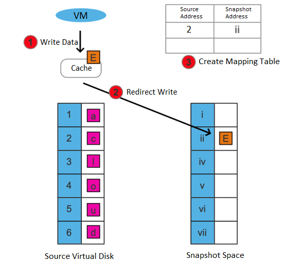
- Storage Snapshot
Supports the storage snapshot function. When creating a virtual machine snapshot, the system will set the source virtual disk as read-only and generate a corresponding number of new disk files (i.e., snapshot space).
After the snapshot is created, all new data and modifications to the source data of the virtual machine will be written to the newly generated snapshot space. The corresponding relationship between the logical address of the source virtual disk and the snapshot space will be written in the mapping table.
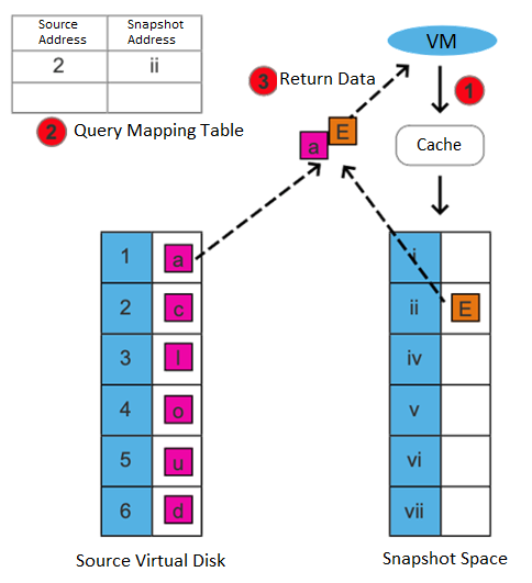
After the snapshot is created, there are two situations for the virtual machine to read data:
-
If the data read is the existing data before the snapshot is created and has not been modified after it is created, it is read from the source virtual disk.
-
If the read data is newly added/modified after the snapshot is created, it is read from the snapshot space.
This snapshot method has the following advantages:
- Redirect on write (ROW) is used to realize the snapshot, and the virtual machine’s performance will not be affected after the snapshot.
- After deleting a snapshot, you can free up storage space (initiate the snapshot residual file cleanup task).
Support consistency group snapshots to ensure the consistency of Oracle RAC and distributed services:
- Support adding virtual machines in Oracle RAC or multiple virtual machines hosting the same business system as consistency groups. Take snapshots for consistency groups to ensure that all virtual machines in the group take snapshots simultaneously.
- When the virtual machine in the consistency group fails, the virtual machine in the group can be rolled back to a consistent state by using the consistency group snapshot.
Support scheduled snapshots, simplify operation and maintenance, and make data more reliable:
- Support custom scheduled snapshot policies for individual virtual machines and consistency groups.
- The snapshot frequency can be selected by hour, day, and week. At the same time, to avoid frequent snapshots occupying a lot of storage resources, you can set the snapshot automatic cleaning policy. The system will automatically merge snapshot points and effectively use storage space.
- In the development test scenario, scheduled snapshots can greatly simplify operation and maintenance and improve data reliability.
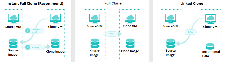
- Virtual Machine Cloning
On the basis of full cloning of virtual machines, it supports both link cloning and fast full cloning of virtual machines.
The virtual machine generated by the linked-clone always depends on the source image to start and run. When the data is added or changed, it will be recorded and redirected to the new image. It has the characteristics of fast virtual machine startup, non-independent data, saving storage space, and performance will still be affected after cloning.
The virtual machine-generated by fast full cloning depends on the source image in the early stage and can be started in seconds. After the virtual machine start, the data will continue to be cloned, and the final data will be complete and independent. It has the characteristics of a fast virtual machine startup, final independent data, and no impact on the performance after cloning.
The virtual machine clone type can be flexibly selected, and the fast full clone type is recommended by default.
- Host Multi Volume
HCI supports the establishment of multiple storage subvolumes by selecting different nodes in a cluster. It meets the user’s requirements for different services’ capacity and performance isolation. Also, it enables the business to switch between different storage subvolumes to realize the different performance requirements of the same business at different stages.
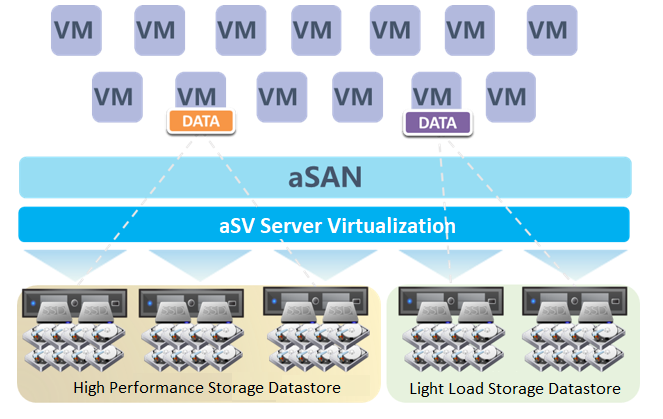
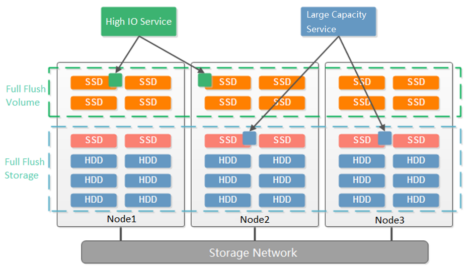
- Disk Multi Volume
Dividing multiple volumes by host can only be supported when at least 6 hosts start. Small clusters with small business nodes cannot be divided into multiple volumes by node. However, multiple volumes can be divided by the hard disk.
As shown in the figure below, starting from three nodes, aSAN supports dividing into two volumes according to the granularity of the hard disk. Compared with dividing virtual datastore according to nodes, it reduces the deployment threshold of multiple volumes. When customers have two types of services: high-performance and high-capacity, they can be divided into two volumes according to the hard disk: one flash volume + one hybrid volume. The flash volume runs high-performance services, and the hybrid volume runs high-capacity services.
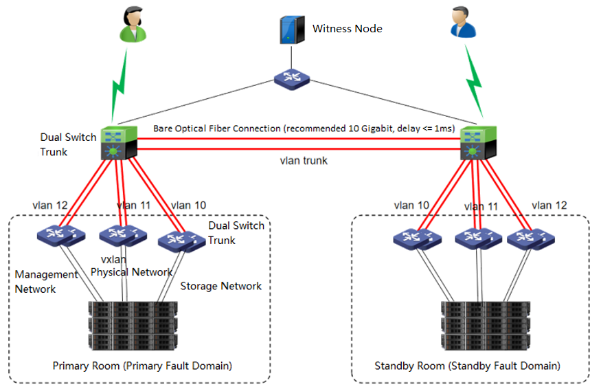
- Extended Volume
The dual-active data center is realized through the scheme of extending the cluster. The witness node must be deployed in this scheme to solve the split-brain problem and ensure data reliability. On average, the HCI node forms a cluster and is deployed to two machine rooms. Each machine room is configured as a fault domain, and each fault domain saves a copy. The data will be written to two copies simultaneously, and if any machine room fails, Data will not be lost.
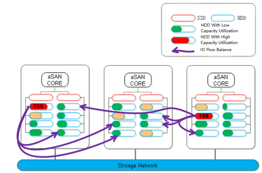
- Data Balance
During distributed storage, the disks between nodes may also be used unevenly. When it is found that the difference between the highest and lowest disk capacity utilization in the volume exceeds a certain threshold, aSAN will calculate the location of each partition on the source side disk and the destination side disk it is about to fall into. The number of destination disks can be multiple; the location can be other disks in the node or disks in other nodes.
- Data Rebuilding
Through the data rebuilding function, after a component (disk or node) fails, aSAN will take another copy of the data on the failed component as the repair source, rebuild a new copy on the target component in the unit of fragmentation, restore the integrity, and realize system self-healing.
- Virtual iSCSI Technology
aSAN has virtual iSCSI technology. It can create a virtual iSCSI hard disk and supports access from a virtual storage network interface.
- Heterogeneous storage management
-
HCI supports adding FC storage and iSCSI storage as external storage, placing the datastore of virtual machines on FC storage or iSCSI storage, and realizing the HA function of virtual machines.
-
HCI supports adding NFS as the backup location of virtual machines.
-
HCI supports adding local or on-server disks other than the server system disk. After the RAID is formed, the logical disk is used as the virtual machine’s datastore, but the virtual machine’s HA function is not supported.
- Disk Sub-health Scanning And Repair
-
aSAN can find hidden bad sectors in time through the active scanning function of bad sectors to avoid the data being in the single-copy state for a long time.
-
When aSAN finds a bad sector, it will immediately trigger the repair of the bad sector data, read the data from another copy, repair it to the reserved sector of the bad sector disk, and recover the redundancy of the data copy in time.
-
aSAN actively migrates all data on hard disks with too many bad sectors (or SSD lifetime is about to run out) to other healthy hard disks in advance and always maintains the redundancy of replicas.
-
When the hard disk gets stuck, slows down, is congested, and under other abnormal conditions, it will affect the performance. At this time, the continuity of performance is guaranteed through sub-health disk isolation and read-write source switching.
- Bad Sector Prediction
We independently developed a high-precision bad sector prediction function by collecting and analyzing the SMART data, performance parameters, and hard disk log information of bad sector hard disks in many customers’ actual scenarios, combined with advanced algorithm training models. The accuracy of aSAN’s bad sector prediction is 95% above through many different business scenario tests.
- Capacity Prediction
aSAN can dynamically predict the capacity growth trend in the next 90 days according to the capacity usage of customer clusters. In the capacity prediction interface, the user can switch and view the raw capacity, actual used capacity, and dynamic prediction curve of different virtual datastore. It will prompt the user that the used capacity will reach the capacity alert threshold (90%) in XX days.
- SSD Lifetime Prediction
aSAN collects and analyzes the IO data of SSD hard disks in the cluster, calculates the remaining lifetime of SSD hard disks, and displays the expected remaining available time of SSD in combination with the upper business pressure. According to the prediction results, it is divided into three-lifetime levels: Healthy, Medium Risk, and High Risk. Notify users to replace the SSD hard disks in the cluster in time.
aNET Key Features
- Network Virtualization
-
The virtual distributed switch can ensure the consistency of network configuration when virtual machines migrate between nodes. It provides rich network configuration management functions, dynamic interface binding, and static binding.
-
The distributed firewall provides IP access control and virtual machine network QoS to realize unified management of network resources and real-time network monitoring.
-
The virtualization router can solve the problem of exit routing after virtualization and provide other functions, including VLAN subinterface, NAT rules, ACL policy, DHCP address pool, DNS proxy, and so on.
- Virtualization of Network Functions
Network Function Virtualization (NFV) separates network functions from proprietary hardware devices and implements these functions as software to support the infrastructure with complete integration of virtualization components. Sangfor’s HCI platform is complete in implementing NFV, including Sangfor network equipment software with leading technology in the security field, including vAF, vAD, vAC, vWOC, vSSLVPN, etc.
- Distributed Virtual Firewall
A distributed firewall is equivalent to placing a firewall at the exit and entrance of each virtual machine. As long as a policy is configured, it can dynamically adjust in the background no matter how the topology changes, where the virtual machine runs, or change of the IP. Therefore, security protection can be carried out at any time.
Installation And Deployment
Networking Installation Introduction
Precautions
| Node interface | Recommended minimum 6 Ge + 2 10GE | Prohibit the use of networks below Gigabit. | |
|---|---|---|---|
| Networking deployment | Storage private network | It is recommended to make dual switch link aggregation and adopt a 2 * 10GE interface. | 1. Must use the 10 Gigabit interface to build the storage private network. 2. Linkless aggregation is prohibited. |
| Networking deployment | Management network | It is recommended to stack and deploy, use 2 * Ge interfaces for aggregation, and use the IP address for a load. The corresponding interface of the switch needs to be configured with static interface aggregation. The networking switch of the cluster management interface and Overlay Network Interface needs to support multicast function. Otherwise, the cluster cannot be established. | IGMP snooping is prohibited. |
| Networking deployment | Service network | It is recommended to stack and deploy, use 2 * Ge interfaces for aggregation, and use the IP address for a load. Static interface aggregation needs to be configured for the corresponding interface of the switch. | – |
| Networking deployment | VXLAN network | It is recommended that the 2 * Ge network interface be aggregated, loaded in the IP address mode, and turned on the high-performance mode. The connected switch needs to turn on the jumbo frame, which is set to more than 1600 (the Xinrui switch is set to 2000). At the same time, the corresponding interface of the switch needs to be configured with static network interface aggregation. (it is allowed to reuse the VXLAN and service network when the equipment network interface is insufficient). | 1. A high-performance mode must be enabled for the VXLAN network settings of the HCI platform. 2. IGMP snooping is prohibited. |
| Networking deployment | Switch | The STP function must be turned off at the networking port on the switch. Except for the storage switch, other switches adopt stacked deployment. | Single switch deployment without redundancy is prohibited. |
| Networking deployment | IP address planning | It is recommended that the management network segment, VXLAN network segment, and service network segment be divided into different network segments to avoid IP address conflict. | – |
| Networking deployment | Network cable specification | 1. It is recommended to use multimode optical fiber within 50m and single-mode optical fiber over 50m. 2. It is recommended to use category 5 and above twisted pair. |
1. It is forbidden to connect a single-mode optical fiber to the multi-mode module. 2. It is forbidden to connect a multimode optical fiber to the single-mode module. 3. Class 1 to 4 twisted pair is prohibited. |
| Networking deployment | Dual active networking | 1. The bandwidth between the witness node and the active and secondary fault domain is recommended to be more than 100Mbps, and the delay is < = 1ms (fluctuation within 5ms is allowed). 2. The primary fault domain and the secondary fault domain of the stretched cluster volume must be connected with 10 Gigabit bare optical fiber, with a delay of < = 1ms. |
– |
- The networking switch of the Overlay Network Interface shall confirm whether it supports the jumbo frame. If yes, it is recommended to turn on the high-performance mode of the Overlay Network Interface and change the MTU of the VXLAN port to 1600. If it is not supported, it is forbidden to turn on the high-performance mode of the Overlay Network Interface. Otherwise, the data of the virtual machine will be blocked.
- The connectivity detection of Health Check is only Ping detection. Even if multicast fails, the detection result is normal as long as Ping is enabled.
- The four communication interface types (management communication port, VXLAN Overlay Network Interface, VS Storage interface, and physical interface) are not allowed to be multiplexed. However, in the case of an insufficient network interface, and you have to reuse the network interface, please reuse the physical interface and VXLAN interface. It is suggested that the network interface should be planned as two management interfaces, two storage interfaces, and two aggregation interfaces for VXLAN and physical export reuse.
- Do not hot-plug the NIC, whether a third-party server or an HCI aServer. Otherwise, the network interface may be out of order.
Introduction to HCI Ordinary Cluster Networking
HCI standard networking topology is as follows.
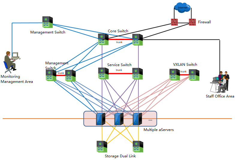
Explanation of terms:
-
The management network to reuse the management network for platform management, server IPMI, BMC, IDRAC, and other remote management network interfaces.
-
VXLAN network carries the east-west traffic of virtual machines and layer-2 communication.
-
A storage network is for aSAN storage, responsible for storage data communication between HCI nodes; When using IPSAN, it also serves as an interface for communication with external storage, layer-2 communication.
-
The service network carries the North-South communication of virtual machines.
Networking Description:
- Core layer
Using the data center core switch with high-capacity network message forwarding capability is recommended. The switch model is required to support stacking or clustering technology, and the downlink port rate is 10GE.
- Access layer
In the large-scale deployment scenario, it is recommended that the management, service, and VXLAN network planes adopt two stacking technology-supported switches(Gigabyte) data centers. The GE rate downlink connects to the server, and the uplink port rate is 10GE. Multiple 10GE links access the core switch using link aggregation to build a redundant, low convergence ratio and non-blocking service switching network. The storage network adopts two independent 10 Gigabit switches to do link aggregation with two switches to ensure Virtual Storage performance and improve the robustness of the whole network architecture. During deployment, the two hosts are aggregated and directly connected, and dual switch link aggregation should be selected.
In the small-scale deployment scenario, two stacked data center switches(Gigabyte) are recommended in the management, service, and VXLAN network planes. Each network plane is divided into different VLANs for logical reasons of isolation. The storage network also adopts two independent 10 Gigabit switches and dual switch links to ensure Virtual Storage performance and improve the robustness of the whole network architecture.
When the server is configured with 6 GE and 2 10GE network ports, the management, business and VXLAN networks adopt 2 GE network ports respectively, and the network ports are aggregated and bound; The storage network adopts 2 10GE network port and dual switch link to increase network redundancy and transmission bandwidth
For the management, service, and VXLAN network planes, the server network card aggregation supports three load balancing modes: IP, MAC address, and polling. It is recommended to use the IP mode for load balancing. The access layer switch interface needs to be configured with the corresponding interface aggregation mode. If the incoming switch is a Cisco switch, configure mode on to connect with the underlying aggregation NIC. For storage independent dual switches, configure access VLAN 1 on the switch port that maintains the storage connection.
In addition, since the HCI cannot perceive the cabinets, it is recommended to use the deployment mode of dual machines and dual cabinets as much as possible during HCI deployment. Stacked dual switches are placed in two cabinets, and servers in a single cluster are recommended to be placed in more than two cabinets.
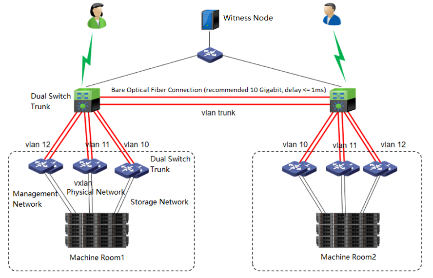
Introduction to HCI Stretched Cluster
Networking
The network topology of the HCI stretched cluster is as follows.
Networking Description:
- Machine Room 1 and machine Room 2
Machine room 1 and machine room 2 form an HCI cluster. Under the condition of ensuring the interconnection of the management network, VXLAN network, and storage network of the two machine rooms, configure corresponding redundancy strategies for the management network, VXLAN network, and storage network in the machine room. Stack the three networks with two switches, and configure corresponding network aggregation on the HCI cluster. The recommendations are as follows:
Management network: Each node is aggregated with 2 * GE network interfaces and stacked with two separate management network switches.
VXLAN network: Each node is aggregated with 2 * GE network interfaces and stacked with two separate VXLAN network switches.
Storage network: Each node is aggregated with 2 * 10GE network interfaces and stacked with 2 separate storage network switches.
The two machine rooms can set their own Edge. It is also recommended that the edge network adopt 2 * GE network interfaces for aggregation to provide services to the external network. If the conditions allow, providing the individual edge to the two machine rooms is suggested. If the conditions do not allow it, set the edge in the main service’s machine room.
-
Machine room network
Machine room 1 and machine room 2 are directly connected through the second layer of the network. It is recommended to use a 10 Gigabit bare optical fiber network for aggregation, and the network latency in the machine room should be less than or equal to 1 ms. The switches of the two machine rooms are stacked, and three different VLANs are divided on the stacked switches to carry the relevant data of the management network: the VXLAN network and the storage network of the two machine rooms. -
Witness Node
The witness node is important in the stretched cluster. It is different from the HCI system. To configure the witness node, you need to install the operating system of the witness node separately or purchase a separate aServer of the witness node. The regular communication between the witness node and the cluster shows whether the data copies in different computer rooms are abnormal and can be found in time. For the abnormal computer room, under the charge of the witness node, the business can continue to provide services in the computer room with normal data copies. The witness node can be deployed in the node room between machine room 1 and machine room 2 to carry services, or in a third-party site, provided that the witness node needs to be able to communicate with the HCI cluster IP. The link delay between the witness node and the cluster shall not be less than 5ms, and the recommended bandwidth is 100m.
Preparation Before Installation
Document and Tool Preparation
| Tool / Material Name | Download Path |
|---|---|
| Sangfor HCI Version User Manual | Sangfor Knowledge Base > Knowledge Base > Cloud Products > HCI > User Manual |
| Sangfor HCI version installation image | Sangfor Community > Self Services > Download > HCI |
| Sangfor witness node installation package | Sangfor Community > Self Services > Download > HCI |
| Sangfor aDeploy | Sangfor Community > Self Services > Download > Tools |
| Sangfor virtual network device template | Sangfor Community > Self Services > Download > HCI > NFV Contact Sangfor Support or Community Livechat to obtain if it is not available. |
| Operating System Image | Self-access |
| Chrome、UltraISO、MD5 | Self-access |
HCI Cluster Configuration Requirements
| Name | Project | recommended value | Precautions |
|---|---|---|---|
| Server | RAID Card | 1. Passthrough (JBOD, non-raid) mode must be supported. 2. The cache disk and data disk must be configured in passthrough mode. 3. RAID1 is supported. (used by the third-party service system disk). 4. Use aDeploy tool to check the compatibility of raid card and raid card firmware. Hardware that does not meet the requirements will not be allowed to add to virtual storage. |
Raid0 mode is prohibited for cache disk and data disk. |
| CPU | It is recommended that the CPU dominant frequency be greater than 2.0GHz. (server-level CPU is recommended). | 1. It is forbidden to use CPUs with less than 8 threads. 2. Support HCI deployment to servers equipped with Haiguang 7159 CPU. 3. If using Haiguang CPU: a. Mixed deployment is not supported, and only Haiguang CPU can be used in the same cluster. b. NUMA scheduling function is not supported. c. Heterogeneous migration is not supported. d. Windows virtual machine is prohibited from turning on the high-performance clock. |
|
| RAM | RAM shall not be less than 64G. | For Nodes with less than 32G RAM, aSAN, aNET, and aSV are prohibited from fully enabled. | |
| System disk | 1. Enterprise hard disk is recommended for system disk. 2. The capacity shall not be less than 128G. 3. The third-party service uses two disks to make RAID1. |
1. The server system disk is prohibited from deploying a single disk RAID0. 2. It is forbidden to use SD card as HCI system disk. The reason why it cannot be used is that it has problems in reliability, performance, and stability. |
|
| Data disk | Distributed storage uses SSDs as cache disks. SATA (or SAS) is used as the data disk. SSD: the higher the HDD capacity ratio, the better the overall performance. Use aDeploy tool to check the compatibility of SSD Firmware. If it does not meet the requirements, it will not be allowed to be added to virtual storage. |
1. Non enterprise HDD disks are prohibited. 2. It is forbidden to use HDD Hard Disks with 7200 rpm or less. 3. It is forbidden to use a hard disk less than 600G as a data disk. (4T and above is recommended) 4. 4Kn disks are prohibited for versions lower than 6.2.0 or 2 hosts virtual storage clusters. 4Kn disks are supported since version 6.2.0). 5. It is forbidden that the capacity ratio of SSD cache disk or HDD data disk is less than 1:20 (the recommended capacity ratio in best practice is 20%). 6. If a read-intensive SSD is used, the SSD cache disk or HDD capacity ratio cannot be less than 7%. 7. The SSD cache disk or HDD data disk ratio cannot be less than 1:6. 8. The sum of data disk capacity among nodes and the maximum capacity cannot exceed 80% of the sum of all remaining nodes. 9. Differences in the capacity of data disks in a single host are allowed, but the capacity difference between the largest and smallest data disks should not exceed 2 times. 10. Whether in the test or implementation stage, the number of cache disks cannot be greater than the number of data disks. 11. requirement The SSD interface rate is 6gbps. If the rate is 3gbps, it is not allowed to join the virtual datastore. 12. HDDs with a rate lower than 50MB/s are prohibited from joining the virtual datastore. 13. SSD data disks (flash) with IOPs less than 10000 are not allowed to join the virtual datastore. |
|
| Cache disk | VXLAN Administration Service switch |
1. Non enterprise SSDs are prohibited. 2. The cache disk cannot use SSDs smaller than 240GB. 3. SSDs with DWPD less than 1 are prohibited (the spec parameter table of SSD can be found). 4. Do not use SSDs that do not support power-down data protection. 5. SSDs with IOPs less than 30000 are prohibited from joining the virtual datastore. |
|
| Switch | VXLAN Administration Service switch |
Support Stack/M-LAG and the VXLAN switch support jumbo frames (adjust MTU value). Disable the selection of switches that do not support jumbo frames. (some vendors call it MTU interface). |
|
| Storage switch | A 10 Gigabit switch must be used. | Gigabit switches are prohibited for private storage networks. |
Witness Node Configuration Requirements
Hardware Configuration Requirements
When deploying a stretched cluster, you need to deploy a witness node. The witness node can be deployed on a physical server or a VMware virtualization environment. You can refer to the following table for corresponding hardware planning according to the cluster size.
Note:
The arbitration disk does not support the use of mechanical disks. It must be an enterprise SSD and in the compatibility list. Otherwise, it cannot pass the checking.
| Cluster size | Minimum hardware requirements | Illustration |
|---|---|---|
| Small deployment (4 to 6 HCI nodes, 2 to 3 for each machine room) |
CPU: 6 cores Memory: 32GB System disk: capacity > = 128G Quorum disk: enterprise SSD with capacity > 100GB. Virtualization deployment requires no less than 1000 IOPs. |
Support VMware virtualization deployment and physical machine deployment. |
| Midsize deployment (8 to 16 HCI nodes, 4 to 8 for each machine room) |
CPU: 8 cores Memory: 32GB System disk: capacity > = 128G Quorum disk: two 128GB or 248GB enterprise SSDs are used and configured as RAID1 |
Physical machine deployment is recommended. |
| Large deployment (18 to 24 HCI nodes, 9 to 12 for each machine room) |
CPU: 16 cores Memory: 32GB System disk: capacity > = 128G Quorum disk: two 128GB or 248GB enterprise SSDs are used and configured as RAID1 |
Be sure to deploy using physical machines. |
Switch Configuration Requirements
Basic Configuration Requirements
-
Management, service, storage, tunnel, etc., adopt different VLAN isolation based on Security compliance considerations.
-
Turn off STP protocol.
-
Turn on the VXLAN interface jumbo frame.
-
Turn off the IGMP snooping on the switch connected to the management network and the VXLAN network.
-
The aggregation interface end-to-end switch in the active and standby mode does not need to be configured with aggregation.
Specific Configuration Examples
| Network type | Interface type | Example (Configuration in Interface View) | Remarks |
|---|---|---|---|
| Management network | access | Interface Ethernet1/0/48 switchport access VLAN 2 |
– |
| Storage network | access | Interface Ethernet1/0/48 switchport access VLAN 3 |
– |
| Tunnel network | access | Interface Ethernet1/0/48 jumboframe enable switchport access VLAN 4 |
The tunnel interface needs to turn on the jumbo frame |
| External network | trunk | Interface Ethernet1/0/48 switchport mode trunk switchport trunk allowed VLAN 10-20 |
– |
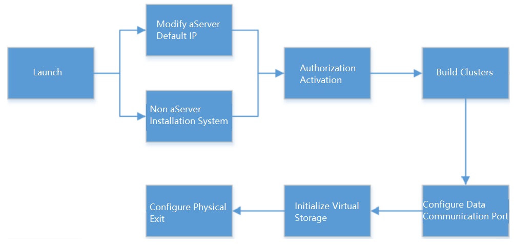
Introduction to Installation Process
The HCI cluster installation process is outlined in the figure below.
HCI Virtualization System Installation
aServer
The aServer has pre-installed the HCI operating system and set the eth0 interface as the management interface. The default IP address is 10.250.0.7/24. Use a PC to configure the IP address of the same network segment, connect directly to the eth0 port, and open it with a browser https://10.250.0.7/. Then, you can log in to the console of the aServer.
The default administrator account and password are admin. You will be prompted to change the default password when you log in for the first time. You will be forced to change the default password after a month.
After the first successful login, you will be prompted to modify the default IP address. If there are multiple aServer nodes, you need to log in separately to modify the default IP address before forming a cluster, and the IP address must be in the same network segment.
The aServer is signed and can only use the signed disk (shipped from the original factory). If the aServer is inserted into a third-party disk, it cannot be recognized in virtual storage and can only be used for local storage.
When virtual storage is used, node deletion is not supported. Taking the node out for separate use is forbidden after the cluster is disassembled.
The aServer cannot reinstall the system. After reinstalling the system, you need to re-sign the node and disk.
Do not perform a low-level format on the aServer disk. Re-sign is required after formatting.
Please refer to the BIOS Configuration Requirement section below for the configuration of the IPMI interface.
Third-Party Server
The third-party server installation system can use IPMI for ISO and USB flash disk installation. The main difference between the two methods is in the image mounting. The installation part is the same.
Server Configuration
Hardware configuration requirements
When installing HCI using a third-party server, each host hardware must meet the following minimum configuration requirements. Selecting the server hardware according to the recommended configuration is recommended to ensure the best effect.
Note:
Suppose you need to use the virtual storage function and the system disk. Each node must also be configured with at least one 240GB enterprise SSD (must support TRIM/Discard instructions) as the cache disk and several 1TB enterprise HDDs (RPM greater than or equal to 7200rpm) as the data disk.
The ratio of SSDs to HDDs shall not be less than 1:6, and the minimum ratio shall not be less than 1:25. If it is a read-intensive SSD, the ratio of SSD cache disk/HDD capacity shall not be less than 7%.
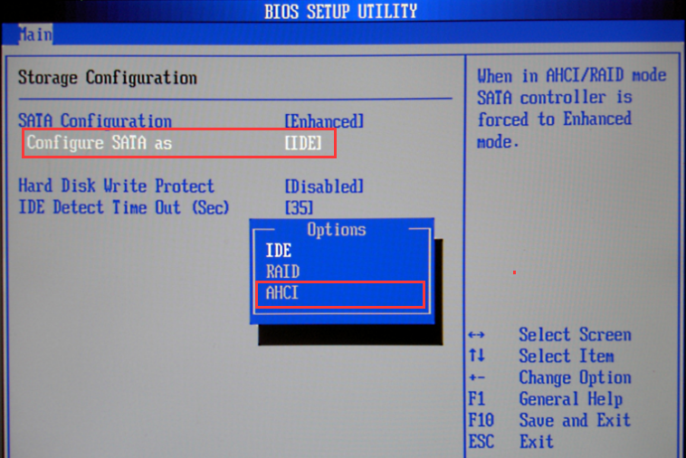
RAID Card Configuration Requirements
If there is a raid card, it is recommended to select a RAID card that supports JBOD / non-RAID passthrough and supports transparent transmission of trim instructions. If the RAID card does not support JBOD / Non-RAID, disable the raid card directly and enable normal disk mode (AHCI / IDE).
BIOS Configuration Requirement
When using a third-party server, you need to modify some BIOS options to ensure the efficient operation of the HCI platform. BIOS configuration requirements:
-
BIOS time synchronization
-
Enable VT-x or VMX
-
Turn Off Energy Saving Mode
-
Turn on power on self start
-
Configure IPMI address (optional)
Specific Configuration Examples
The method of entering BIOS is defined by the BIOS vendor. Usually, when the server is powered on and started, the screen will prompt to press del, ESC, F10, F11, and other keys to enter the BIOS Setup interface.
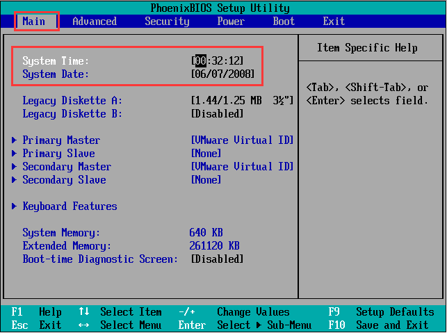
- BIOS Time Synchronization
The BIOS time of the server will be read as the system time when installing the hyper fusion platform. If the system time is inaccurate, the operation of some services may be affected. Therefore, you first need to modify the BIOS time to the current time.
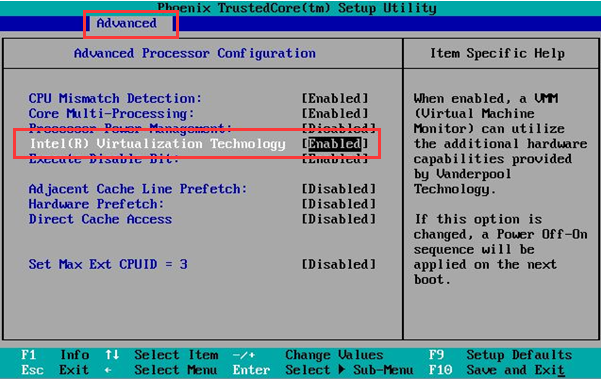
- Enable VT-x
When the HCI runs the virtual machine, the host is required to support the hardware-assisted virtualization technology of Intel VT-x. Therefore, in addition to the CPU supporting VT-x technology, you also need to enable this function in BIOS. If the CPU does not support VT-x, or VT-x is not enabled in the BIOS, the hyper fusion platform cannot be successfully installed.
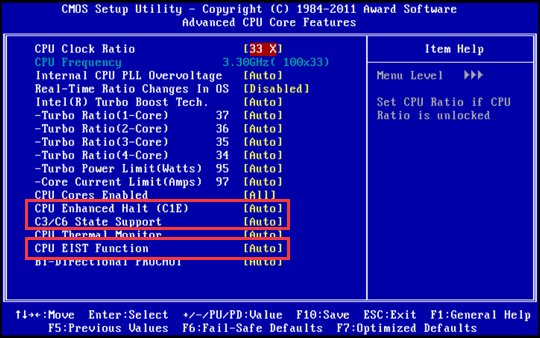
- Turn Off Energy Saving Mode
Turn off the CPU energy-saving mode (disable EIST, CPU Status, and other options). The names may differ according to the hardware (such as PowerPperformance).
| CPU Status | Status interpretation | Status type | Use suggestions |
|---|---|---|---|
| C0 | Operating State | The normal working state of CPU. | —- |
| C1 | Halt | It is recommended to disable CPU sleep states at different levels and depths. | Disable |
| C1E | Enhanced Halt | It is recommended to disable CPU sleep states at different levels and depths. | Disable |
| C2 | Stop Grant/Clock | It is recommended to disable CPU sleep states at different levels and depths. | Disable |
| C2E | Extended Stop Grant | It is recommended to disable CPU sleep states at different levels and depths. | Disable |
| C3 | Sleep | It is recommended to disable CPU sleep states at different levels and depths. | Disable |
| C4 | Deeper Sleep | It is recommended to disable CPU sleep states at different levels and depths. | Disable |
| C4E/C5 | Enhanced Deeper Sleep | It is recommended to disable CPU sleep states at different levels and depths. | Disable |
| C6 | Deep Power Down | It is recommended to disable CPU sleep states at different levels and depths. | Disable |
| EIST | Enhanced Intel SpeedStep Technology |
Automatically adjust the voltage and frequency of the processor. | Disable |
- IPMI Address Configuration
Log in to the BIOS interface, select Server MGMT >BMC Network Configuration >BMC IPv4 network configuration / BMC IPv6 network configuration, and press enter to view the configuration of current BMC IPv4 and BMC IPv6 network parameters.
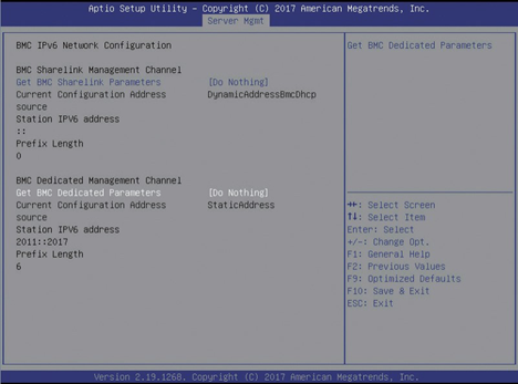
BMC Sharelink is the first interface that multiplexes IPMI addresses on the NIC. BMC dedicated is the address configured for a separate IPMI interface. When configuring the out-of-band management network, modify BMC dedicated and select manual to write the static address manually.
USB Flash Disk Installation
Precautions
-
UltraISO should be the latest version.
-
The writing format of the USB drive should be USB-HDD or USB-HDD+. Click Verify to check whether the image file is written correctly.
-
USB drive capacity should be greater than the size of the ISO file.
-
The server configuration and switch configuration shall meet the configuration requirements of the server and switch in Chapter 2.2 Preparation Before Installation.
Steps
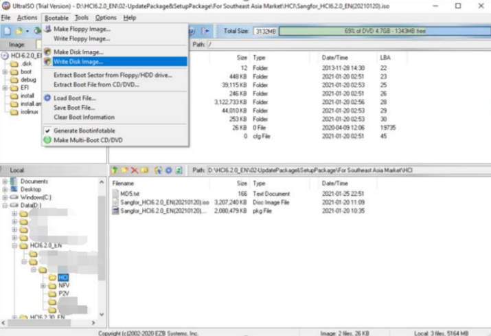
- First, insert the USB flash disk into the personal PC, then open the software UltraISO, select File > Open, and load the ISO file of Sangfor HCI software from the local disk.
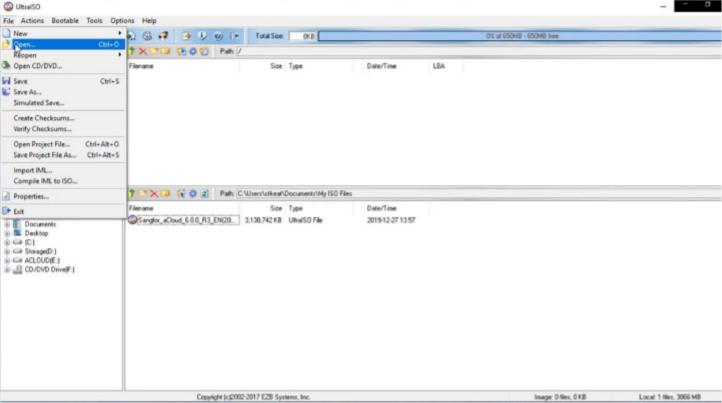
-
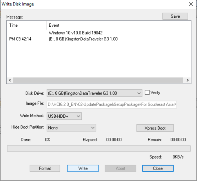
Select Bootable > Write Disk Image and choose the USB drive into which you want to write the image file. Then, click the Write button and keep others’ settings unchanged.
You can remove the USB drive after the image file is written to the USB drive.
- The target of writing is USB flash disk or optical disc. Be sure to check Verify. The write method (usually USB-HDD+) is determined according to the USB startup type supported by the server.
- Insert the USB flash disk into the third-party server and boot from the USB flash disk in BIOS.
- Enable Virtualization Technology in BIOS, as shown below.
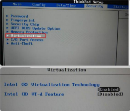
Note:
BIOS settings vary from computer to computer.
Witness Node System Installation (Optional)
Configuration Requirements
Refer to Chapter 2.2.3 Witness Node Configuration Requirements.
Sangfor aServer
Sangfor aServer has been pre-installed Sangfor HCI operating system and configured with a management interface(eth0, default IP address:10.250.0.7/24). To access the Web admin console of the Sangfor HCI platform on a PC. First, configure the PC with an IP address on the same network segment with that management interface and connect it to the eth0 interface on the aServer. Then open your browser and enter https://10.250.0.7/ into the address bar to log in to the Sangfor HCI platform console.
The default username and password are admin. The administrator will be prompted to change the default password upon first login. If the default password has not been changed for one month, the system will force the administrator to change it.
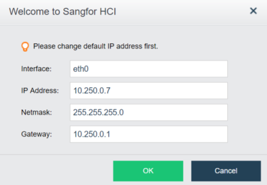
Upon the first login, the administrator will be prompted to modify the default IP address of the management interface, as shown below. If multiple aServers are deployed in the network, the default IP address of the management interface on each aServer needs to be modified, and addresses of management interfaces must be on the same network segment.
Third-Party Server
Description
The witness node can be either a Sangfor aServer or a third-party server. This chapter describes how to install the witness node on the third-party server.
Precautions
- It can be installed by ISO or USB flash disk. For preliminary preparations such as USB flash disk, please refer to Chapter 2.4.2.2 USB Flash Disk Installation.
- If there is a need for cluster expansion in the future, you can also adjust the configuration of the witness node accordingly.
Prerequisites
The hardware configuration of the witness node shall meet the configuration requirements in Chapter 2.2.3 Witness Node Configuration Requirements.
Steps
-
If ISO installation is adopted, load the arbitration installation package and select start from IPMI. If the USB flash disk is used for installation, use the USB flash disk made by the arbitration installation package to start.
Select Install Sangfor HCI on this machine, and then press ENTER to enter the installation page.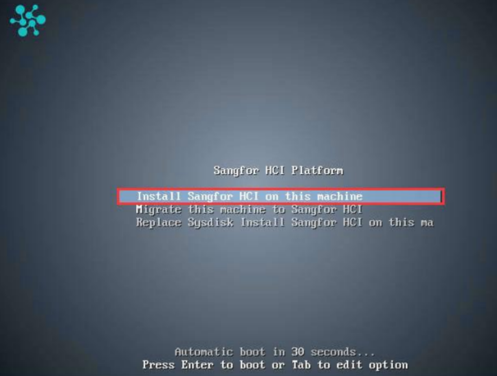
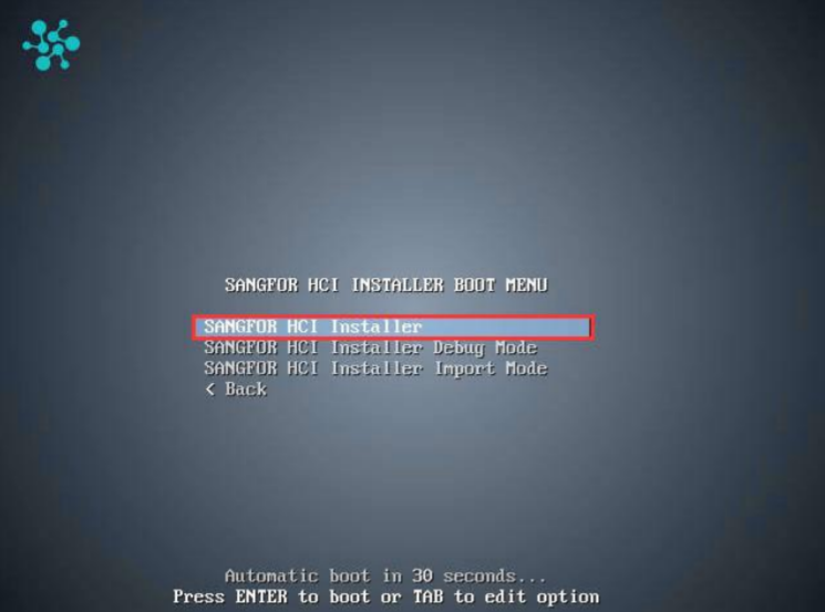
-
Select Sangfor HCI Installer and press ENTER to begin the installation.
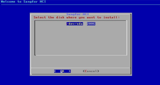
- Select a disk where you want to install Sangfor HCI software and select OK. If there is only one disk, you can select OK directly.
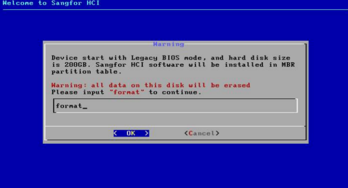
- After selecting the disk, you will be prompted to format the disk. Input format to confirm formatting disk, and select OK to continue the installation. After you select OK, the Disk Speed Tester page will appear. To test disk speed, select Yes. To skip this step, select No.
- After installing the Sangfor HCI software, you will be prompted to select an Ethernet interface and configure an IP address for that interface.
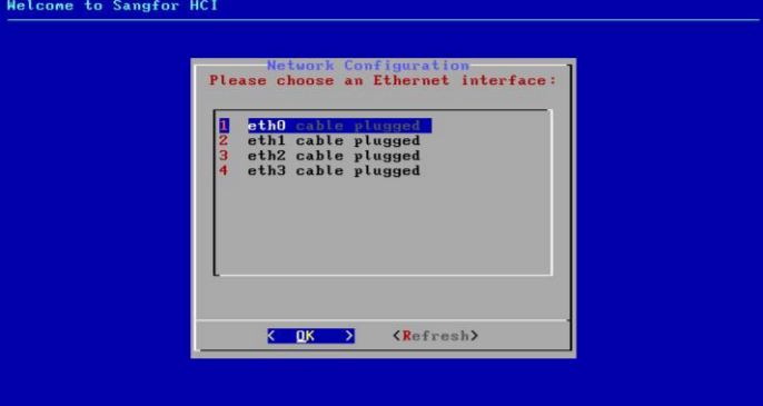
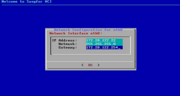
- Select an Ethernet interface, set the IP address, netmask, and gateway address, and then click OK.
-
After the selected interface is configured, you can choose whether to continue to configure another interface. Select Yes to return to the network configuration page or No to finish the installation.
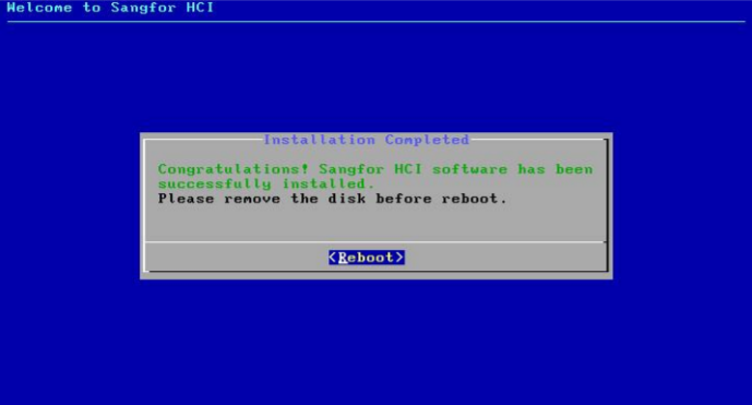
-
After the installation completes, remove the USB drive and then select Reboot to restart the server.
- The browser logs in to the web admin console page of HCI through the URL address: https://
<configured IP>.
Service Packs
Service Packs Settings
Description
Online Service Packs (SP) service can regularly obtain the latest patch information from the online patch platform to ensure the stability and security of the server.
HCI with internet access can directly access the Sangfor online SP center platform to update the latest patch. HCI in the intranet without internet access. If the VM has internet access, it can use the Sangfor proxy VM to access the online SP center. HCI and VM without internet access can use the third-party proxy server to access the online SP center. You can also deploy the on-premises sangfor SP server in the intranet for SP updates.
Precautions
- After configuration, the patch service must test connectivity to ensure that the HCI platform can connect to the online SP center.
- It is not recommended that the HCI management network directly access the online patch service platform as HCI will be exposed to the public network.
- When using the Sangfor proxy VM to access the online SP center, do not modify the virtual machine name (the default name is: _sangforaoperation_vmworkstation) after importing the VM. Otherwise, the agent service will become invalid.
Prerequisites
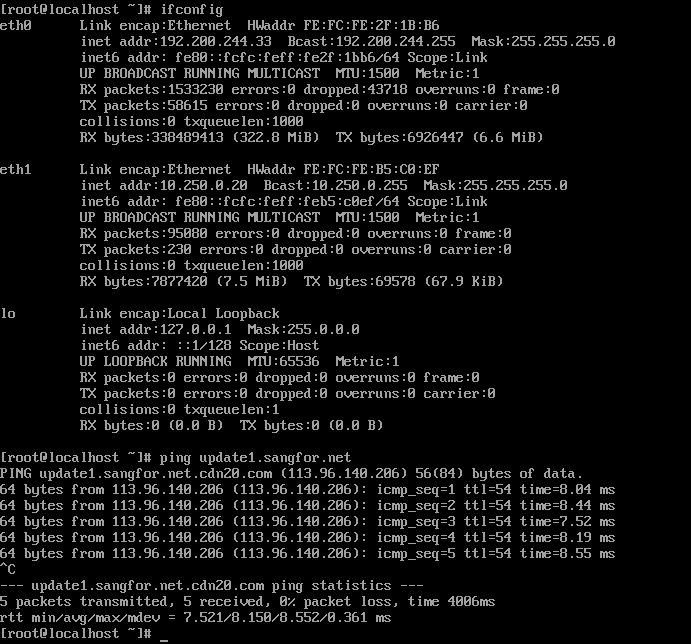
The customer network needs to allow connection for the online SP center addresses to ensure that the HCI platform can access the online SP center.
Steps
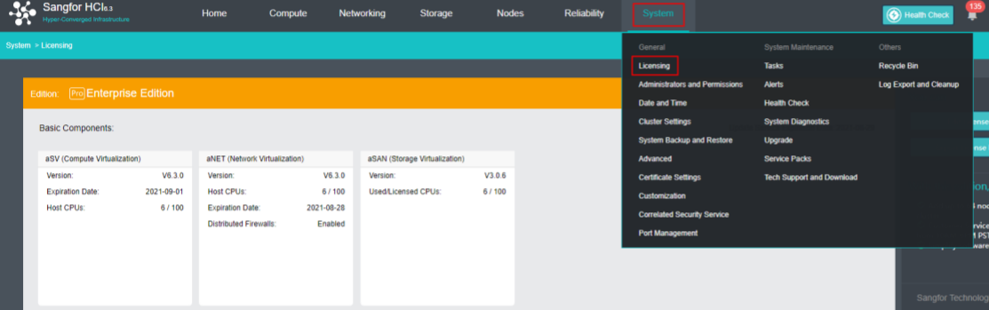
- Navigate to System > Service Packs and click the Settings tab.
- Click on the SP Center Addresses to ensure that the SP center addresses have been allowed connection to the customer network. The table below lists the addresses along with the purpose and requirements.
| SP Center address | Purpose | Requirements |
|---|---|---|
| https://cloudbgcop.sangfor.com | Cloud SP Server | It must be allowed |
| http://update1.sangfor.net | Online SP Center | At least one should be allowed, and it is recommended to allow multiple. |
| http://update2.sangfor.net | Online SP Center | At least one should be allowed, and it is recommended to allow multiple. |
| http://update3.sangfor.net | Online SP Center | At least one should be allowed, and it is recommended to allow multiple. |
| http://121.46.26.221 | Online SP Center | At least one should be allowed, and it is recommended to allow multiple. |
-
Check the Enable online SP Service checkbox.
-
Check the I have read and accept Data Processing Agreement checkbox.

- According to the HCI deployment scenarios and network conditions, select an appropriate online platform communication mode for the setting. (after selecting the corresponding scene for configuration, skip other scenes directly to step 6 for configuration).
Scenario 1: Access the online patch platform directly.
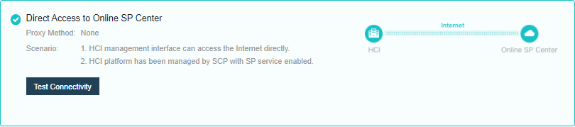
- Select Direct Access to Online SP Center for communication mode settings, test the connectivity, and save the settings.
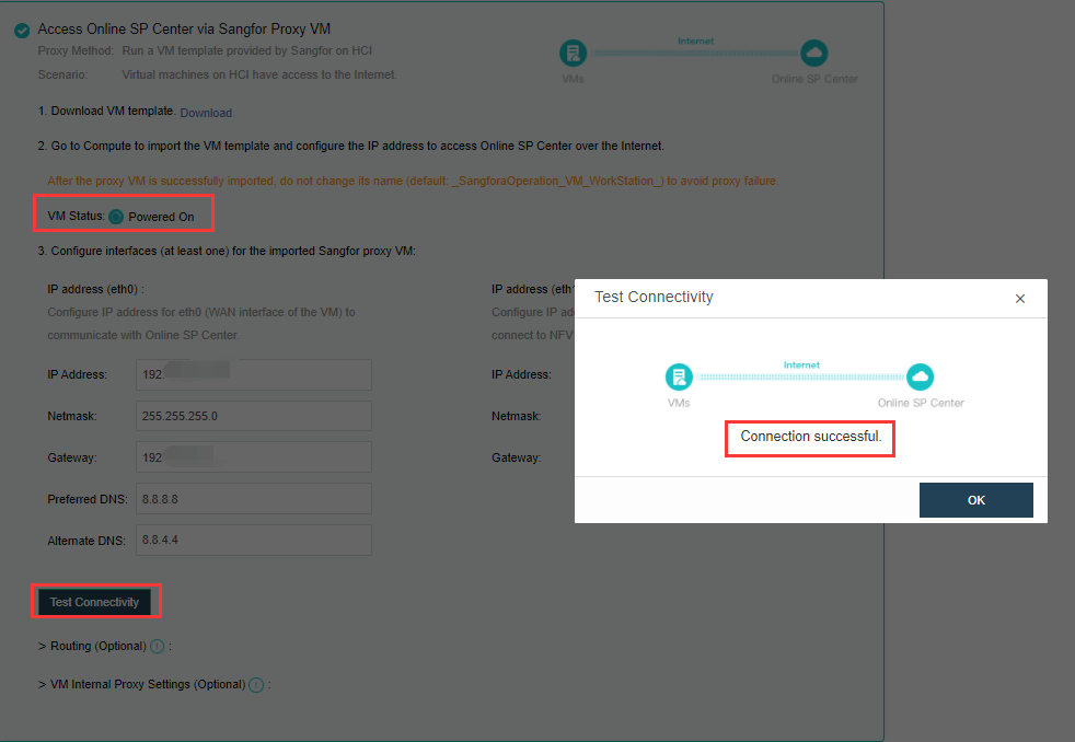
Scenario 2: HCI platform cannot be networked, but networked virtual machines can be deployed on HCI.
-
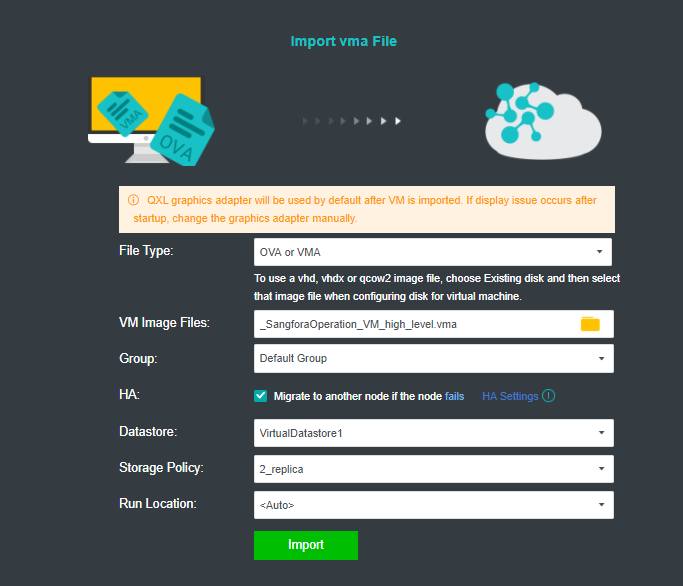
Download the virtual machine template.

-
Import the downloaded VM template into HCI. When importing the template, it is recommended to configure it as follows:
a. HA: Enable the HA.b. Datastore: Shared datastore for all nodes, for example, virtual storage.
c. Run location:
<Auto>
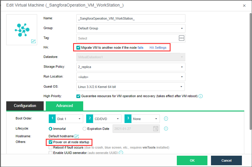
- Edit the virtual machine, click Advanced, and confirm that HA is enabled and the Power on at node startup checkbox is checked.
-
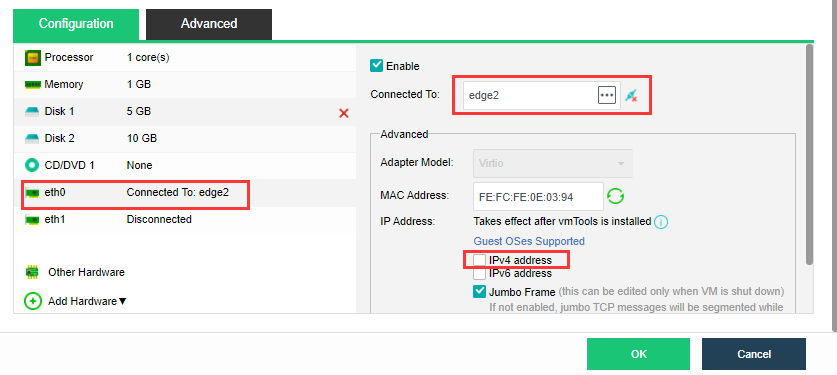
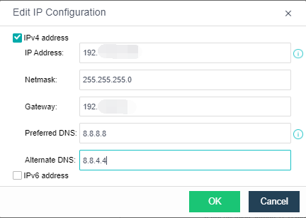
Configure the virtual machine eth0 to connect to the edge, and ensure that the edge can access the external network. Modify the IP settings on the page, configure the planned address to the virtual machine, and start the virtual machine.
-
As shown in the figure below, configure eth0’s IP, netmask, gateway (optional), preferred DNS (optional), alternative DNS (optional), test connectivity, and ensure the IP Access to the online SP center. (Eth1 is the internal interface of the proxy virtual machine. If there is an NFV device, you need to configure the eth1 interface to connect to the NFV device. The configuration method refers to the configuration of the eth0 port to connect to the network where the NFV device is located).
Scenario 3: the HCI platform has no internet connection, but it can access the internet through a third-party agent.
-
The network deployment is shown in the figure above. This scenario selects a third-party proxy server to access the online patch platform.
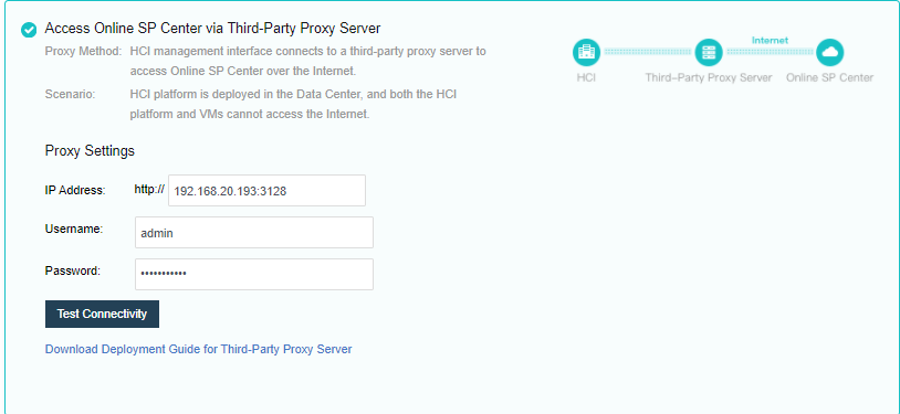
-
Click Download Deployment Guide for Third-Party Proxy Server. The downloaded content is a compressed package named Proxy_Squid_Deployment_Guidance.rar, containing document descriptions, recommended agent installation packages, and configuration files.
-
Refer to the downloaded configuration guide, install and configure a third-party agent program on the proxy server, and confirm that the server can access the Sangfor online SP server. Deploy two interfaces as shown in the figure below, one can access the Internet to connect to the Sangfor SP server, and the other can access the HCI in the intranet.
-
Fill in the address (IP + port, example: 10.250.0.20:3128) of the agent set in step 2 on the HCI platform. And the authentication user name and password of the agent are set during the deployment of the proxy server.
-
The IP address is the proxy server intranet port IP.
-
The port is the publishing port of the agent service. The default is 3128.
-
Click Test Connectivity, and confirm that the network is connected.
- Set the security component (aSEC) patch service (optional), and select Use the same communication method as that configured on HCI.

- Save the settings by clicking the Save button.
HCI Cluster Initialization
HCI Cluster Initialization Conditions
Whether creating a normal cluster or a stretched cluster, in the cluster initialization process of HCI, the authorization activation, cluster formation, and Overlay Network Interface configuration are the same. You need to set up the network according to the installation networking requirements in Chapter 2.1 Networking Installation Introduction, and then initialize the cluster, including authorization activation, cluster formation, and Overlay Network Interface configuration. Then configure virtual storage according to the actual situation, and create ordinary volumes or Stretched datastores.
HCI Cluster Initialization Has The Following Conditions
- Sufficient licenses need to be purchased according to the number of CPUs of all nodes in the cluster.
- A single node does not support virtual storage. An ordinary cluster requires at least two or more nodes in the cluster. If you need the striping function of virtual storage or the multi-volume function of virtual storage, you need three or more nodes in the cluster.
- The stretched cluster starts with at least four nodes, plus one witness node. In the actual deployment, ensure that the node location configured on the page is consistent with the actual physical location. Otherwise, it cannot play the role of machine room-level protection. The two fault domain computer rooms must be connected on the second floor. The link of the witness node does not need to be connected to the second floor but only needs to be reachable by the network.
- If you do not use virtual storage but external storage as the storage of the cluster, the external storage you need to use supports sharing (multiple nodes access at the same time) and VAAI features (mainly ats attributes). Otherwise, shared storage cannot be added.
- The production environment and test environment are recommended for building different clusters independently.
- It is recommended that there should be no more than 24 nodes in a single cluster.
- HCI deployment on a single host is prohibited.
- Licensing Check: If the validity period of the licensing is less than one year, remind the user to renew in time.
- Health Check: Must run health check after implementation to eliminate all fault risk items.
- aDeploy tool detection: Must run aDeploy tool after implementation to eliminate all fault risk items.
Licensing Activation
Steps
- Insert a USB key containing license key information into the cluster controller, and then go to System > General > Licensing, as shown below:
- To input the license key, navigate to Edit License Key > Import License Key File.
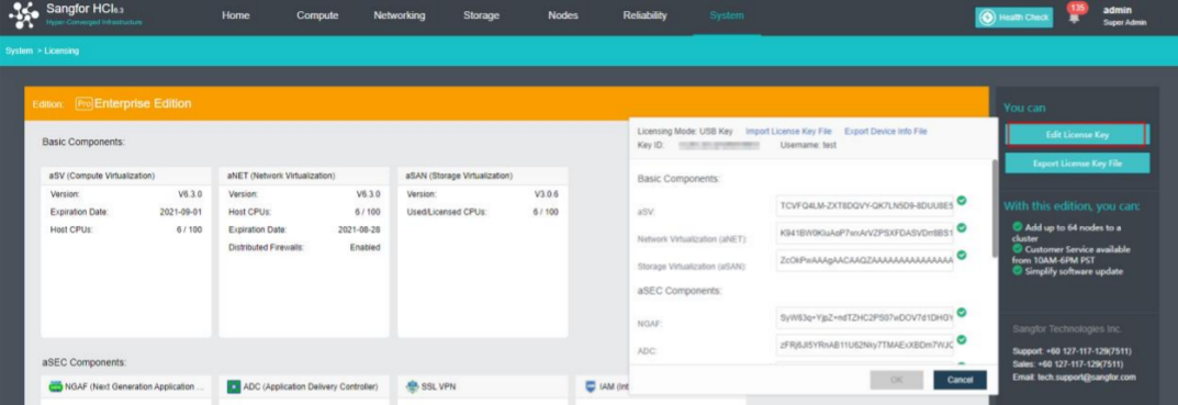
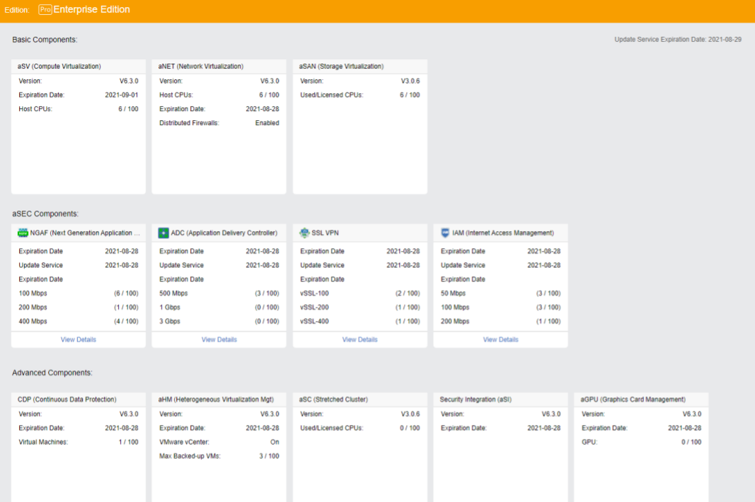
- After clicking OK, you can check the license information on the left panel to determine whether the license key is activated successfully, as shown below:
Cluster Formation
Configure Cluster IP
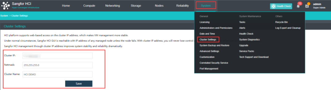
Cluster IP manages virtual machine resources through cluster IP after the node is offline and configures cluster IP through System > General > Cluster Settings.
Note:
Note that cluster IP address and node NIC address cannot be the same, or it will result in IP address conflict.
Configure Cluster Time
Steps
- Click System > Date and Time in the console to enter the page to compare whether the HCI cluster time is accurate. If the time is inaccurate, click Change to enter the platform time setting page.
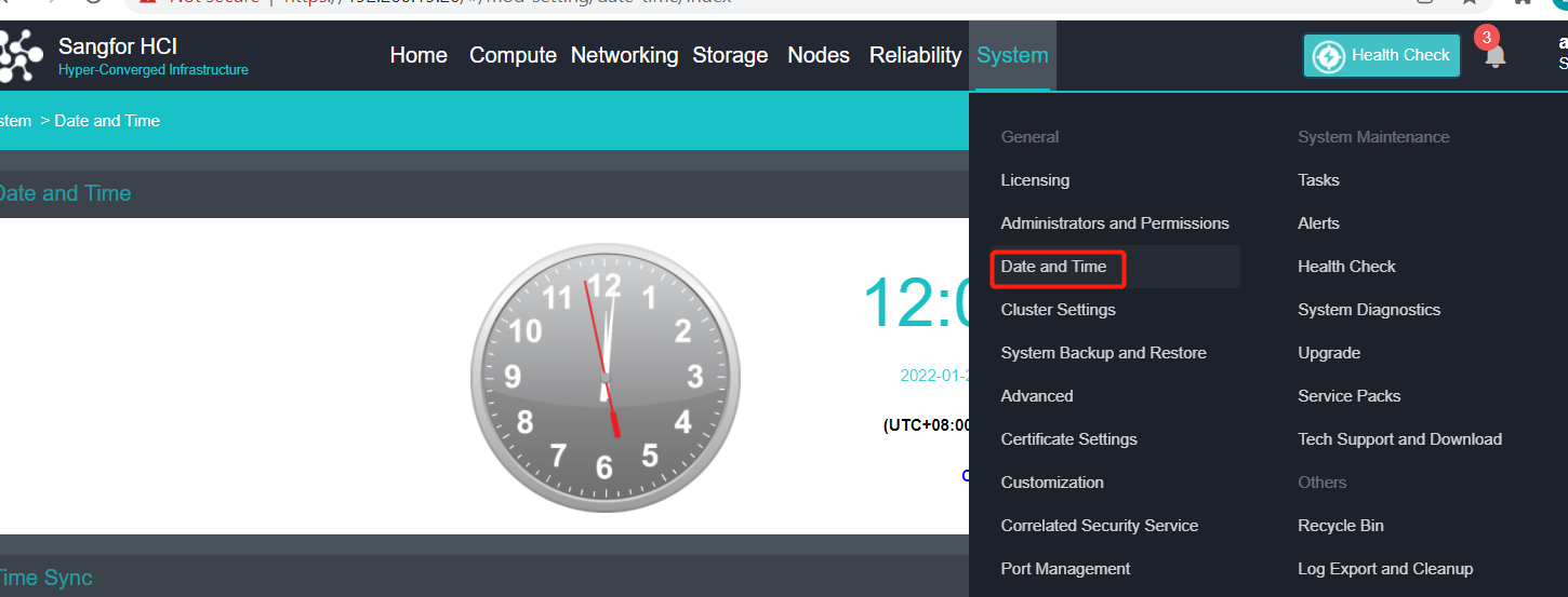
- To modify the cluster time, you can fine-tune the time by clicking the up or down arrow or configure the platform time by obtaining the local computer’s time. You can also modify the time zone of the platform.
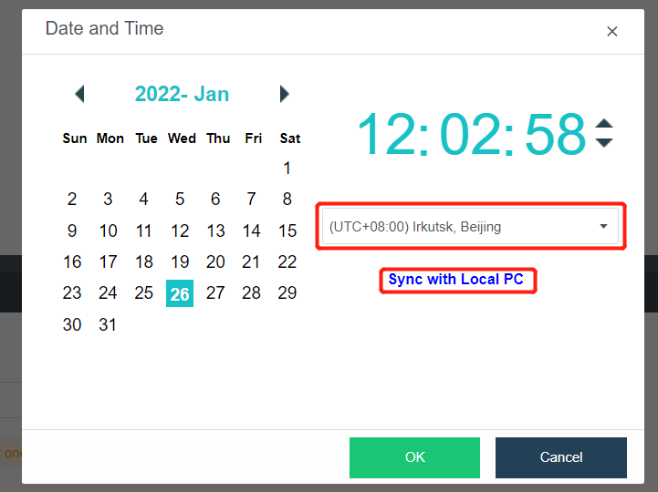
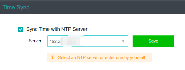
- If the platform time is synchronized with the internal NTP server, you only need to check the Sync Time with NTP Server checkbox, modify the server’s IP address, and click Save.
Configure Alert Notification (Optional)
Steps
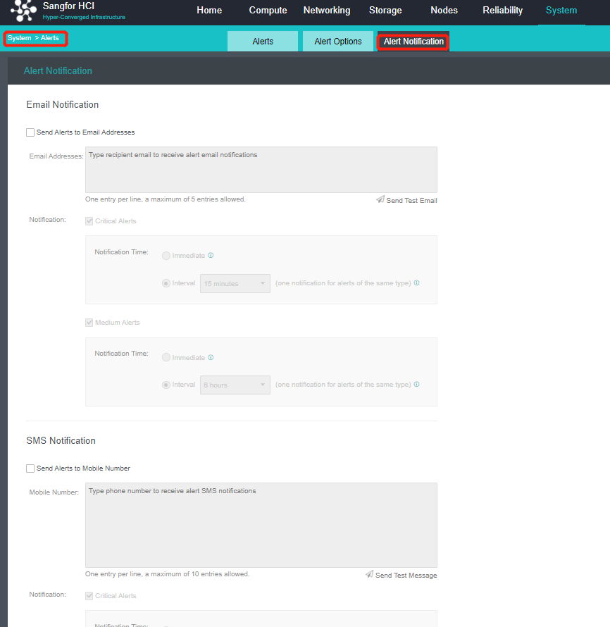
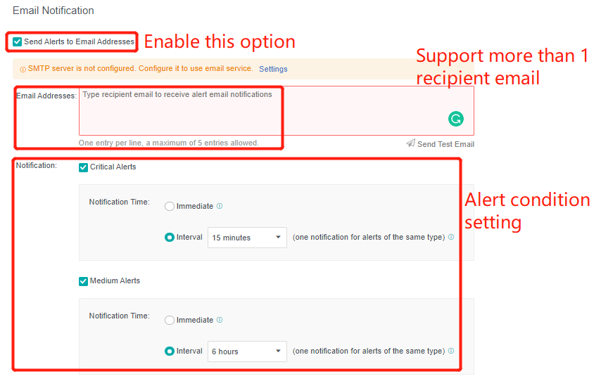
- Enter the configuration interface: open the console and enter System > Alert > Alert Notification. Check the Send Alerts to Email Addresses or Send Alerts to Mobile Number checkbox as required. Before setting, you need to set up a mail server or SMS server.
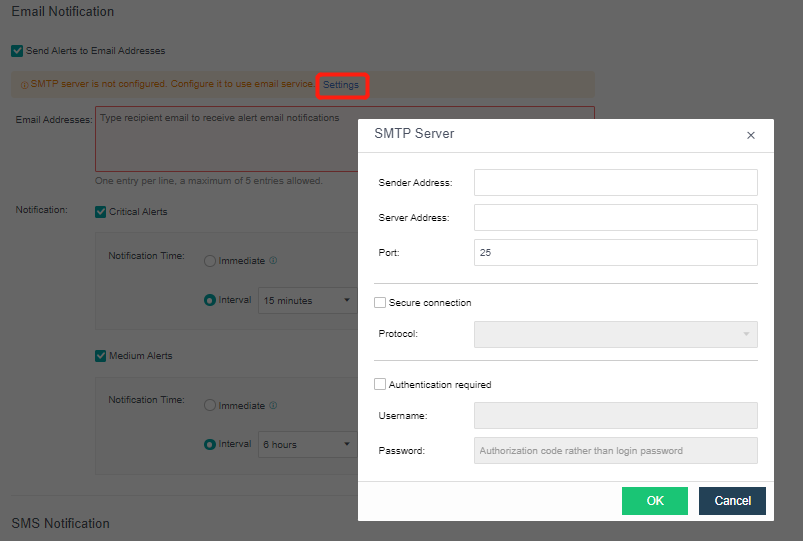
- Send to the specified mailbox: Check the Send Alerts to Email Addresses checkbox. If the mail server is not configured, click Setting. If the configuration already exists and needs to be modified, click Edit. Fill in the configuration information of the Mail server and click OK to save the settings. Fill in the email address that can be delivered by the mail server as required, set the condition for triggering the alarm notification as needed, and click Save to complete the configuration.
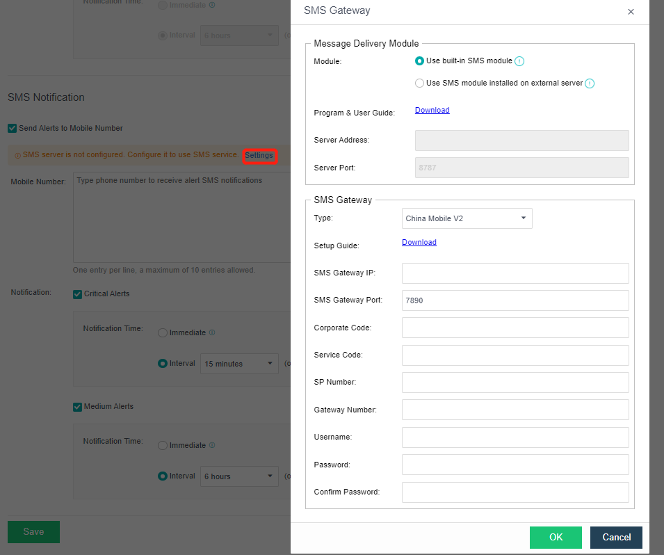
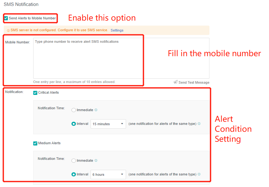
- Send to specified mobile phone number: check the Send Alerts to Mobile Number checkbox. If the SMS server is not configured, click Setting. If the configuration already exists and needs to be modified, click Edit. Fill in the configuration information of the SMS server and click OK to save the settings. When there is a problem with the SMS server configuration, you can download the guidance document by clicking the Download button. Fill in the mobile phone number of receiving SMS as required, set the conditions for triggering alert notification as required, and click Save to complete the configuration.
Add Node
Precautions
- For a cluster size of more than 24 nodes, it is recommended to use the hardware with good performance as the cluster controller of the control node.
- When two nodes are expanded to more than three nodes, the virtual machine must be shut down because an arbitration mechanism needs to be established.
- The first added node within the three nodes must be a control node and in the control node pool. Other hosts can choose whether to join the control node pool.
Steps
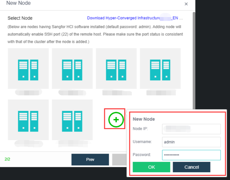
- Navigate to Nodes > HCI Cluster > Nodes. You can add a node to a cluster by clicking Add New Node.

- On the following page, select a node you want to add to the cluster and input the corresponding username and password. Once a node is chosen, the node icon turns green, indicating the node can be added to the cluster. There will be a prompt to reconfigure the firewall configuration of the added node and execute the node addition task.
Configure Controller Node Pool
Description
In the HCI cluster, the node has the roles of control node and non-control node. The control node can provide cluster management and computing, network, storage, and other functions, such as virtual machine scheduling, task scheduling, etc. The non-control node can provide computing, network, storage, and other functions. The controller node pool is set to achieve high availability of cluster management nodes. When the control node fails, other nodes can be selected as the control node in the controller node pool to realize high availability switching and ensure the normal use of cluster management functions.
Precautions
-
For a cluster size of more than 24 nodes, it is recommended to use the hardware with good performance as the cluster controller.
-
The cluster supports up to three control nodes.
-
The cluster controller can only switch in the control node pool. If all the control nodes fail, there is no cluster controller.
Steps
- Navigate to Nodes and click Configure Controller Node Pool to add a node into the controller node pool.
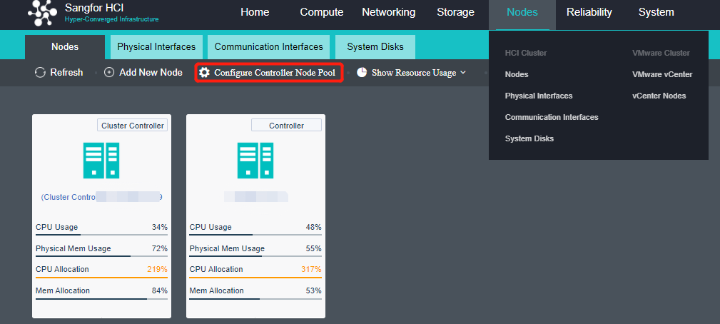
- Add the control node into the control node pool and set three active nodes.
Manage Communication Port Configuration
Scenario
It is recommended to use the aggregation interface as the management communication port to increase the bandwidth and improve the network stability of the platform.
Precautions
- The peer switch needs to configure the corresponding interface aggregation mode when using the aggregation interface. Otherwise, the network will be blocked, and the HCI management interface cannot be logged in.
- The aggregation of the network interface is not supported.
- Direct aggregation of two interfaces with different roles is not supported. Aggregation can be performed after canceling one interface role. For example, eth0 (management interface) and eth1 (VXLAN interface) cannot be aggregated directly. The VXLAN interface can be adjusted to eth2. At this time, eth0 (management interface) and eth1 (no role) can be aggregated.
Steps
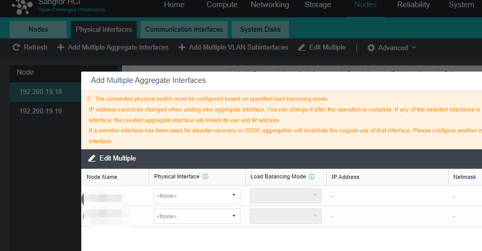
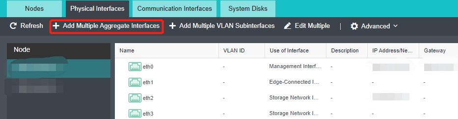
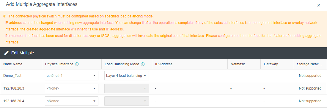
- Click Nodes > Physical Interface on the HCI console, click Add Multiple Aggregate Interfaces, and select two interfaces. The aggregation mode recommends loading according to MAC or IP address.
- Click Nodes > Communicate Interface in the HCI console. Among the four interface roles, click Management Interface, click Setting to enter the configuration page, and select the management interface as the added aggregation port.
Overlay Network Interface Configuration
Precautions
-
After deploying the HCI cluster, you need to specify an Overlay Network Interface for each node. The Overlay Network Interface shall use Gigabit (or 10 Gigabit) interface and be interconnected by Gigabit (or 10 Gigabit) switch. (When only two nodes exist, the Overlay Network Interface can be connected directly). To improve the interface bandwidth and redundancy of the Overlay Network Interface, it is recommended to configure the aggregation interface as the Overlay Network Interface. At this time, the opposite end switch needs to configure the corresponding aggregation mode.
-
The Overlay Network Interface is configured as a multiplex cluster management port by default. To obtain high network forwarding performance, it is recommended to set the management communication port and Overlay Network Interface (VXLAN) to different interfaces.
-
Direct aggregation of two interfaces with different roles is not supported. Aggregation can be performed after canceling one interface role. For example, eth0 (management interface) and eth1 (VXLAN interface) cannot be aggregated directly. The VXLAN interface can be adjusted to eth2. At this time, eth0 (management interface) and eth1 (no role) can be aggregated.
Steps
- Click Nodes > Physical Interface on the HCI console, click Add Multiple Aggregate Interfaces, and select two interfaces. The aggregation mode recommends loading according to MAC or IP address.
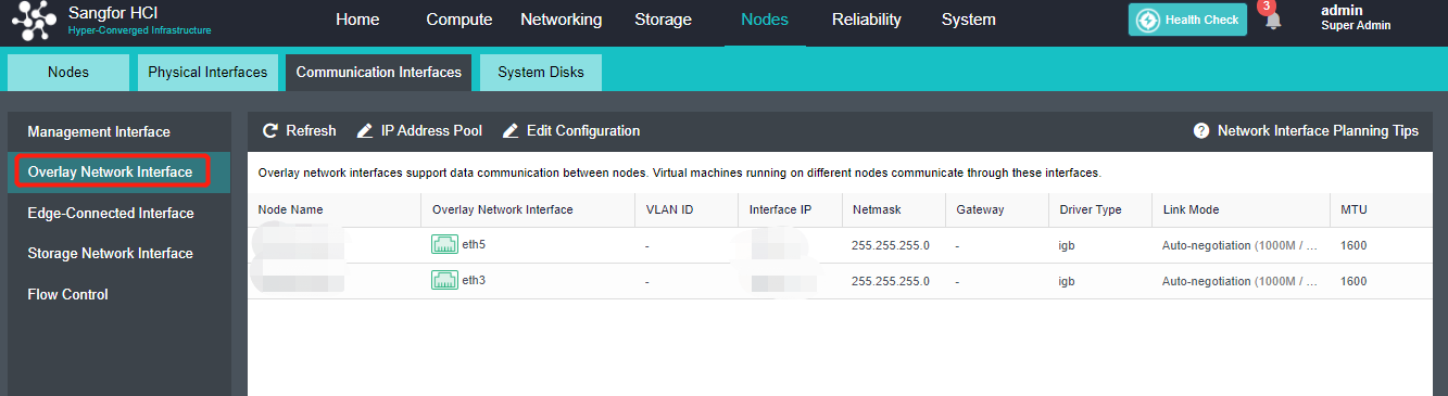
- Click Nodes > Communication Interface in the HCI console. Find the Overlay Network Interface among the four interface roles and click Edit Configuration to enter the configuration page to modify the Overlay Network Interface.
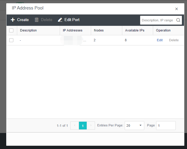
- Click Nodes > Communication Interface in the HCI console. Find the Overlay Network Interface among the four network port roles and click IP address Pool to enter the configuration page to modify the VXLAN IP pool.
-
Create: a VXLAN IP pool can be created. Multiple VXLAN IP pools can exist in a cluster. A node is only allowed to join one VXLAN IP pool.
-
Delete: You can delete the VXLAN IP pools that are no longer in use.
-
Edit Port: The port number used for VXLAN can be modified. The port number supports 8472, 4789 and 4790.
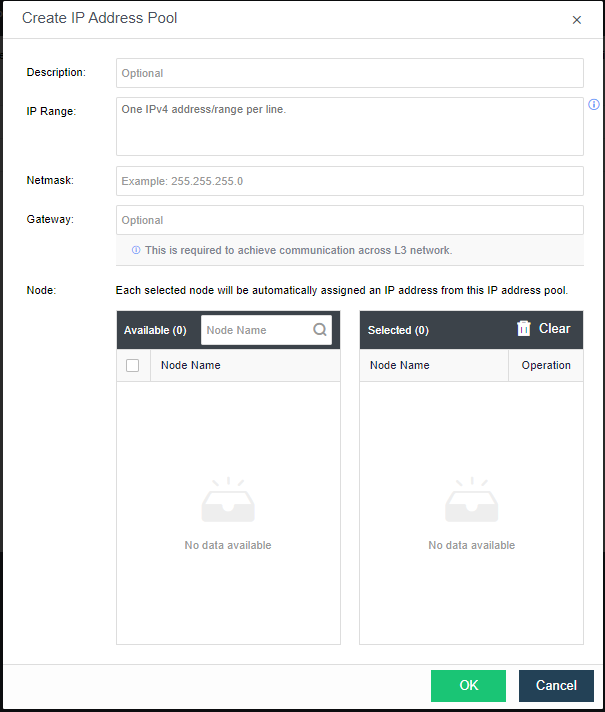
- Click Create to configure the address. Enter the IP pool where the VXLAN IP is located and the netmask. The IP range must be greater than or equal to the number of nodes.
-
Description: Describes the created VXLAN IP pool information.
-
IP Range: The IP address used by the VXLAN node network plane. It supports a single IP setting and range setting and can be set in multiple lines. It is necessary to ensure that all addresses are in the same network segment.
-
Netmask: The mask information of the IP address in the VXLAN IP pool.
-
Gateway: If cross-layer data communication is required, fill in the layer 3 gateway.
-
Node: The node that uses the IP in the VXLAN IP pool.
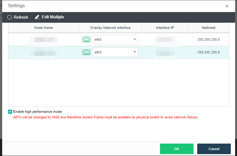
- By checking the Enable high performance mode checkbox, the MTU of the HCI node interface will be set to 1600 bytes so that the data encapsulated by VXLAN will not be fragmented when sent to the physical network. It can significantly improve the forwarding performance of the virtual network. At this time, the opposite physical switch must enable a jumbo frame.
Virtual Storage Configuration
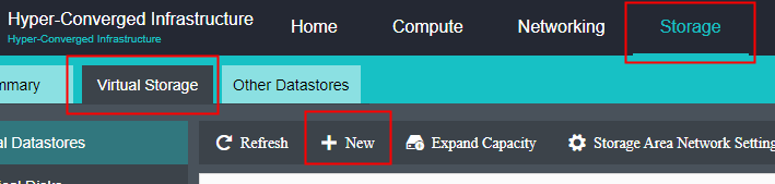
After the HCI node is organized into a cluster, navigate to Storage > Virtual Storage and click New. Because it is the first time to set up virtual storage, the system will automatically prompt to configure the storage private network.
Configure Storage Network Interface
Precautions
-
Upgrade from the lower version to HCI6.7.0, the storage network deployment mode is Link Aggregation with One Switch or Link Aggregation with Two Switches by default.
-
Deploying the new storage network in the standard link aggregation mode is recommended.
-
If the storage area network is configured with standard link aggregation, link aggregation with one switch, and link aggregation with two switches, it is not supported to configure a static route to this network interface. Static routes can be configured in Link aggregation disabled mode.
-
It is forbidden to use Round robin among interfaces for the storage area network interface.
Steps
-
Navigate to Storage under Virtual Storage and click Storage Area Network Settings to configure the storage deployment mode.
By default, eth0 is used as a management interface and communication interface to synchronize configurations on the Sangfor HCI platform. The storage network interface is used to synchronize file data on virtual storage. It is better to use separate interfaces such as the management interface and storage network interface. It is recommended to use Standard Link Aggregation mode to form a storage area network for both standard and stretched clusters.
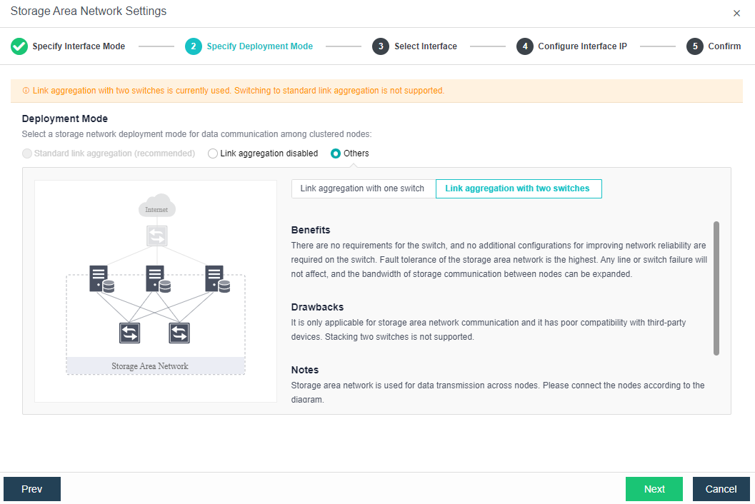
Deployment mode:
a. Standard link aggregation (recommended): By configuring interface aggregation on the node and switch, the node can connect to the third-party storage or third-party server through the virtual storage interface. If two switches are used, the switch must also be configured into stacking mode. Selecting the Layer 4 load balancing as the interface load balance mode is recommended.
b. No link aggregation: The network storing data communication is independent, and there is no requirement for the switch. It can be an ordinary layer 2 switch, and there is no need to make any configuration on the switch. However, when a link fails, the storage on the connected host will be directly unavailable.
c. Others
-
Link Aggregation with One Switch: A single switch is used for storage network link aggregation. There is no requirement for the switch. It can be an ordinary layer 2 switch, and there is no need to make any configuration on the switch. The failure of a single link does not affect storage communication.
-
Link Aggregation with two switches: Two switches are used for storage network link aggregation. There is no requirement for switches. Ordinary layer 2 switches do not need to make any configuration on the switches. They have high fault tolerance. Any line or switch failure will not affect storage communication.
- Each node uses two interfaces for storage communication, and all communication interfaces are connected to the same layer-2 switch. The storage communication network interface between nodes will perform link aggregation by itself (the switch is also required to configure link aggregation). After selecting the storage communication deployment mode, you need to connect according to the schematic diagram of the deployment mode, then select the storage network interface corresponding to each node and configure the communication interface address.
- After the storage network interface IP configuration is complete, the storage private network configuration is complete.
Configuring Datastore Type and Disks
The virtual storage volume is divided into Ordinary datastore and Stretched datastore. When the HCI cluster is planned to be a standard cluster, select Ordinary datastore. When planning an HCI cluster as a stretched cluster, select Stretched datastore.
During virtual storage initialization, there is no need to select the number of replicas. The same virtual datastore can configure two replicas and three replicas.
When the number of cluster nodes is three or four, if you need to use three replicas, each node must have two hard disk groups. There is no hard disk group limit when the number of cluster nodes is five or more.
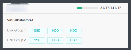
A hard disk group can be a mixed configuration of SSD and HDD or a pure SSD. As shown in the figure above, the node has two Disk Groups.
Create Ordinary Datastore
Precautions
- For large cluster projects, it is recommended to use multiple volumes. It is recommended that the number of nodes per volume be less than 12 and not more than 16 as far as possible. For example, 48 nodes in the cluster are recommended to be divided into four volumes and 12 nodes per volume.
- Using RAID volumes to build virtual storage is not recommended because they generally do not support hot plugs. RAID should be configured as JBOD passthrough. If JBOD is not supported, disable RAID and use non-RAID.
Steps
- Navigate to Storage > Virtual Storage, click New, and select the volume type as Ordinary datastore.
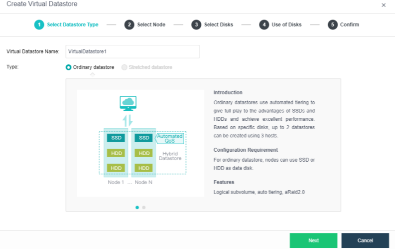
- Select the corresponding method and nodes to create a virtual datastore. Since we are creating the first virtual datastore, choose the Use disks on new hosts.
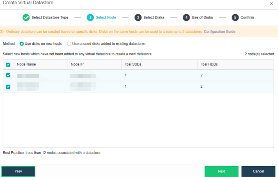
-
Select the hard disk to be added to the node. Configure hard disks and hard disk groups, and then make a detailed usage plan for each node’s disk. The system will automatically detect the disks of all nodes in the cluster. By default, mechanical disks are selected as data disks and solid-state disks as cache disks. Using the default configuration is recommended. If you need to deploy multiple databases, you need to plan to reserve the disks of the second database group.
Select the disks that will be used to create a virtual datastore.
For a hybrid datastore, at least one SSD is required as a cache disk.
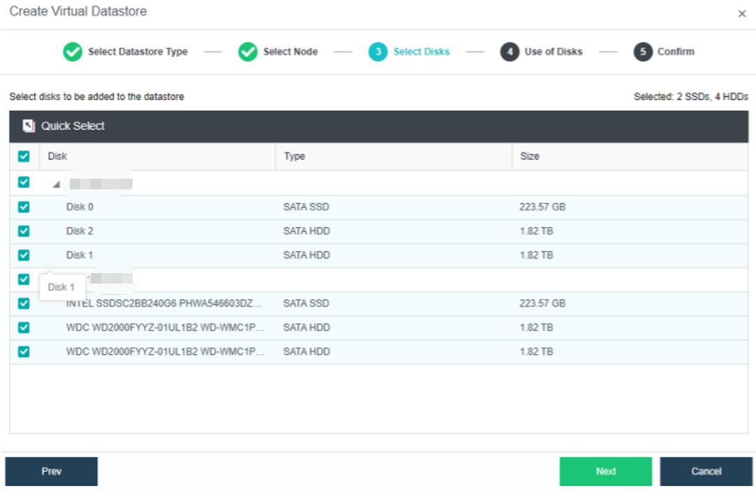
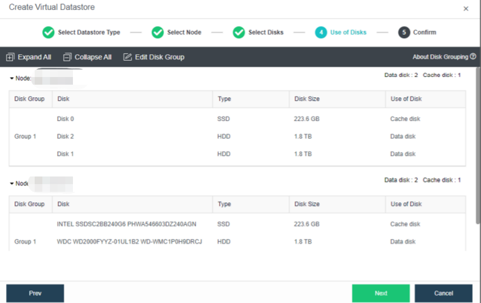
- Confirm the details and proceed.
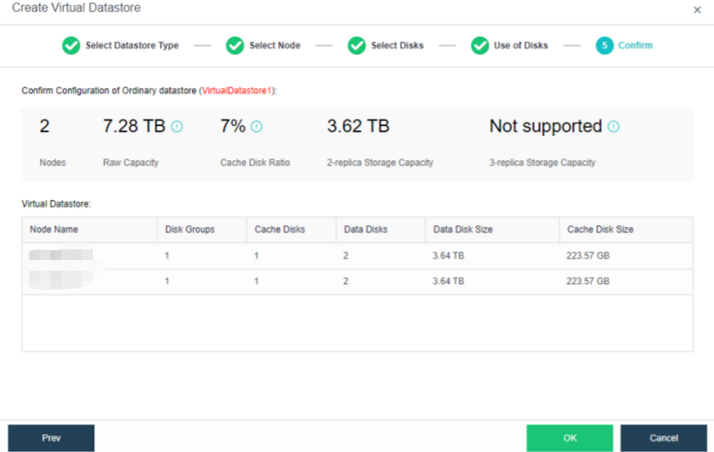
- The following page displays virtual storage configurations, including available disk space, number of data copies, and the total number of disks. After confirming configurations, click OK. Then, input the administrator account password: admin. Then, click Finish to begin initializing virtual storage.
Create Stretched Datastore
Steps
- Configure the storage datastore type. Navigate to Storage > Virtual Storage and click New. Then, select the datastore type as Stretched datastore.
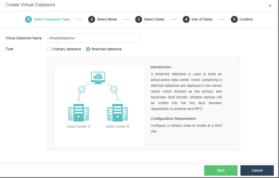
- Select the node. Select the nodes to be added to the stretched datastore. The stretched cluster requires at least 4 nodes.
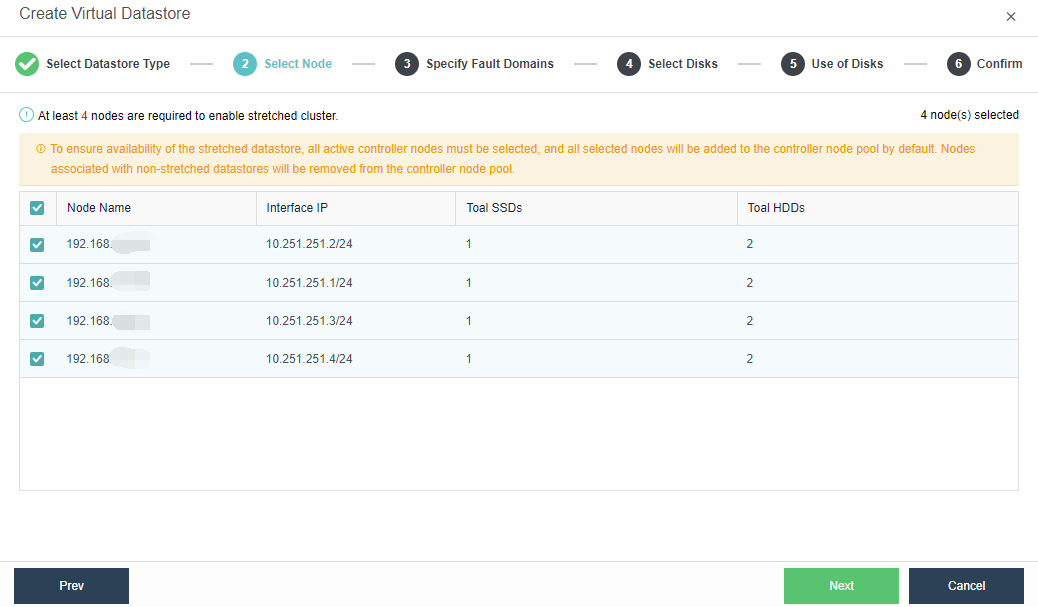
- Specify fault domains. Add the required nodes to the corresponding fault domains. There are four nodes in this example, so two nodes are added to the Primary Fault Domain, while another two are added to the Secondary Fault Domain.
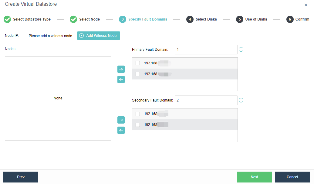
- Add Witness Node: Configure the witness node IP according to the pre-installed witness node after naming the Primary Fault Domain and the Secondary Fault Domain. Follow the wizard to enter the password to confirm the configuration of the witness node.
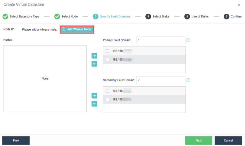
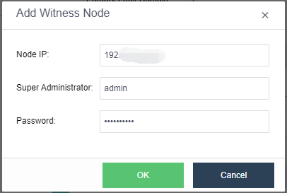
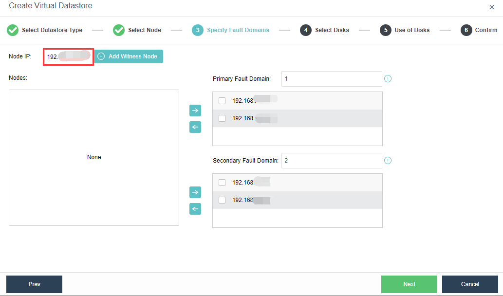
Note:
After logging in to the witness node, you need to enable the SSH Port of the witness node under System > Port Management.
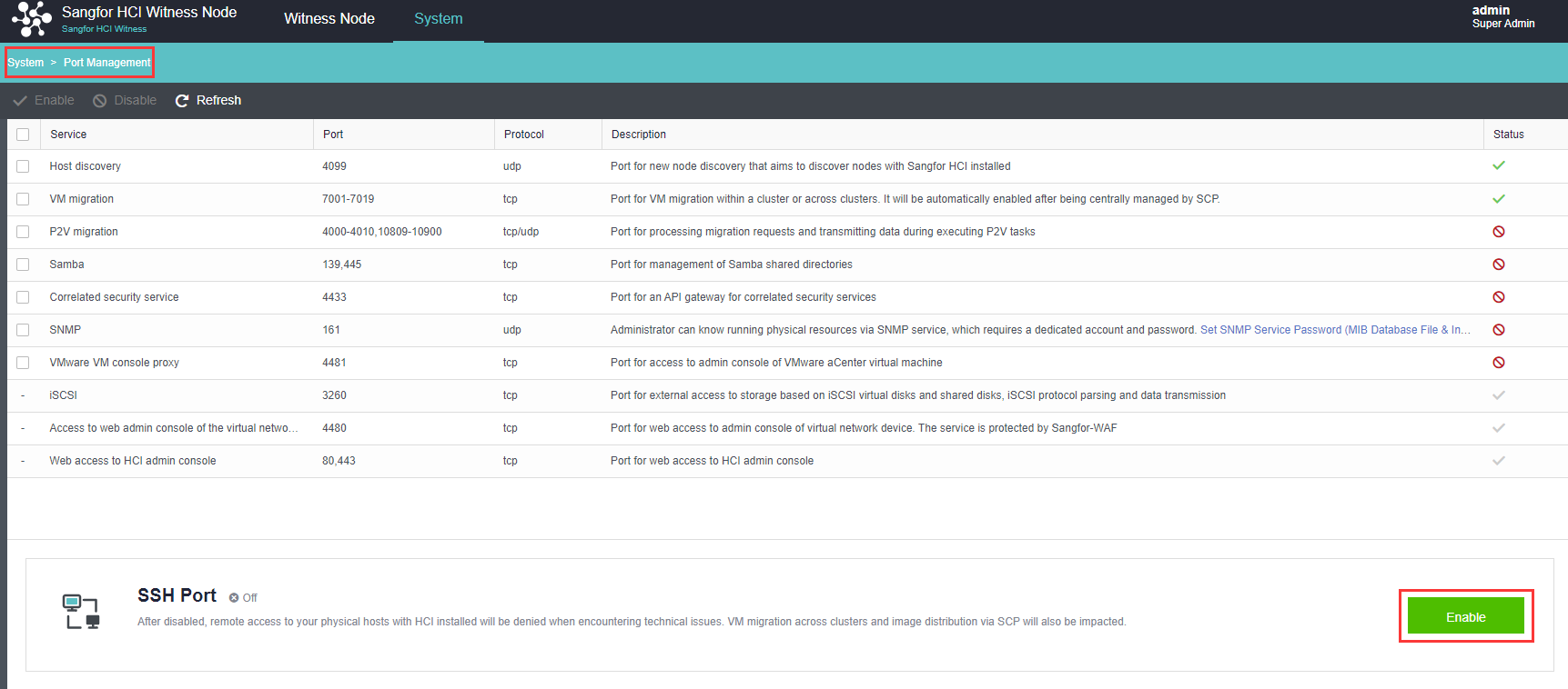
- Confirm the configuration: Confirm the configuration of the fault domain. Modifying the fault domain where the node is located after the datastore is created is not supported.
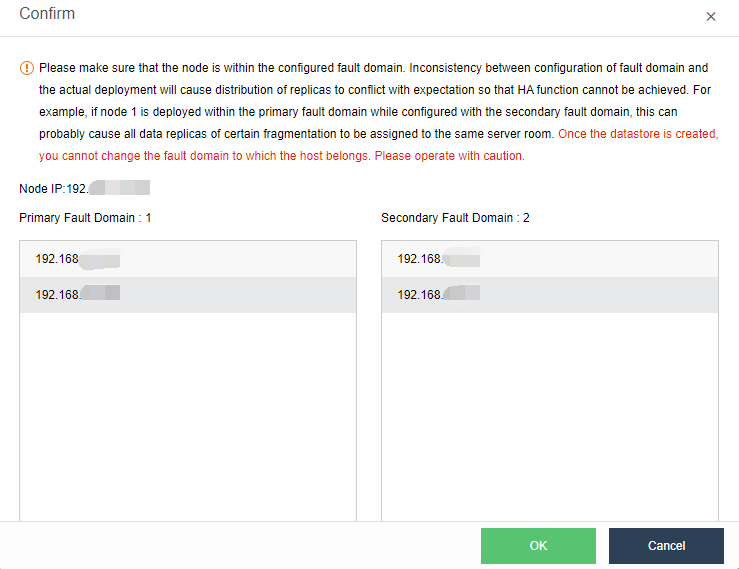
- Configure the Use of Disks. Next, you need to plan the use of disks, including data disk, cache disk, and spare disk. Generally, SSD is used as a cache disk to improve the IO performance of virtual storage. The system automatically recommends the type of hard disk according to the configuration. You can follow the default recommendations of the system.
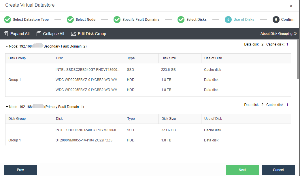
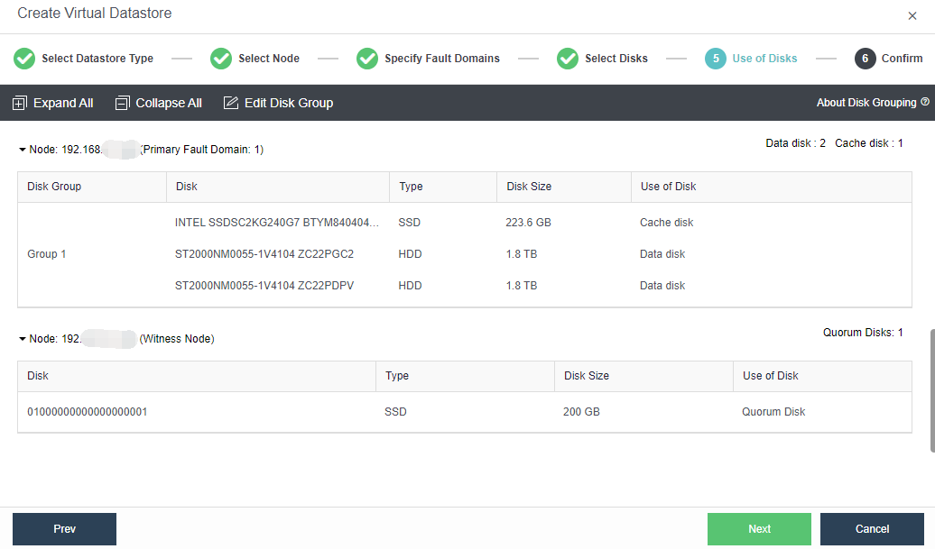
- Confirm the configuration. Finally, the page displays the configuration result information of the virtual datastore, including the final storage capacity, the number of copies, and the number of disks. After confirming that the configuration is correct, you need to enter the administrator password and click OK to start initializing the virtual datastore.
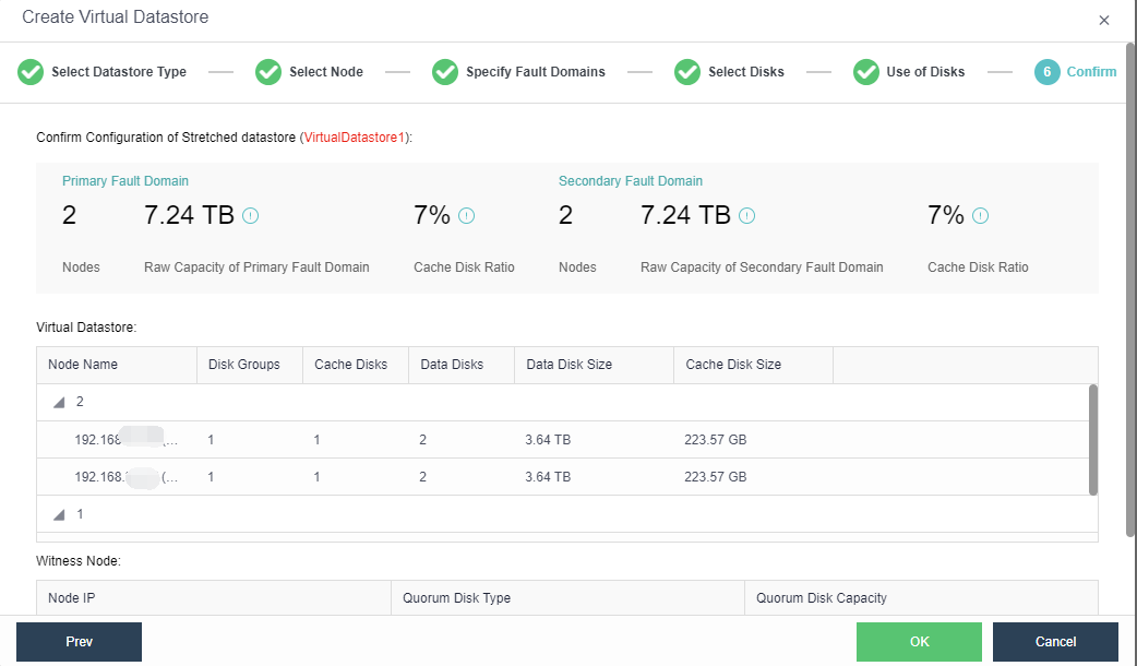
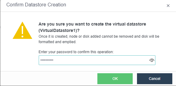
aDesk Communication Interface (Optional)
Description
Applicable to VDI scenarios, the platform supports scaling endpoint communication interfaces for aDesk/VDI services separately for the communication between aDesk/VDI clients and servers.
Precautions
- It is recommended to prioritize using the idle physical network interface of HCI and configure a static route on the HCI platform so that the IP on the endpoint communication interface can communicate with the network where the user endpoint is located (direct connection mode) or the AD device serving as a proxy gateway (AD proxy mode).
- In the scenario where the HCI cluster only runs VDI services, in consideration of simplified deployment, the aDesk communication interface and the management interface can be multiplexed. In this case, the configuration of the management interface should be at least dual Gigabit link aggregation mode.
- The end user’s internal network security device needs to allow the traffic for aDesk network and proxy devices (such as AD proxy gateway, aTrust proxy gateway) to access the aDesk and node communication interface TCP&UDP 5500, 8888, 13500-13999 communication permissions.
- It is forbidden to use Round robin among interfaces for aDesk communication interface.
Topology
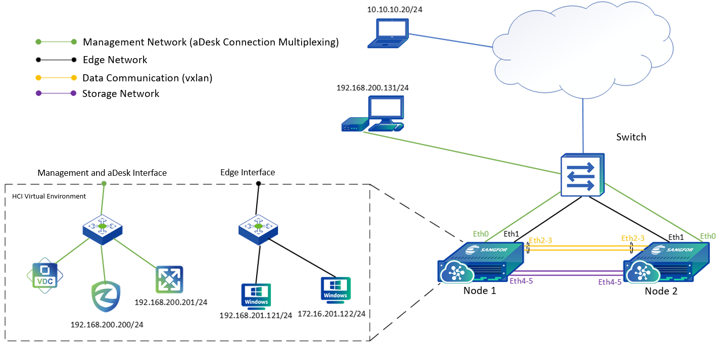
Steps
- It is recommended to use aggregated network interface: in the HCI WebUI console, navigate to Nodes > Physical Interfaces then click Add multiple aggregate interfaces, and select two network interfaces. For example, eth2 and eth3, and the load balancing mode of aggregate interface support selecting Static Aggregation and LACP mode. If it is standard link aggregation, it is recommended to select the Layer 4 load balancing mode. If the switch does not support the Layer 4 load balancing, then it is recommended to select the load balancing mode Based on MAC address.
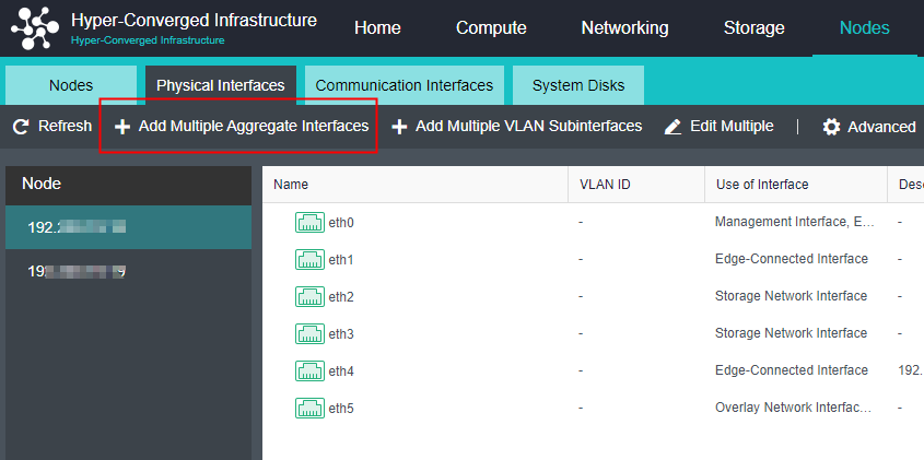
- In the HCI WebUI console, navigate to Nodes > Communication Interfaces, click the aDesk Communication Interface, and click Settings to enter the configuration page, where you can modify the aDesk Communication Interface.
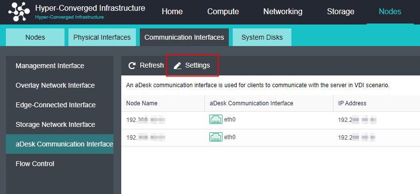
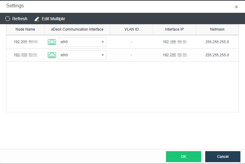
License Activation
USB KEY Licensing
Steps
- Connect the license/USB key to the cluster controller node, navigate to System and click Licensing Management to enter the licensing page.
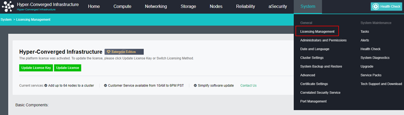
- Click Update License to enter the Activate License page to import the license key file.
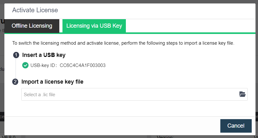
- After importing, you may view the licensing details.
Virtual Key Licensing
Description
Sangfor HCI supports key-free licensing, which uses the virtual key for licensing and prevents hardware/USB key loss or failures that affect the HCI cluster usage. There is no need to return and re-apply for the USB key in the license change or update scenario, improving the efficiency.
Precautions
- Only HCI 6.8.0 and above support virtual key licensing.
- USB key and virtual key licensing cannot coexist at the same time.
- For HCI 6.8.0 and earlier version, the USB key licensing method is used by default, and the licensing method can be switched after the version upgrade. Please contact Sangfor technical support for further assistance.
- After switching the licensing method, the original USB key will be invalid.
- Virtual key licensing currently only supports Offline Licensing, and online authorization is not supported.
- For virtual key licensing, it is required to export device info for two nodes. If one of the nodes is replaced, the license will become invalid. You need to contact Sangfor technical support for further assistance.
- If the license key file is not imported after the cluster is created, it is not allowed to create a new virtual machine. Only SCP virtual machines can be imported.
Steps
- Navigate to System > Licensing Management, then click Update License to enter the Offline Licensing page.
- Select the nodes and export the device information.
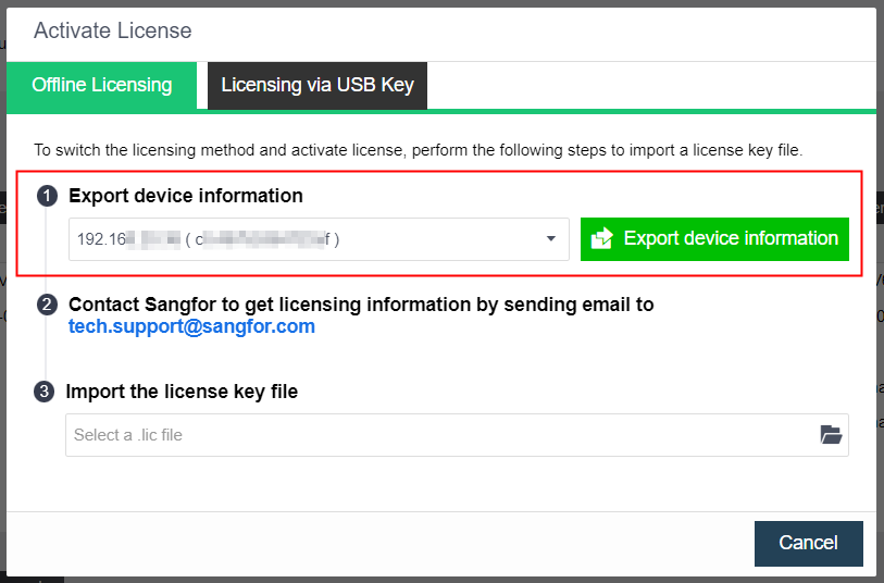
- Contact Sangfor and provide the device information file(.info) to get the license file.
- Import the license file to complete the licensing.
Configure Link Layer Discovery Protocol (LLDP)
Description
Sangfor HCI supports the LLDP protocol to the connected switch interface. It enables the network interface number, MTU, TTL, and other information of the peer devices directly connected to the interface can be obtained, which is effective for administrators to operate, maintain and locate faults in the switch.
Precautions
- It only supports viewing LLDP information on a single physical network interface but does not support viewing LLDP information on aggregated interfaces and VLAN subnet interfaces.
- If there are multiple VLANs on the trunk interface of the switch, only one VLAN can be displayed.
- Some other brands’ switches will forward LLDP packets of other devices (e.g., Sundray switches), resulting in the obtained LLDP information that is not the information of the directly connected interface on the switch end.
Prerequisites
The connected switch has enabled the LLDP protocol.
Steps
- Navigate to Nodes > Physical Interfaces, select a node, and click Advanced > Configure LLDP.
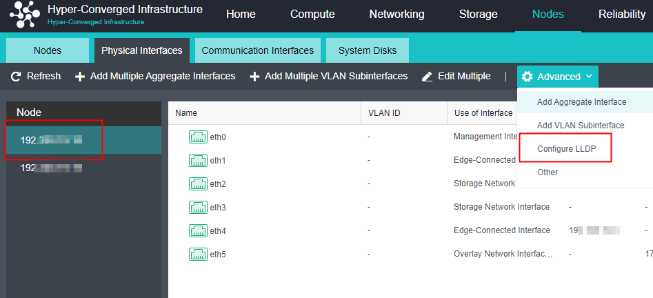
- Select the network interface to obtain the peer device information and click the Enable button.
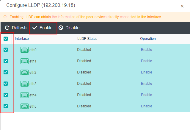
- After LLDP is enabled, go back to the Physical interfaces, locate the corresponding physical network interface, and click the View LLDP button. Then, you can view the LLDP information transmitted by the network interface of the peer devices/switches.
- Device ID: The MAC address of peer devices/switches.
- Port ID: The port ID of peer devices/switches.
- TTL: Time to live, packet’s lifetime.
- Port Description: Custom description.
- OS Name: Name of the peer devices/switches.
- OS Feature: Mode of the peer devices/switches.
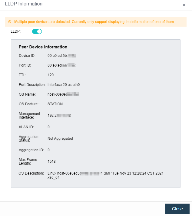
Physical Edge Configuration
A virtual machine may run on any node if multiple nodes form a cluster and provide business service. Therefore, an edge should be connected to an interface on each node. Furthermore, that interface should be connected to the same Level 2 physical switch, ensuring that virtual network traffic can go into the physical network through any node.
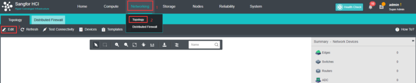
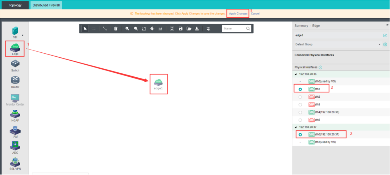
Three Networks Multiplexing (Optional)
Description
When the physical NIC of the server is insufficient, the three network multiplexing can be adopted. The three network multiplexing is a network planning scheme in which the management network, physical edge network, and overlay network Interface reuse one aggregation interface.
Precautions
-
The aggregation interface is added to the active/standby mode, and the aggregation peer switch in the active/standby mode does not need to configure aggregation.
-
The active/standby mode only supports the aggregation of two network interfaces.
-
The current aggregation mode does not support the direct aggregation of two existing role network interfaces. You need to move the role to an idle network interface before aggregation.
-
The service interface does not support configuring VLAN sub-interfaces. The service VLAN can only be configured through the interface group of the virtual network.
-
It is recommended to set the upper traffic limit in the case of management, VXLAN, and service triple network multiplexing to ensure the stability of network traffic. When the management communication interface is not multiplexed, the upper traffic limit does not need to be configured. After the speed limit is enabled, you can view the flow of the management interface, VXLAN interface, and service interface in throughput trend on the node details page of Nodes.
-
It is only recommended to deploy in an environment with four 10 Gigabit interfaces.
-
After the active upgrade from the old version, the functional operation will fail if the aggregation interface already exists in the original environment, but it will not affect normal use. The operation can be supported after the node is restarted.
Prerequisites
The multiplex interface of three networks in one must be a 10 Gigabit interface.
Steps
- Click Nodes > Physical Interfaces on the console.

- Because it does not support the direct aggregation of two existing role network interfaces, you must first reuse the Overlay Network Interface to the management communication interface and click Communicate Interface > Overlay Network Interface > Edit Configuration to modify eth1 to eth0.
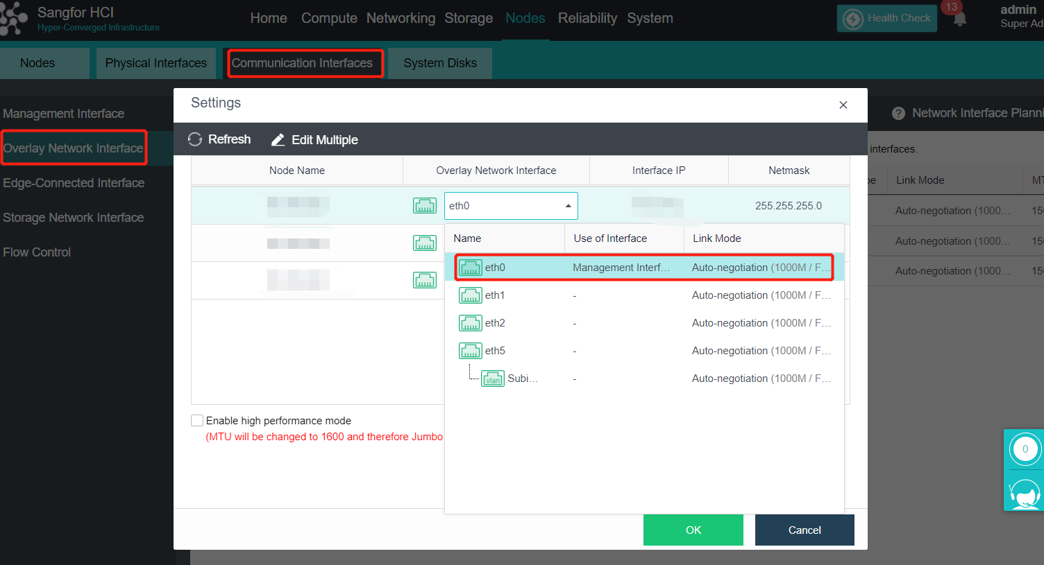
- Aggregate eth0 and eth1, click Add Multiple aggregation Interfaces and select eth0 and eth1. The aggregation mode is recommended to load according to MAC or IP address.
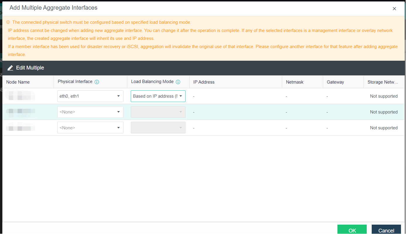
- After aggregation, use the VLAN sub interface to isolate VLANs from different network planes. Click Add Multiple VLAN Subinterfaces, and fill in the corresponding VLAN. The IP address information does not need to be filled in.
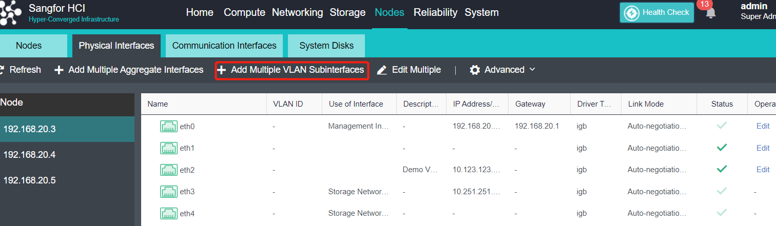
- After the VLAN subinterfaces configuration is complete, switch the management communication interface and Overlay Network Interface to the corresponding subinterface. Navigate to Nodes > Communication Interfaces > Management Interface to configure the management interface, and click Overlay Network Interface to configure the data communication interface.
- Click Virtual Network > Edge to modify the Edge as an aggregation port.
- The configuration is completed.
- It is recommended to set the upper limit of traffic when the management, VXLAN, and service networks are multiplexed to ensure the stability of network traffic.
Four Networks Multiplexing (Optional)
Description
When the physical NIC of the server is insufficient, the four networks multiplexing can be adopted. The four network multiplexing is a network planning scheme in which the management network, physical edge network, overlay network, and storage network interface reuse one aggregation interface. The scheme provides NIC-level redundancy protection, and the failure of a single NIC will not affect the service.
Precautions
-
A single interface does not support the integration of four networks. It can support the aggregation of four physical interfaces for integrating four networks at most.
-
The server NIC aggregation supports the active/standby mode (default) and five load balancing modes according to IP, MAC address, interface polling, and four-layer information. Using the IP mode for load balancing is recommended, and the active/standby mode is not recommended. The access layer switch interface needs to be configured with the corresponding interface aggregation mode. The aggregation peer switch in the active-standby mode can be configured without aggregation.
-
The current aggregation mode does not support the direct aggregation of two existing role network interfaces. You need to move the role to an idle network interface before aggregation.
-
It is recommended to set the upper limit of traffic when the four networks of management, VXLAN, service, and storage are integrated to ensure the stability of network traffic. After the speed limit is enabled, you can view the throughput of the management interface, VXLAN interface, Edge interface, and storage interface on the Nodes > Summary page.
-
At present, only Mellanox CX4 and Intel X710 NIC support the interface multiplexing function for storage interface.
-
It is recommended to configure VLAN for network isolation in each network plane. VLAN sub-interfaces are configured for management, VXLAN, and storage. VLAN sub interfaces are not supported for service interfaces. Service VLAN can only be configured through the interface group of the virtual network.
-
After the active upgrade from the old version, the functional operation will fail if the aggregation interface already exists in the original environment, but it will not affect normal use. The operation can be supported after the node is restarted.
-
The device upgraded from the old version enables the integration of four networks. The Intel network card will interrupt the network for 30 seconds (restart DP + switch STP convergence). The Mellanox NIC needs to restart the physical node before it takes effect.
-
The motherboard must support VT-D (supported by all CPUs after the third generation). The new delivery aServer will turn on when installing the system. If the vt-D function is not enabled before upgrading the old version or the third-party device, it needs to be restarted to take effect.
Prerequisites
- The multiplex interface of interface sharing must be at least two 10 Gigabit interfaces.
- VLAN is recommended to be configured for network isolation in each network plane, so the switch interface connecting the HCI host must be configured as a trunk in advance. And configure the planned VLAN in the relevant switch.
Steps
- Click Nodes > Physical Interfaces on the console.
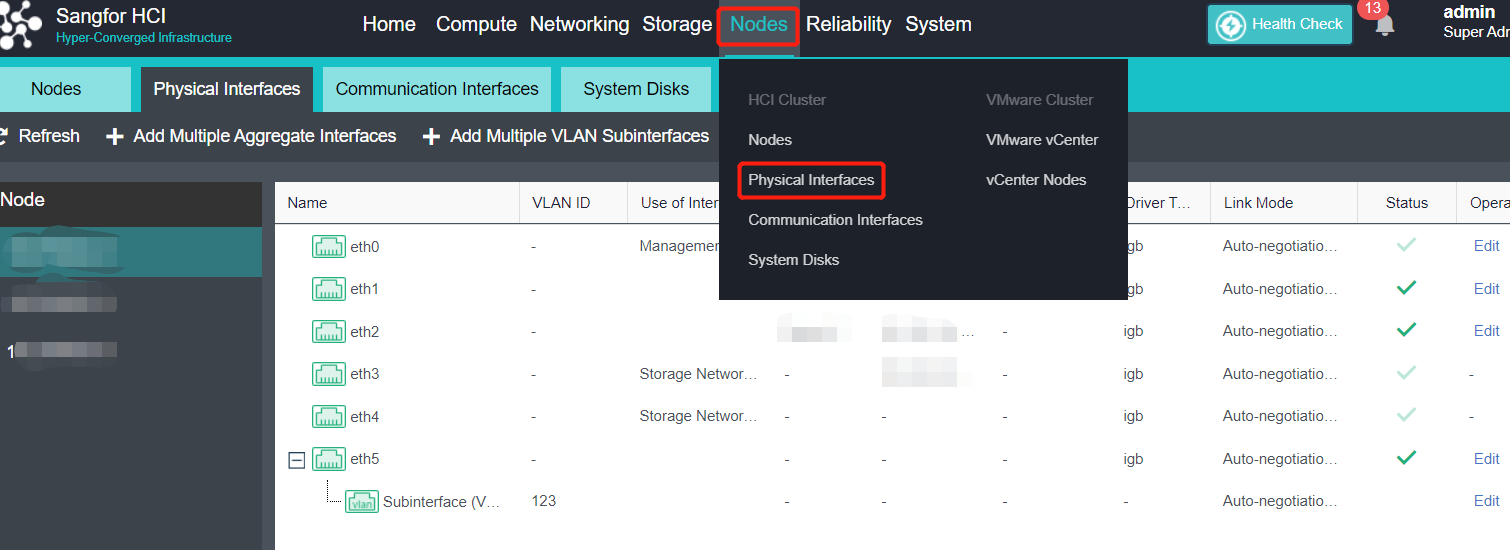
- Since it does not support the direct aggregation of two existing role interfaces, you must first multiplex the Overlay Network Interface to the management interface. Then, Navigate to Communication Interfaces > Overlay Network Interface > Settings to multiplex the Overlay Network Interface to the management interface.

- Select OK.
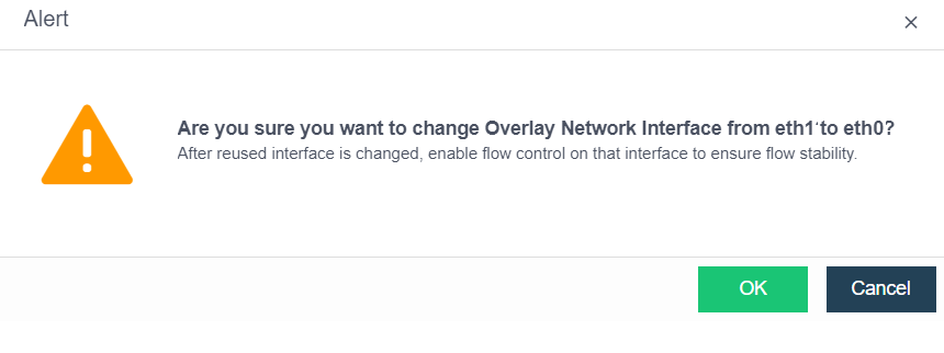
- After all node interfaces are adjusted, click OK. Check the Enable high performance mode checkbox (this operation will set the MTU of the network port to 1600. You need to enable jumbo frame support on the physical switch. Otherwise, the network will be blocked).
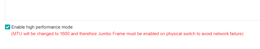
- The Overlay Network Interface has been adjusted to the management interface. The original Overlay Network Interface has no role and can be aggregated.
- Aggregate the planned network interfaces, and enable the storage reuse function when creating the aggregation interface. Aggregation mode is recommended to load according to MAC or IP address.
- Click Add Multiple Aggregate Interfaces, and select the planned interface. Next, select the aggregation network interface working mode. The active-standby mode is not recommended, and the network interface utilization is poor (after configuring the non-active-standby aggregation mode, you need to adjust the aggregation mode of the connected switch to match the platform. Otherwise, you will not be able to access the platform). Check the Storage Network Interface Multiplexing checkbox, and click OK.
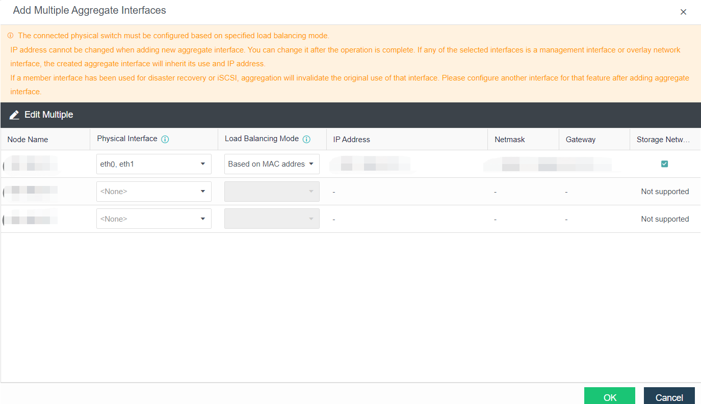
- Confirm to enable Storage Communication Interface Multiplexing. Before enabling the Storage Communication Interface Multiplexing function, you need to restart the network service, temporarily interrupting the physical node and the VM networks running on that specific node for several minutes. Please operate with caution.
- Click OK to bulk add the aggregation interface of the node. Please ensure that the IP address and VLAN ID are configured correctly to avoid network interruption after the configuration takes effect.
- As shown in the figure below, click Reset Storage Area Network, and adjust the storage communication interface.
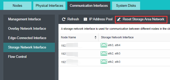
- Select Shared Mode. Click Next, select the aggregation interface with the previously enabled Enable storage network interface sharing. Fill in the planned VLAN ID and interface IP address, and click OK.
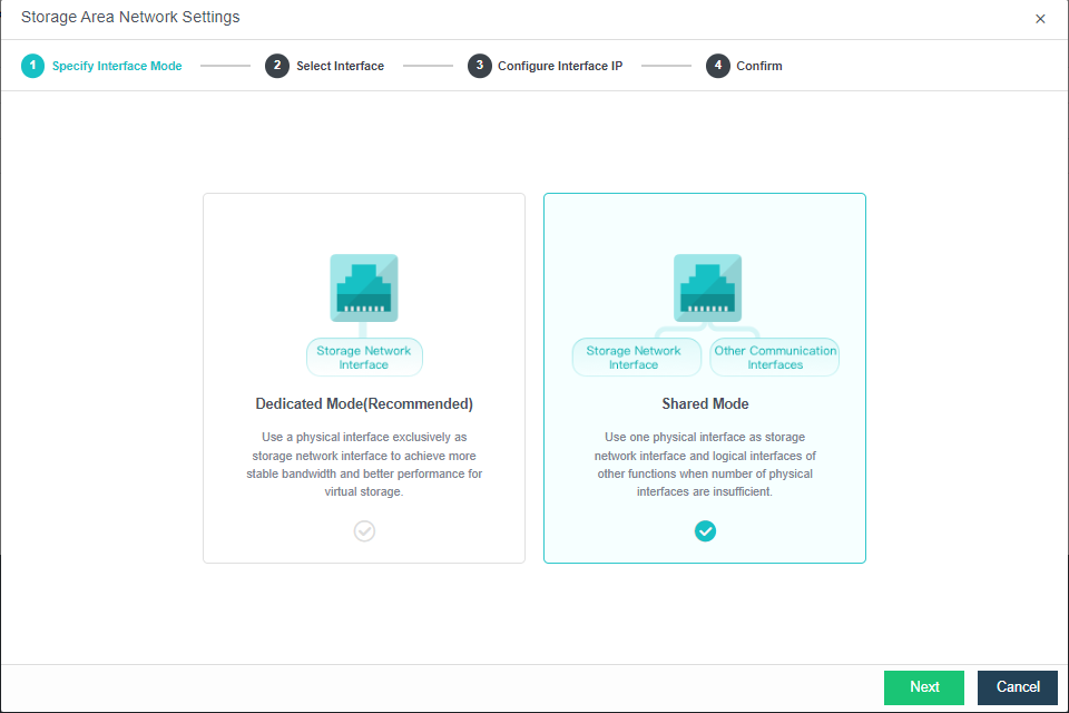
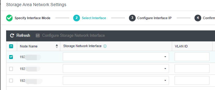
- Click Edit Configuration and adjust the Overlay Network Interface interface.
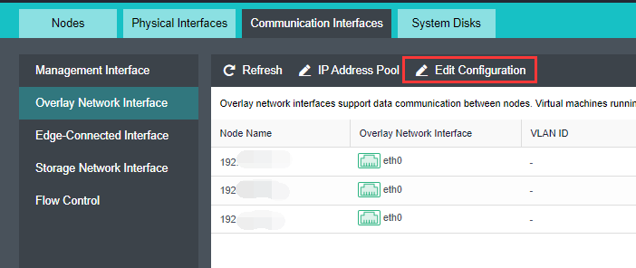
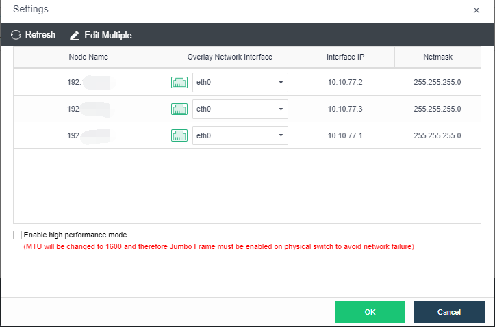
- Click IP Address Pool.
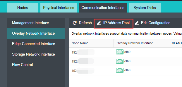
- Click Create for the new pool and fill in the planned IP address/netmask.
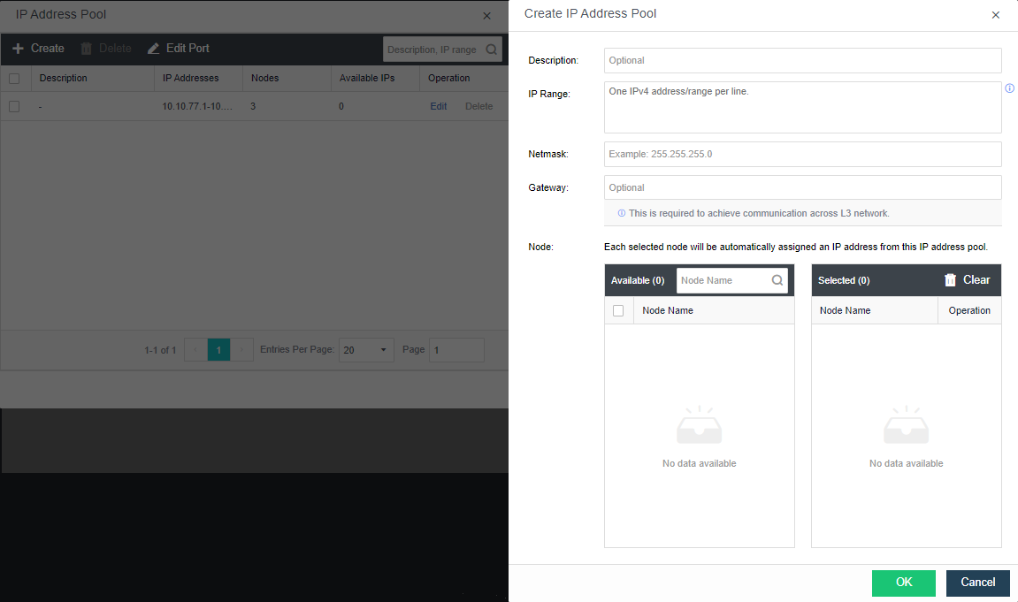
- Under Physical Interfaces, select Add Multiple VLAN Subinterfaces.
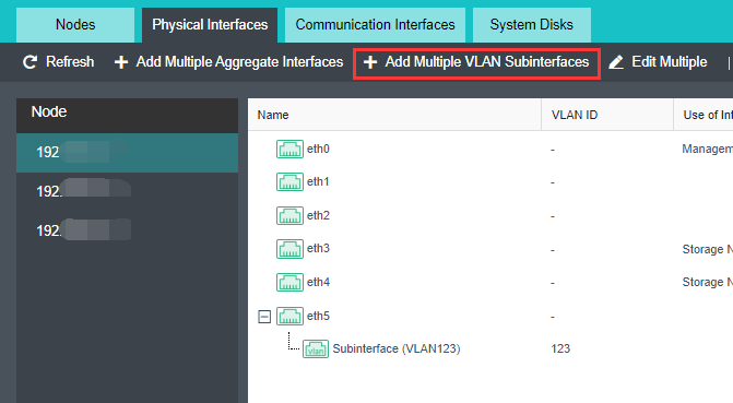
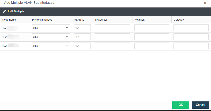
- Change the overlay network interface to the newly created VLAN subinterface. It will cause a short network interruption.
- Navigate to Nodes > Communication Interfaces > Edge-Connected Interface. Then, click Add New Edge, select the available network interface for all nodes and click OK to create the Edge.
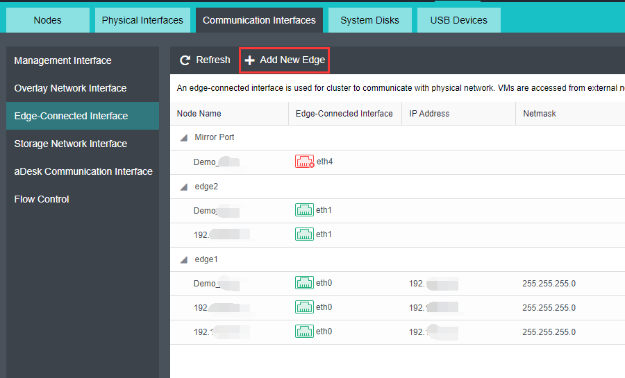
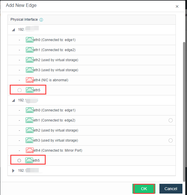
- Select the Edge and click Connect To Node.

- Click New to select the network interface and node.
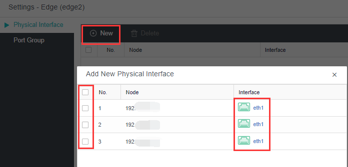
- The configuration for the physical edge network interface is done. The physical edge interface does not support configuring VLAN sub-interfaces. The edge interface VLAN can only be configured through the interface group of the virtual network.
- Select the sub-interface of the management network interface and configure the planned VLAN ID for it.
- All interfaces of interface sharing have been configured.
- It is recommended to set the upper limit of bandwidth/traffic in the case of management, VXLAN, service, and storage interface multiplexing to ensure the stability of network traffic. When creating a cluster, it is recommended to configure 3Gbps for the management interface. The service interface and VXLAN are configured with 5Gbps. The storage interface is configured with 8gbps. Subsequently, the traffic of each network plane is observed and then optimized and adjusted.
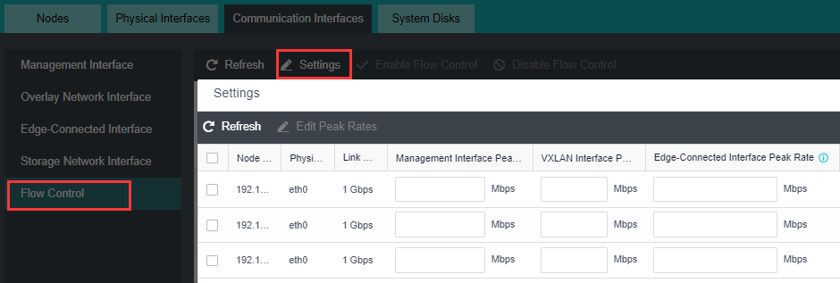
Health Check of Cluster Status
After the platform is deployed, you need to check whether the configurations in the cluster are correct. Click Health Check on the home page. Select the items that need to be detected, and click Start. Confirm that the final score of the test is 100. If the score is lower than 100, it shall be handled according to the suggestions of the test results or contact Sangfor technical support.
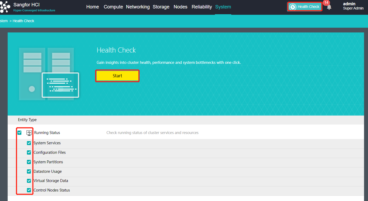
Use the aDeploy Tool For Detection
After the platform is deployed, you need to check whether there are patches available in the current version that need to be upgraded. Please use aDeploy tool to check and upgrade the corresponding patch package according to the test results.
aDeploy tool download address:
http://adeploy.sangfor.com:8080/download/aDeploy-server-install.zip
Sangfor aSecurity (aSEC) Deployment
Sangfor HCI supports the aSecurity deployment by importing virtual machines. This chapter mainly introduces the installation and deployment of the aSecurity, including the installation of the aSEC virtual machine and the deployment of the security protection management(ES/EDR) platform.
- The deployment flow of aSecurity is shown below.
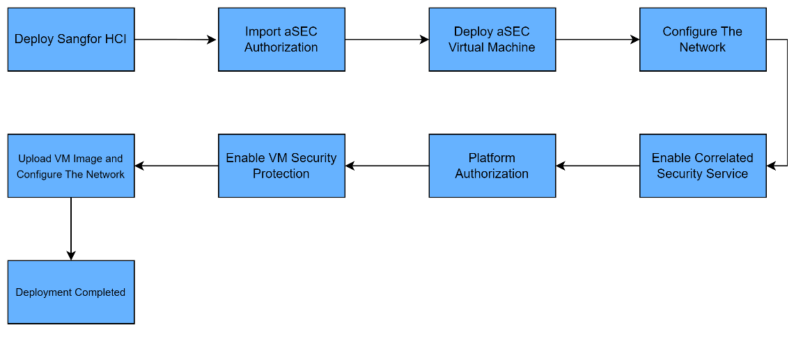
- The network topology plan for Sangfor aSecurity deployment is shown in the figure below. The Sangfor aSecurity platform needs to be able to communicate with the HCI management network (it is recommended to be on the same network segment as the HCI management network). It is mainly used by Sangor aSecurity to call the API interface of HCI to execute tasks such as taking snapshots or creating distributed firewall policies.
- The management interface of the security protection virtual machine will be connected to the physical interface (the physical interface must bridge to the HCI management interface, and it is recommended to be on the same network segment as the HCI management network).
- The edge interface (optional) of the security protection virtual machine is connected to the physical edge interface to connect to the security servers, such as virus databases and cloud search services for automation of virus databases update.
Note:
The quarantined VMs will be added to the aSecurity quarantine policy. The policy will not take effect if the VM is directly connected to the edge.
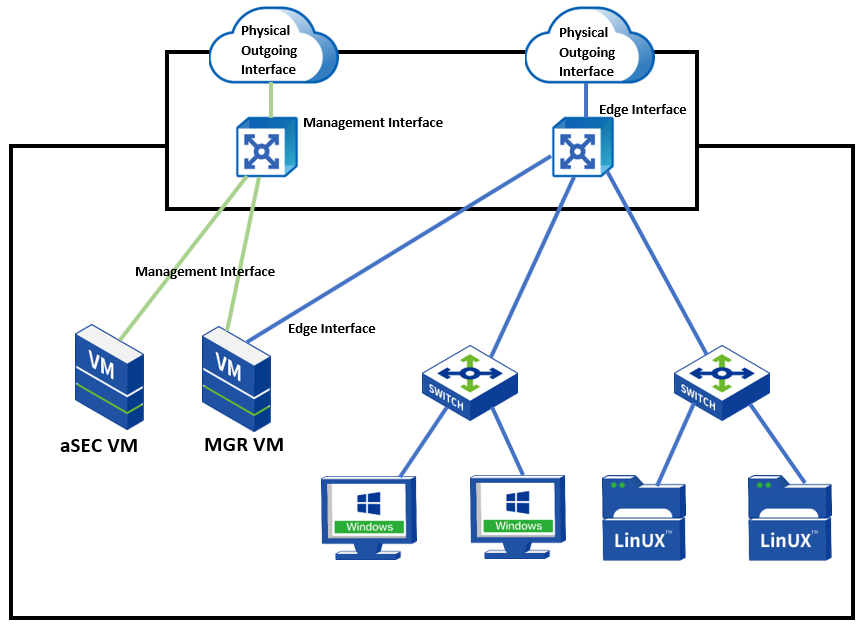
- Sangfor aSecurity deployment recommended specification.
| aSEC Virtual Machine Recommended Specification | aSEC Virtual Machine Recommended Specification | aSEC Virtual Machine Recommended Specification | aSEC Virtual Machine Recommended Specification |
|---|---|---|---|
| Number of Endpoints | CPU | RAM | Disk |
| 1 – 300 (default specification) | 4 Cores | 8G | 300G |
| 300 – 1000 | 4 Cores | 16G | 300G |
| 1000 – 2000 | 8 Cores | 32G | 300G |
| Security Protection Virtual Machine Recommended Specification | Security Protection Virtual Machine Recommended Specification | Security Protection Virtual Machine Recommended Specification | Security Protection Virtual Machine Recommended Specification |
| Number of Endpoints | CPU | RAM | Disk |
| 1 – 300 (default specification) | 2 Cores | 2G | 300G |
| 300 – 1000 | 2 Cores | 4G | 300G |
| 1000 – 2000 | 4 Cores | 8G | 300G |
aSEC Deployment
Precautions
- Only support deploying Sangfor aSecurity on Sangfor HCI 6.8.0 version currently.
- Have aSecurity (aSEC) licensed.
- You must change the Security (aSEC) password once every three months.
Steps
- In the Compute page, click New, select Import VM, navigate to aSecurity, and click Deploy Now to import the virtual machine file.
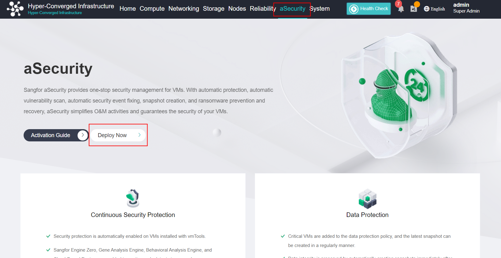
- Import the virtual machine vma file, select the Group, Datastore, Storage Policy, and Run Location, then import the virtual machine.
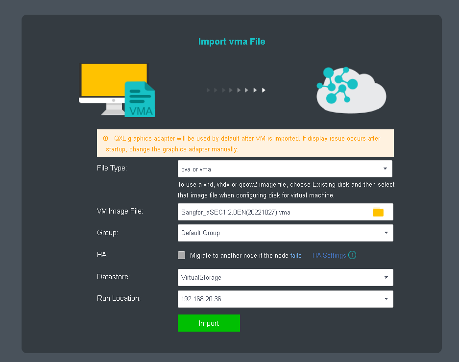
- After successfully importing the virtual machine, Edit the virtual machine to configure the network interface. Check the Enable checkbox on Connect to edge interface, then Enable IPv4 Address to edit the IP Address, Netmask, and Gateway for aSEC virtual machine as its management network. (It is required to ensure the communication between the HCI management interface is reachable, and it is recommended to be on the same network segment as the HCI management interface).
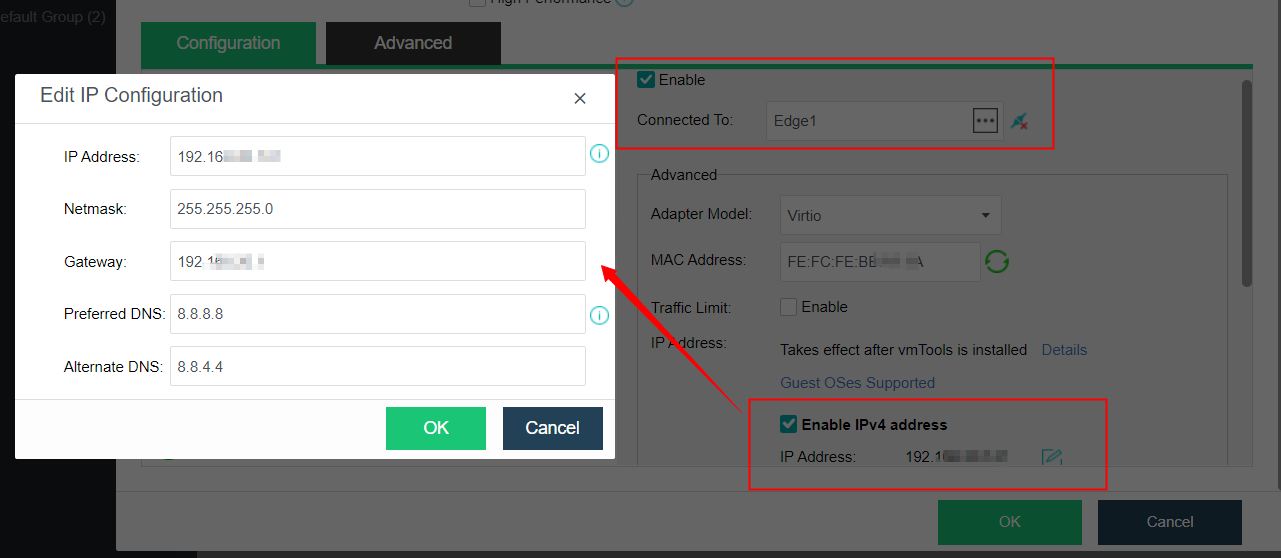
- Navigate to System > Port Management to enable the Correlated Security Service. Otherwise, it is unable to visit the aSecurity platform.
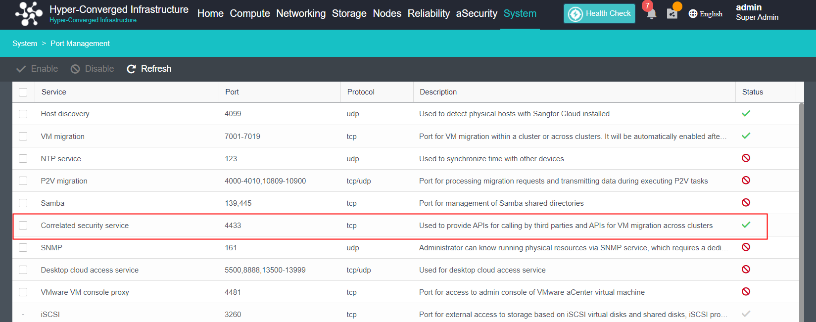
- Power on the aSEC virtual machine and enter into the console to configure the platform correlation.
Step 1. Input the password of Sangfor aSecurity to login. It is required to change the password for first-time login. The default password is Sfcsec@123. The password policy is as follows:
- Password length should be 8 to 64 characters.
- It must contain uppercase letters, lowercase letters, numbers, and special characters such as ~`@#%&<>"’,;_-^$.*+?=!:|{}()[]/ .
- It cannot be the same as or contain the username.
- The same character cannot appear consecutively, such as aaa, 11, etc.
- Cannot use the common characters (including uppercase and lowercase) of sangfor/sinfor/dlanrecover.
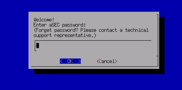
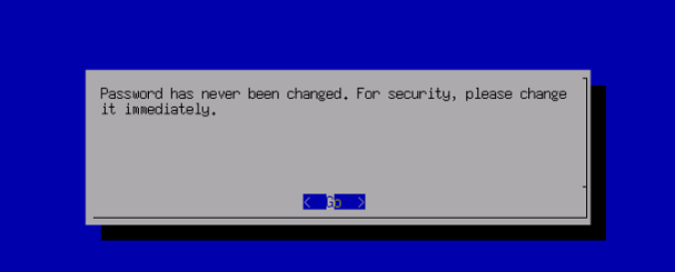
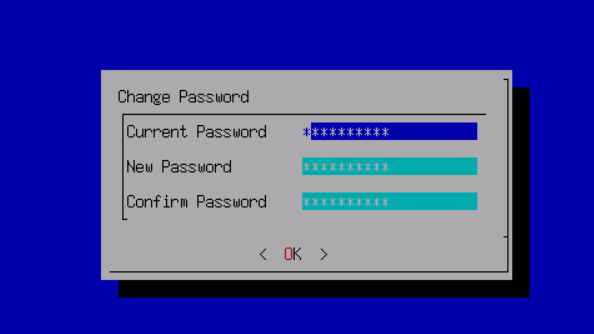

Note:
If there is no password change within 10 minutes or the password change fails, it will prompt an internal error, and the session will be timed out. You need to log in again to change the password.
Step 2. After successfully logging in, select Platform Authentication to enter the HCI platform authentication page.
- Cluster IP: HCI cluster IP.
- Username/password: HCI super admin login credentials.
Step 3. Click Authenticate to complete the aSEC virtual machine deployment.
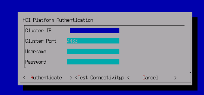

VM Security Protection Deployment
Prerequisites
The aSEC deployment has been completed.
Steps
- After the aSEC has been deployed, go to the aSecurity page. An alert will prompt, then click Go Now to enable VM security protection.
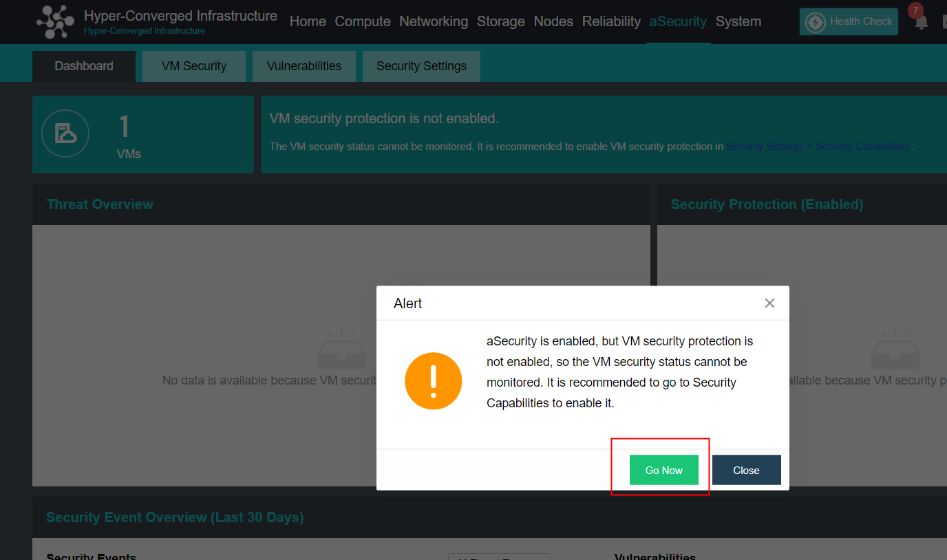
- In the Security Settings > Security Capabilities page, click the Enable button for VM security protection to enable VM security protection.
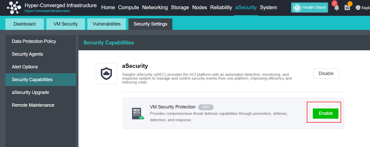
- Configure and deploy the ES manager management platform.
-
Basics
Import VM image file.
Select the datastore.
Select the run location.
-
Management Interface: The interface connects to the HCI cluster management network. The management interface IP address must be in the same network segment as the management network. It is recommended to make overall network planning first.
-
Edge-Connected Interface: The interface connects to the antivirus database, cloud-based engine server, etc. It is recommended to make overall network planning first. Please make sure the interface can connect to the following servers: (refer to the knowledgebase for details)
a. Antivirus Database
b. Vulnerability Signature Database
c. Neural-X
d. Cloud-Based Engine Server
e. Cloud Security Program
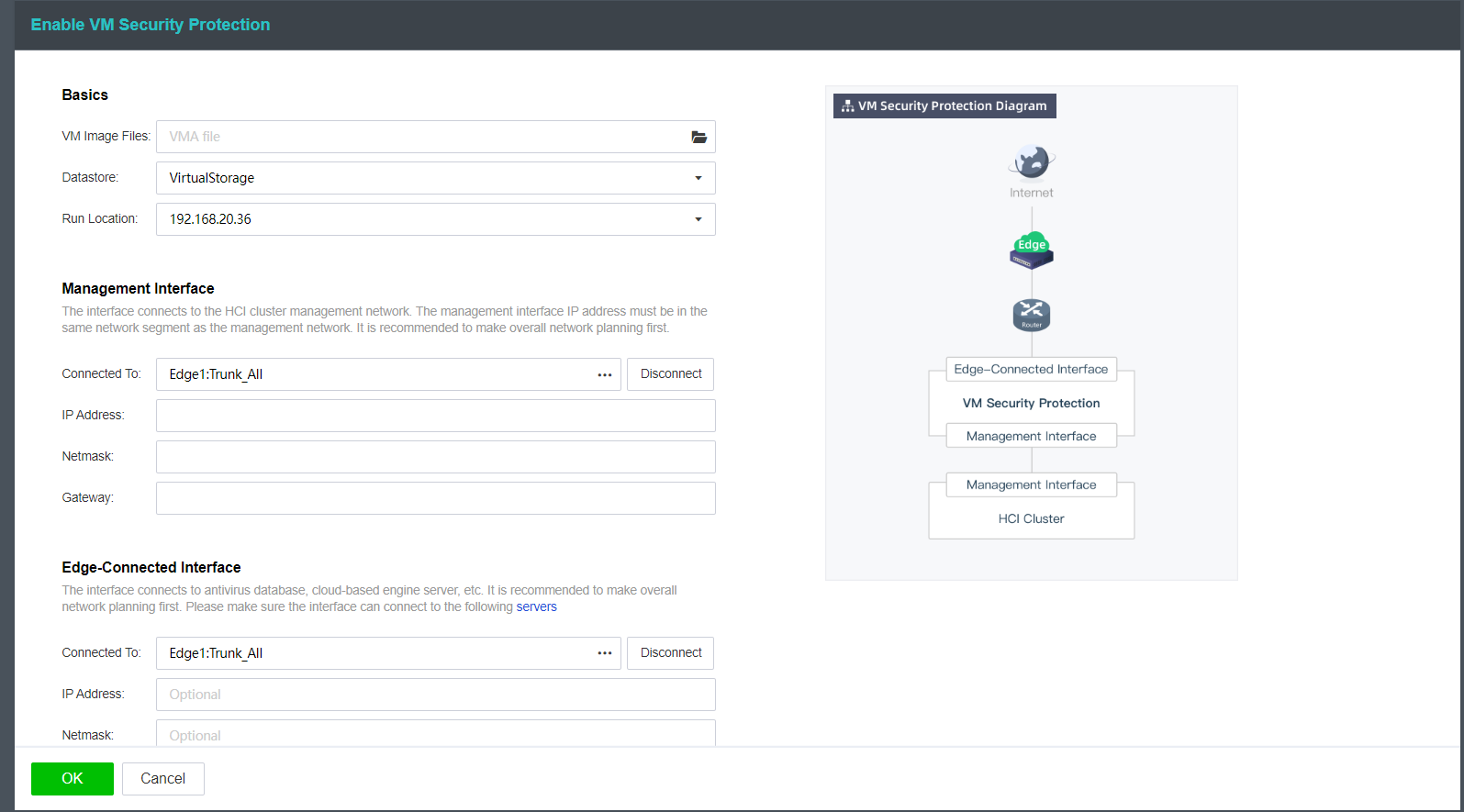
- Click the OK button to deploy the VM security protection.
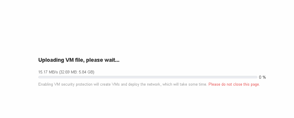
- After the successful deployment, it will automatically redirect to the Security Settings > Security Capability page. The security settings interface will pop up, where you can view the default security settings. If you need to perform other personalized configurations, please refer to Sangfor ES User Manual.
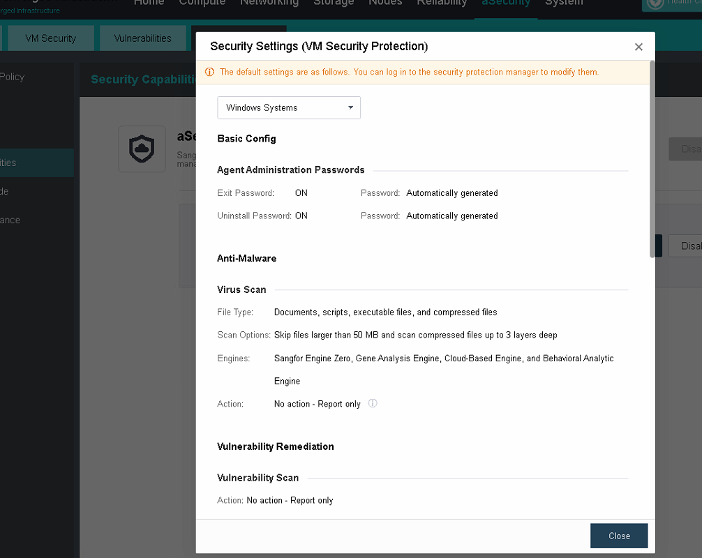
- After the deployment is complete, click Go to Security Protection Manager, enter the System > System Updates > Signature Database Update page to update the antivirus database; enter the System > System Updates > Vulnerability Database page to update the vulnerability database.
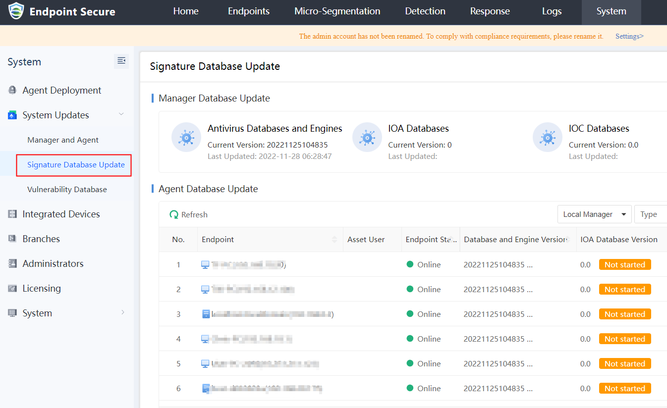
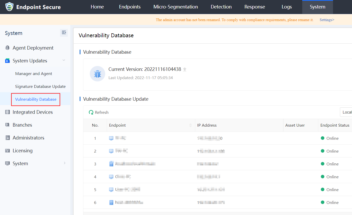
VM Security Agent Installation
Precautions
- It supports the automatic installation of the security agent on virtual machines, but the security agent cannot be automatically installed when the licensed number of aSecurity agent is insufficient.
- The estimated time for the virtual machine to automatically install a security agent is within 10 minutes.
- Operating systems not listed on the OSes supported list cannot install the security agent.
Steps
- Go to the Security Settings > Security Agents page, and check the Automatically install the security agent when installing vmTools on a VM. After the option is checked, aSecurity will automatically scan every virtual machine that is online and install the security agent through vmTools. It also supports the automatic updates of security agents via vmTools. Click on the OSes Supported button to view the support operating systems.
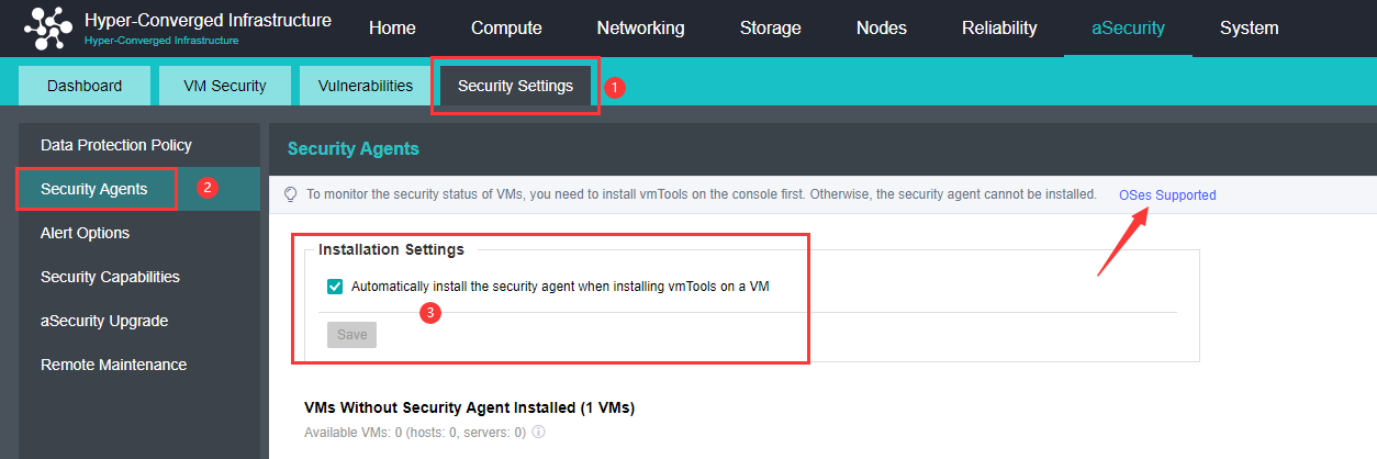
- Sangfor HCI existing virtual machines without the security agent installed.
- If the Automatically install the security agent option has been checked, the platform will automatically install the security agent for virtual machines with vmTools and is powered on status.
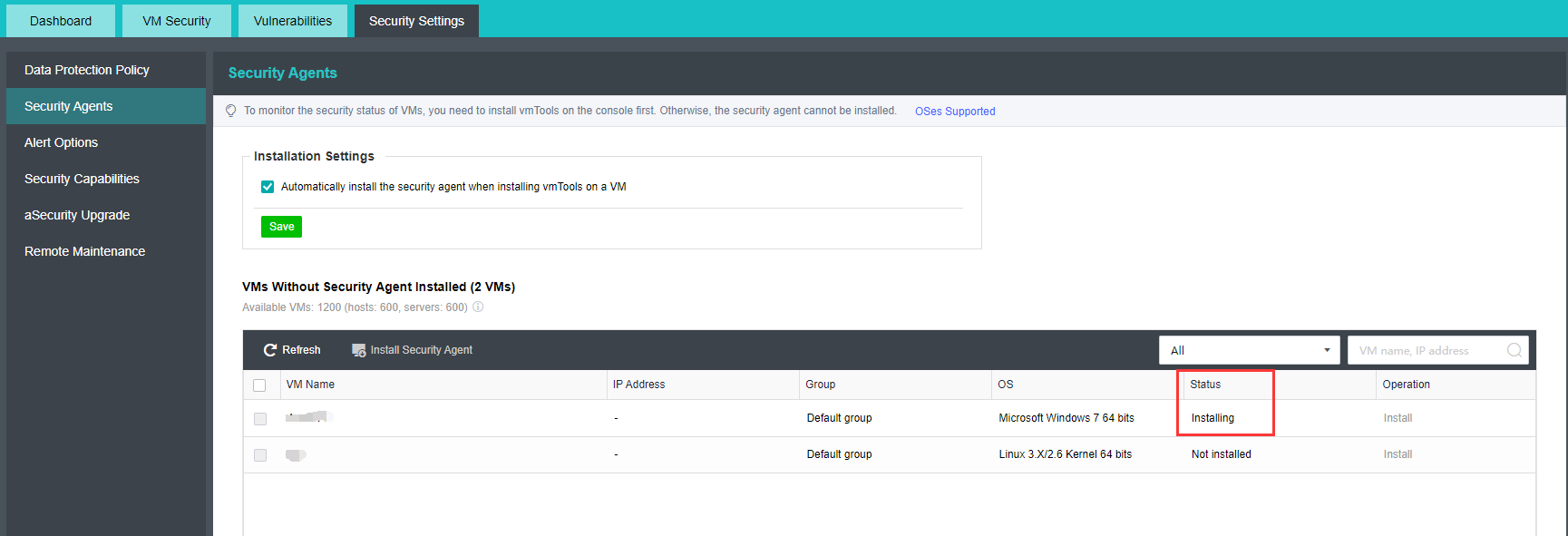
- Suppose the Automatically install the security agent option isn’t checked, and you would like to install the security agent on some virtual machines. You can select the virtual machine from the VM Name list, then click Install Security Agent.
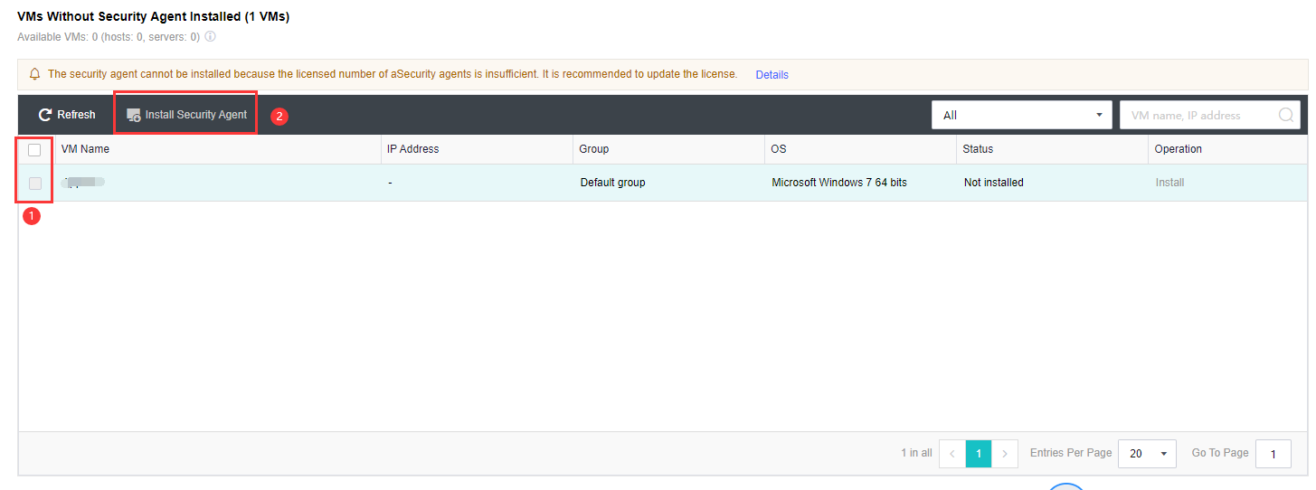
Platform Login
Prerequisites
The browser meets the following conditions: Chrome 23 or above, Firefox 18 or above, IE 10 or above, Safari 8 or above.
Precautions
- Do not refresh the virtual machine OS too frequently in the console, such as tcpdump of Linux virtual machine directly on the console, which may cause the console to get stuck.
- When two users with different permissions log in to the console in the same browser, they will replace each other’s login information, resulting in abnormal use. Do not use two users with different permissions in one browser at the same time.
Steps
- Open the browser and enter https://HCI_IP HCI platform cluster management address will open the following page.
- Enter the username and password of HCI platform. If the administrator account has set login restrictions (IP / MAC / UUID / uKey), you need to log in on the terminal that fully meets the restrictions. After successful login, you will automatically enter the console page.
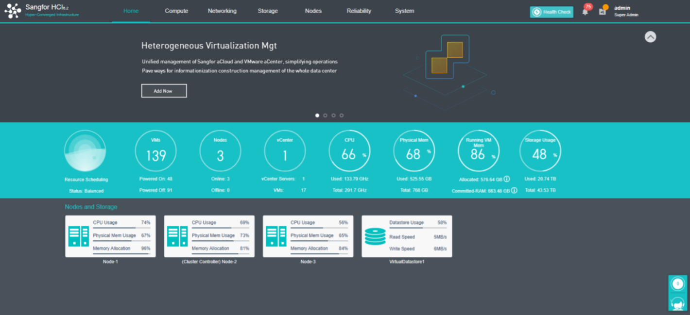
Virtual Machine Configuration Guidance
New virtual Machine
Create A New Virtual Machine
Description
When installing a new business system, you can create a new virtual machine.
Precautions
-
The windows system’s disk partitions list includes MBR and GPT. The MBR partition list supports a maximum of 2TB, and the GPT partition list supports a maximum of 128PB.
-
When installing Linux 7, please select the correct time zone and check whether the time is normal. When installing Linux 6, please check UTC and select the correct time zone.
-
When the virtual machine is started, its time base is subject to the node machine, and it is not supported to modify the time base during operation.
-
The number of cores of a single virtual machine does not exceed the number of cores of the node physical node to avoid the competition problem caused by vCPU scheduling.
-
Each virtual machine shall be configured with up to 16 virtual disks, and the single disk shall not exceed 10T. If larger capacity disks are required, it is recommended to configure multiple disks.
-
The CPU node can only be turned on when the virtual machine needs to use a special instruction set (for example, AVX instruction set is required for big data, artificial intelligence, etc.).
-
It is recommended to enable pre-allocated storage space for important virtual machines and enable High Priority. For the recycling mechanism, enable Huge-page Memory.
-
The installation of 64-bit Windows 10 and 2016 using UEFI failed. Instead of entering the installation interface, you enter the UEFI shell interface. You can enter exit in the shell interface and then enter the power on interface. Select continue in the power on interface, and then press any key to start the installation.
-
When creating a new virtual machine, the configured operating system type must be consistent with the actual installed operating system type. Otherwise, the vmTools may not be installed.
-
Red Hat Enterprise Linux 5 (RHEL 5). The disk loading order of Linux systems such as 5 is different from aSV virtual machine, which may lead to changes in the virtual machine’s disk order, the virtual machine’s inability to start or inaccessible disk, etc. You can edit the virtual machine and select the power on disk. The Linux virtual machine is recommended to use UUID to identify the disk instead of SDA, SDB, and other names.
-
The default BIOS setting for Linux virtual machines is SANGFOR LINUX UEFI. If the system cannot start after importing the virtual machine, enter the UEFI shell interface, try to shut down, and modify the setting to legacy BIOS restart.
-
After the virtual machine is suspended for recovery, the time is still the previous time, which is not synchronized with the current node time, and the time needs to be modified manually.
Prerequisites
Prepare and upload the operating system image in ISO format to the HCI platform.
Steps
- Navigate to Compute > New and select Create New VM.
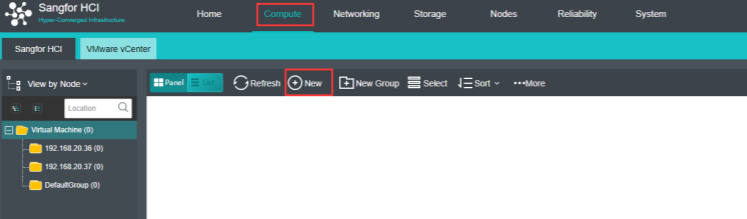
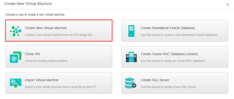
- Configure the following information.
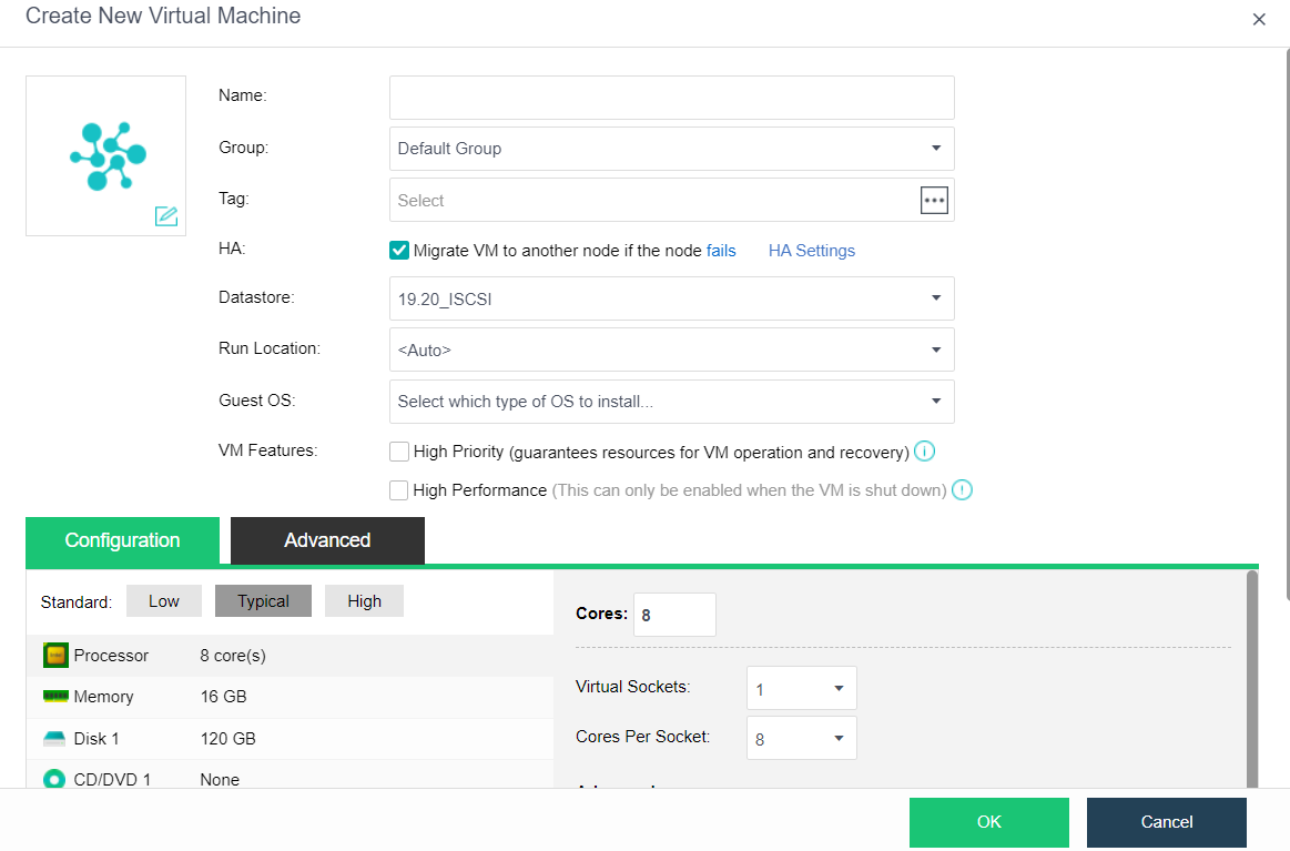
-
Name: Specify a distinguishable name for the virtual machine.
-
Group: Specify a group to which this virtual machine belongs.
-
Tag: Specify one or more than one tag for the virtual machine.
-
HA: If Migrate to another node if the node fails is selected, the virtual machine will be recovered onto another node in case the node running the VM fails.
-
Datastore: Specifies a datastore to store virtual machines. HA is configurable only when a shared datastore is selected.
-
Storage Policy: Specify the number of replication and performances.
-
Run Location: The run location specifies which node’s CPU and memory resources are used when the virtual machine runs. You can select and specify a host automatically. When the selected storage domain is selected as the run location, or when the selected storage domain is chosen as the run location, it can also be set as the default location.
-
OS: Specify an operating system for the virtual machine. The following guest OS is supported: Sangfor, Windows, Linux, Linux distributions, and others. Sangfor operating system is mainly for aCenter software.
-
High Priority: Once selected, resources will be preferentially allocated to the virtual machine if overall resources are inadequate.
-
High Performance: When selected, it is marked as an important virtual machine by default. It enables huge-page memory, uses Host CPU and Para-virtualized clock, and pre-allocating. When deselecting the High Performance, the above-enabled functions need to be turned off manually.
- Adjust The Virtual Machine Hardware Configuration
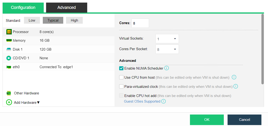
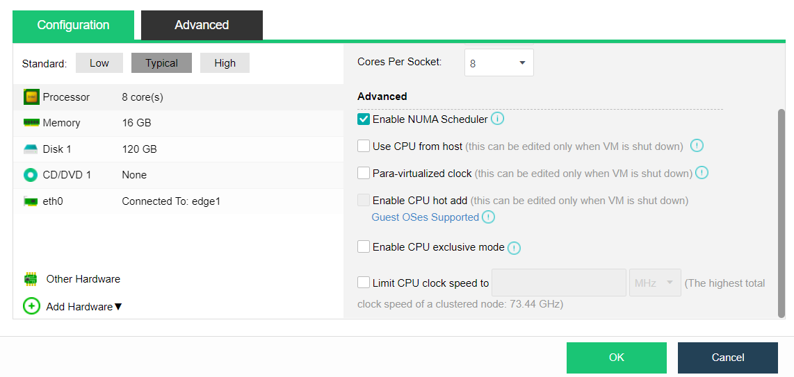
a. Processor: Specify the virtual machine’s number of virtual sockets and cores per socket. Once the Cores field is configured, Virtual Sockets and Cores Per Socket fields will automatically fill with optimum values to achieve the best VM performance.
-
Total cores = number of virtual slots * number of cores per slot.
-
Enable NUMA Scheduler: Once enabled, memory access and VM performance will be enhanced. Navigate to System > Advanced to enable the NUMA scheduler. To project NUMA topology into a virtual machine, ensure that the virtual machine has more than 8 cores and vmTools installed.
-
Use CPU from host: Live migration might be affected because of the tight association between the virtual machine and the host CPU.
-
Para-virtualized clock: It applies to Windows virtual machines only. It can improve the performance of Windows virtual machines running databases but requires enabling Use CPU from host.
-
Enable CPU hot add: Enterprise license is required, and virtual machine vmTools is installed.
-
Enable CPU exclusive mode: Once CPU hot-add is enabled, CPU resources can be hot-added manually for the virtual machine.
-
Limit CPU clock speed to: Enable to limit the upper limit clock speed used by the virtual machine vCPU. The limit range is 100mhz to 1000ghz. The recommended value will be displayed in the input box when the virtual machine runs for one week.
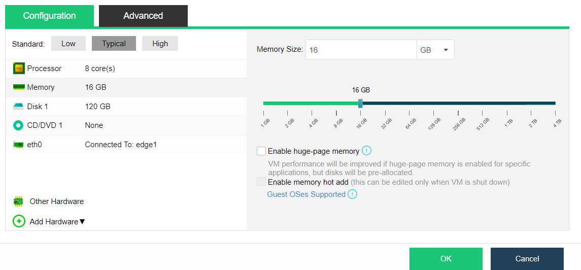
b. Memory: The virtual machine’s memory allocation does not exceed a single node’s memory.
- Enable huge-page memory: Turning on huge-page memory for a specific application can improve the virtual machine’s performance, but turning on this option will lead to memory pre-allocation of the virtual machine. After enabling huge-page memory, the memory recovery mechanism of the virtual machine will be turned off, prioritizing memory use and improving business performance.
- Enable memory hot add: Once memory hot-add is enabled, memory resources can be hot added manually for the virtual machine.
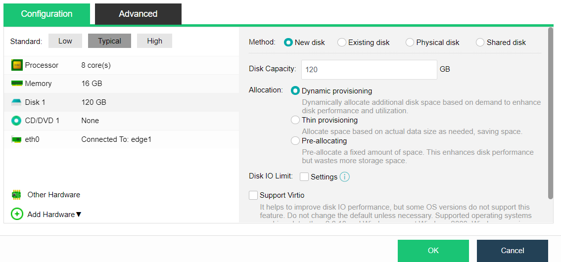
c. Disk: Virtual machine disk allocation, including the following four allocation methods.
New disk
-
Dynamic provisioning: Allocate space based on pre-allocated space and actual demands to enhance disk performance and utilization. The maximum capacity is 8T.
-
Thin Provisioning: Allocate space based on actual data size as needed, saving space with a maximum capacity of 63T.
-
Pre-allocating: Pre-allocate a fixed amount of space, enhancing disk performance but wasting more storage space., with a maximum capacity of 4T.
-
Disk IO limit: This value indicates the upper limit of disk IO that the virtual machine can occupy, configurable read/write speed, and read/write times limit. The maximum read/write speed limit range is 128KB/s-102400mb/s, and the maximum read/write times range is 16 to 2147483647. The recommended value will be displayed in the input box when the virtual machine runs for one week.
-
Support Virtio: It helps to improve Disk IO performance, but some versions do not support this feature. Do not change the default unless necessary, which may cause the disk to be missing when installing the system. It is recommended not to change the default setting.
-
Advanced setting: Stripe Width: refers to the number of stripes that can be read or written simultaneously. This number is equal to the number of physical hard disks used by a virtual machine simultaneously. This is to set the stripe number of a single disk of a single virtual machine. It is recommended to use the default setting.
Note:
After cluster initialization, the striping function is enabled by default. To ensure optimal I/O performance, the default stripe width will not exceed the number of data disks on any physical node in the virtual datastore. When upgrading from version 5.8.6 or below to version 5.8.6 or above, the virtual machine created before upgrading does not have the striping function by default. If you need to use the striping function, you need to clone one of the virtual machines created before upgrading and using the cloned virtual machine.
Existing disk
Use the disk image file of the virtual machine created earlier, such as the qcow2 format file.
Physical Disk
Mount the physical disk directly to the virtual machine to use.
Shared Disk
Select the existing shared disk, which is generally used to deploy Oracle RAC and other applications that need the shared disk.
a. CD/DVD: If the Load ISO image file is selected, you need to choose the corresponding ISO image file. You may upload an image file to the datastore from the local disk if there is no ISO image file. Click Upload from this Local Disk, select an ISO image file and upload it.
b. Eth0: Specify the NIC connection location of the virtual machine. In advanced options, you can specify the Adapter model, MAC address, and IP address of the NIC. Of which:
-
Adapter model: Virtio by default.
-
MAC address: Set the MAC address of the NIC and keep it automatically obtained or manually specified.
-
IPv4 setting: Set the IPv4 address of the NIC. Only some operating systems are supported. The supported operating systems can be viewed on the platform page, and the virtual machine can take effect only after the performance vmToolsis installed. After setting, you need to wait one minute before it takes effect.
-
IPv6 setting: Set the IPv6 address of the NIC. Only some operating systems are supported. The supported operating systems can be viewed on the platform page, and the virtual machine can take effect only after the performance vmToolsis installed. After setting, you need to wait one minute before it takes effect.
c. For other hardware and advanced configurations, kindly refer to Chapter 5.2.7 Virtual Machine Editing of this manual.
- After selecting the hardware information, select CD/DVD 1, click Browse, and click Upload from this Local PC.
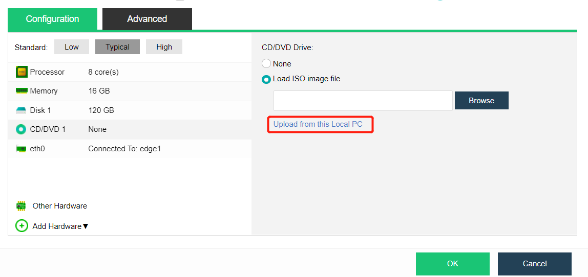
There are two ways to enter the upload interface, Image File and Datastore.
- Image File: An ISO format image prepared in advance.
- Datastore: The datastore where the image is stored.
- After selecting the local image and target datastore, click Upload.
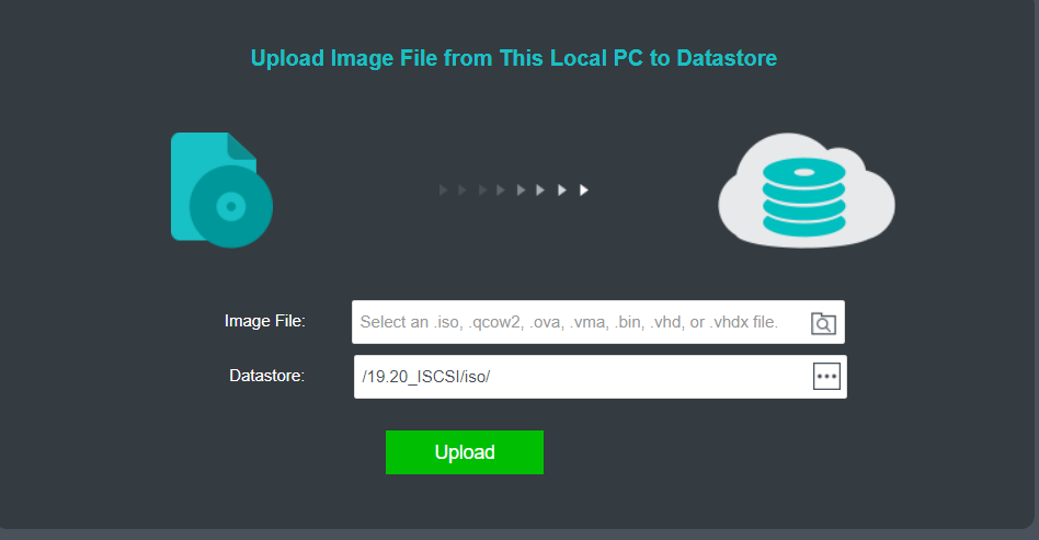
-
After uploading, open the virtual machine console to install the system. After the installation, the creation of the virtual machine is completed.
-
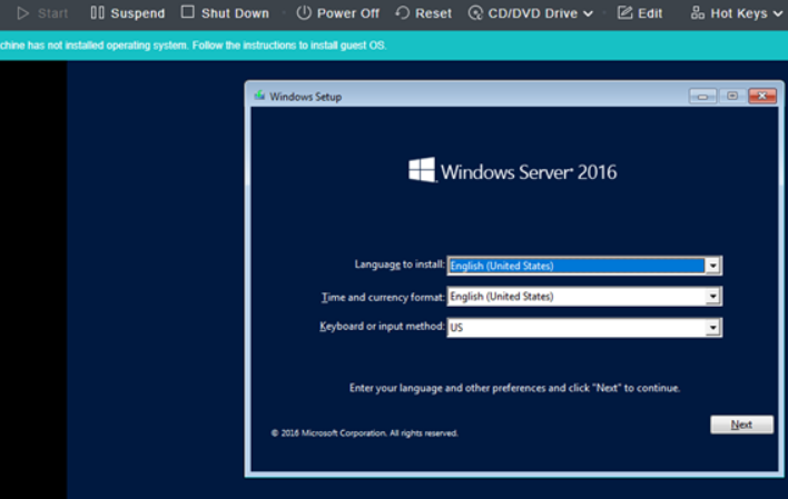
Virtual Machine Installation Operating System
5.1.2.1 Windows System Installation
Description
A new Windows 10 operating system needs to be installed for the virtual machine.
Precautions
It is forbidden to use the image on the external windows shared directory to install the operating system for the virtual machine.
Prerequisites
N/A
Steps
- Complete the configuration according to Chapter 5.1.1 Create A New Virtual Machine and enter the console.
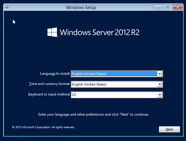
- After entering the language and other preferences, click Next to continue, click Install Now to enter the installation step, and enter the product key as prompted.
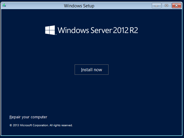
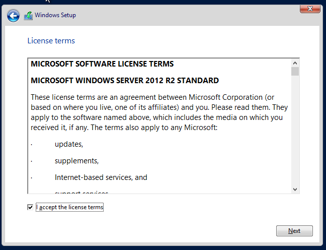
- Select the server version to be installed, including the core installation and the installation with GUI. The core installation is that Windows only has a command-line interface, and the installation with GUI exists on the desktop. Let’s proceed with the server with GUI installation.
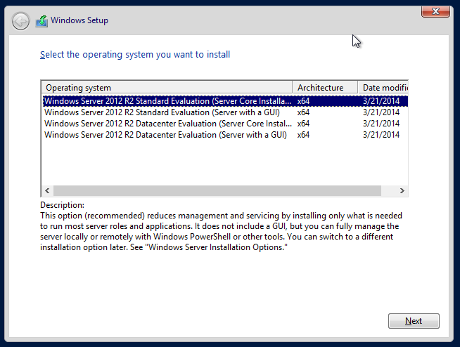
- After selection, click Next, and choose to accept the Microsoft license terms. Proceed to the next step and select custom installation.
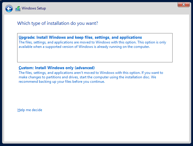
- Enter the select installation location interface. You can see the 120GB system disk we assigned, select it and click Next.
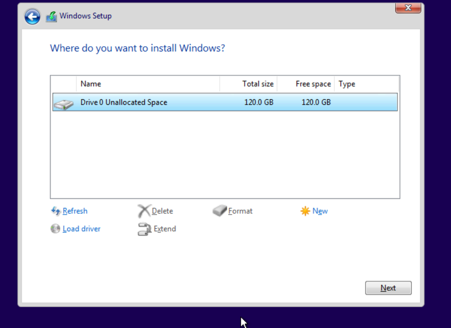
- The windows system installation and boot are complete. Please wait patiently for the installation.
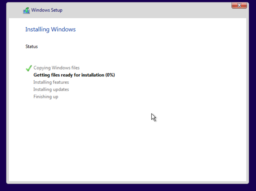
- Restart and set the account password to enter the system.
- After installation, enter the windows interface and install the vmTools. Refer to Chapter 5.2.1 Installing vmTools.
Linux System Installation
Description
A new RHEL 7.3 operating system needs to be installed for the virtual machine.
Precautions
It is forbidden to use the image on the external windows shared directory to install the operating system for the virtual machine.
Prerequisites
N/A
Steps
- Complete the configuration according to Chapter 5.1.1 Create A New Virtual Machine. Enter the console, and press enter in the installation interface to start the installation. Select the installation language (non-system language) in the first interface, and click Continue.
- Enter the installation overview interface to confirm whether the installation-related information is correct. If there is any inconsistency or need to be modified, click the corresponding option to modify.
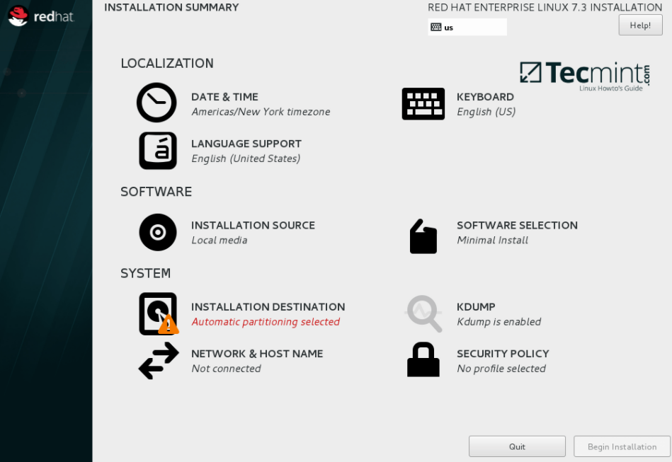
- The default software installation is the minimum installation without a GUI interface. We can click Software Selection, select Server with GUI, or install other software as needed. After selection, click Finish.
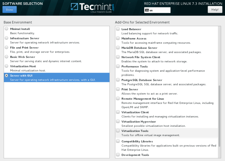
- The installation destination should be selected manually. Click Installation Destination to enter the installation destination selection interface, where you can see the allocated 20G disk. Select the disk and click Finish to automatically partition. If a manual partition is required, select I will configure partitioning to enter the partition interface.
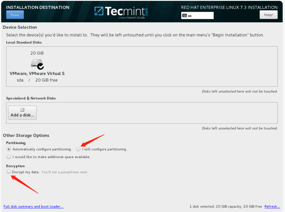
- After all the configurations are completed, the Start in the lower right corner will change to blue. Click it to start the installation. After entering the installation interface, the system is in the software installation process. The root password and user can be configured here. The installation cannot complete if the root password is not configured.
- After the system installation is complete, restart and enter the system. After completing the basic settings, you can see the desktop.

- For installing vmTools, refer to Chapter 5.2.1 Installing vmTools.
Import OVA / VMA / OVF Virtual Machine
Description
At present, there is a virtualized environment. It is necessary to export the virtual machines in other virtualized platforms into virtual machine files in VMA, OVA, or OVF format and then import them into the HCI platform.
Precautions
- If the virtual machine’s name exported from VMware Workstation is in Chinese, it cannot be imported into the HCI platform and needs to be renamed first.
- It does not support the OVA import hyper fusion platform exported by the VMware web page controller.
- All virtual machines exported from VMware must be uninstalled after being imported into the HCI platform.
Prerequisites
A virtual machine file in VMA, OVA, or OVF format.
Steps
- Select Compute > New > Import VM.
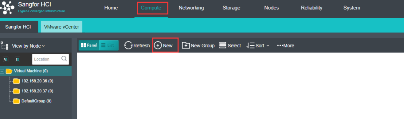
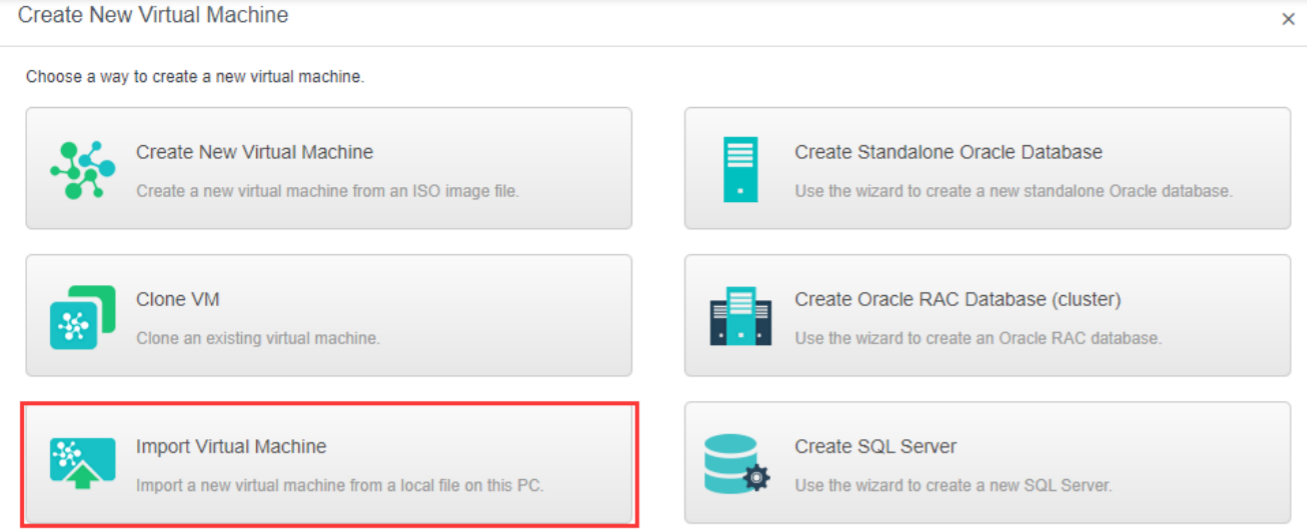
- Fill in the following information and click OK.
-
Virtual Image Files: Prepared virtual machine images in VMA, OVA, or OVF format.
-
Group: Specify a group to which this virtual machine belongs.
-
Tag: Specify one or more than one tag for the virtual machine.
-
HA: If Migrate to another node if the node fails is selected, the virtual machine will be recovered onto another node in case the node running the VM fails.
-
Datastore: Specifies a datastore to store virtual machines. HA is configurable only when a shared datastore is selected.
-
Storage Policy: Specify the number of replication and performances.
-
Run Location: The run location specifies which node’s CPU and memory resources are used when the virtual machine runs. You can select and specify a host automatically. When the selected storage domain is selected as the run location, or when the selected storage domain is chosen as the run location, it can also be set as the default location.
-
OS: Specify an operating system for the virtual machine. The following guest OS is supported: Sangfor, Windows, Linux, Linux distributions, and others. Sangfor operating system is mainly for aCenter software.
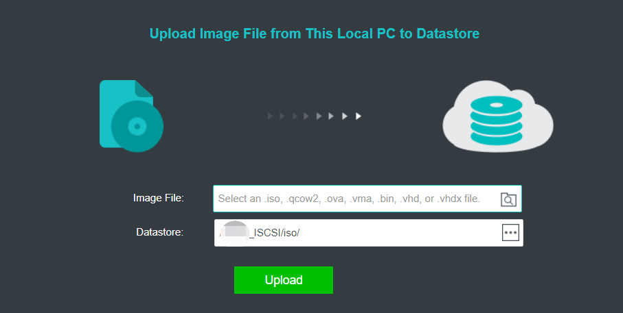
- Import the virtual machine file locally. Do not close the page during the import process.
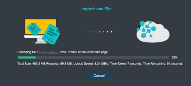
- Importing the virtual machine file locally is successful. At this time, the virtual machine NIC is not connected to the switch. Click Compute and move to the VM. Click More > Edit to enter the VM editing interface.
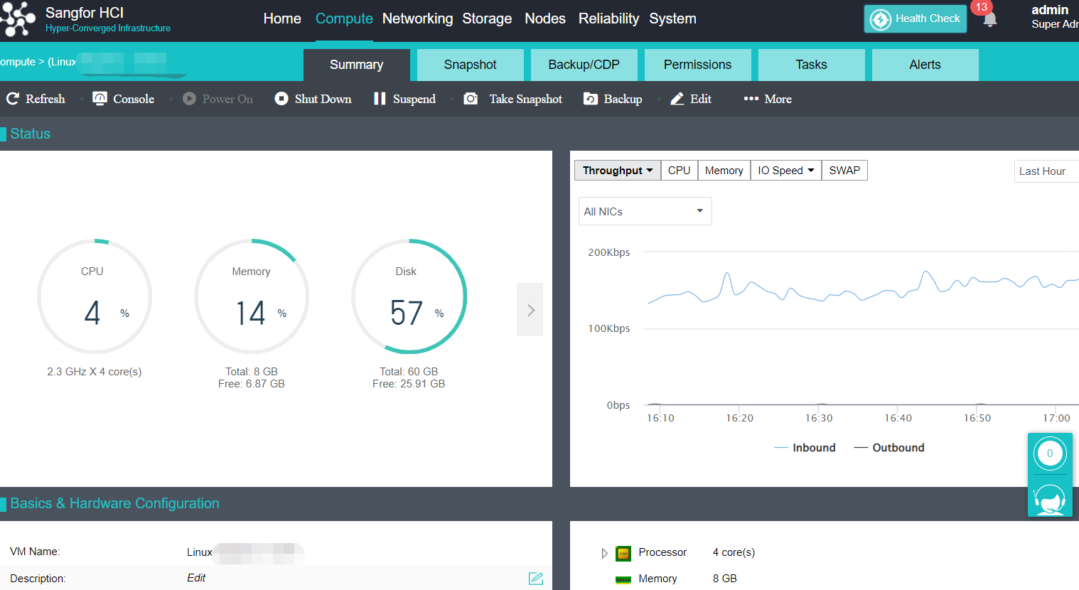
- Click eth0, select the corresponding connected device, and click OK.
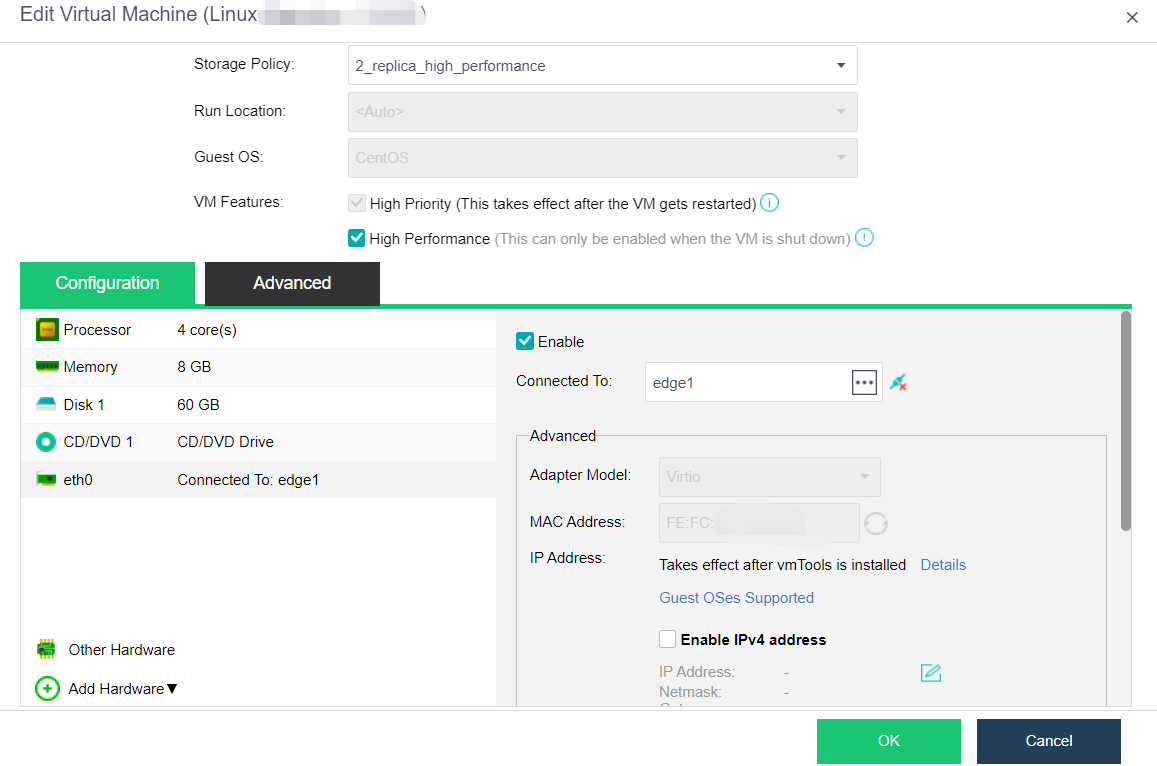
P2V Migration
Description
Package the Windows/Linux operating system and business data of the virtual machine on the existing physical node or other virtualization platforms, and clone them to the HCI platform through the network. After the migration, the original business system can continue to run as a virtual machine on the HCI platform. The original operating system will not be modified during migration.
Precautions
-
Network stability needs to be maintained during migration.
-
Operate the HCI by using Admin when using the ISO and converter tools to migrate virtual machines.
-
Suppose a disk of the machine to be migrated does not have a drive letter. In that case, if the partition size is larger than the free space of the HCI cluster and the actual occupation is less than the free space, it will report that there is insufficient HCI space during migration. Adding a drive letter to the disk without a drive letter is necessary.
-
In the P2V migration process, the data copy is completed. The agent has received the migration completion message and created a virtual machine with the existing image. The network is interrupted (when the node is offline), but the task log will fail. In fact, the migration has been successful.
-
VMware virtual machines configured with SR-IOV passthrough NICs are not supported for backup and migration to HCI. Before migration, you need to check whether the corresponding NIC type meets the VMware/virtual machines type. If it is an SR-IOV NIC, you can let customers change the NIC type of virtual machines on VMWare to other types and then migrate. The viewing method of the SR-IOV NIC is shown in the figure below.
-
After WinXP is migrated to HCI and the backup is restored to HCI, the NIC will not be restored because WinXP does not have an E1000 NIC driver. You can restore it by editing the network card type as rtl8139. After installing vmTools, the prompt to install vmTools in the upper left corner will not disappear.
-
For P2V migration using the ISO package, the physical machine memory must be greater than or equal to 3G.
-
Migration of Oracle RAC virtual machine with P2V scheme is prohibited.
-
The network is interrupted during the migration process. If you want to cancel the migration, you must cancel the source and target end. If you cancel only at the destination end, the migration will restart when the network is restored, but there will be no impact. Just cancel it again. If the network connection is normal, you can cancel the migration task at any end.
-
If the physical server of the Windows operating system is migrated from more than four disks, P2V migration is required. The Linux kernel supports viritio and can be migrated directly.
-
The windows 2008 system cannot be installed with UEFI or migrated directly. A black screen will appear. If you need to migrate, please upgrade to Windows 2008 R2 before migrating.
-
P2V the disk partitions that will not be migrated during migration. Suppose the default cluster size of the partition is FAT16 format. In that case, the partition with the allocation unit size of 2048 bytes will be automatically formatted after migration. The partition with the allocation unit size of 4096 will prompt damage. However, you can format it manually.
-
P2V the disk partitions that is not migrated during migration. If it is a partition in NTFS format, it cannot be automatically formatted after migration. After migration, it will also prompt that the partition is damaged. However, you can format it manually.
-
You can restart the client node or cancel the migration task in the task list to cancel the ongoing shutdown migration task. However, when you restart the client to cancel the migration task, the migration quota will not be released within 15min. Therefore, the task will not enter the migration state until 15mins later.
-
Before migration, check whether the customer has offline disks. For example, there are disks 1, 2, 3, and 4. Disk 3 is offline. Only disks 1, 2, and 4 can be migrated during migration. Therefore, after migrating to the target HCI, the number of the original disk 4 moves forward to become 3. After the migration, disk 4 becomes offline.
-
Use the converter to migrate. If the resolution of the migrated virtual machine is too high (test the 2K display), there will be a problem in displaying the software configuration interface. There may be no Next or Migrate button, and the resolution needs to be adjusted.
-
P2V migration does not support optimized copies of RAID-5 and Linux LVM volumes. It only supports optimized copies of simple volumes, dynamic disks (simple volumes), and cross-zone volumes.
-
P2V online migration only supports the Windows operating system and does not support the incremental migration data generated during migration.
-
P2V migration of Windows does not support the migration of external iSCSI storage data, whether turned on or off.
-
Before migration, it is necessary to ensure that the HCI license key has not expired. If the HCI license key has expired and the P2V service submission process has not been verified, the migration will fail at 99% because you do not have permission to create a new virtual machine on the HCI.
Prerequisites
N/A
Steps
Refer to the P2V Migration Guide of Sangfor HCI.
Clone VM
Instant Full Clone
Description
Through full cloning of virtual machines, you can create one or more new virtual machines that are completely consistent with and independent of the original virtual machine.
Precautions
- The information of the cloned virtual machine is completely consistent with that of the original virtual machine. The interface of the virtual machine after cloning is not enabled by default. Close the original virtual machine or modify the IP of the cloned virtual machine before enabling the NIC to avoid IP conflict.
- The cloned MAC address will change. After the virtual machine of the Linux operating system is cloned, you need to pay attention to configuring the network.
- Avoid full cloning of virtual machines during backup.
Prerequisites
Check the platform’s running task. Make sure there are no other tasks executing on the source virtual machine.
Steps
- On the Compute page, place the mouse over the virtual machine to be cloned and click More > Clone.

- Select Full cloning as the clone type, and customize parameters such as virtual machine name, number of virtual machines to be cloned, grouping, ha, datastore, storage policy, running location, etc.
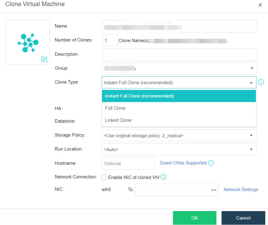
Full Clone
Description
Through rapid full cloning of virtual machines, you can create one or more new virtual machines that are completely consistent with and independent of the original virtual machine. It has the characteristics of a fast virtual machine startup, final independent data, and no impact on the performance after cloning. It is the cloning method recommended by the platform.
Precautions
The virtual machine cannot be edited during instant full clone data consolidation.
Prerequisites
The datastores of the source virtual machine and the new virtual machine must be virtual storage.
Steps
- On the Compute page, place the mouse over the virtual machine to be cloned and click More > Clone.

- Select Instant full clone as the cloning type, and customize parameters such as virtual machine name, the number of virtual machines to be cloned, grouping, HA, datastore, storage policy, running location, etc.
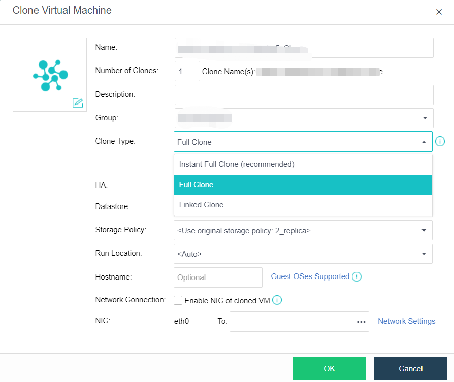
Linked Clone
Description
Through virtual machine link cloning, you can create one or more new virtual machines that are completely consistent with and independent of the original virtual machine. This mode has 1. Fast virtual machine startup. 2. Data is not independent, saving storage space. 3. After cloning, the performance will still be affected. It is recommended to use it in insensitive performance scenarios such as function development and testing.
Precautions
N/A
Prerequisites
The datastores of the source virtual machine and the new virtual machine must be virtual storage.
Steps
- On the Compute page, place the mouse over the virtual machine to be cloned and click More > Clone.
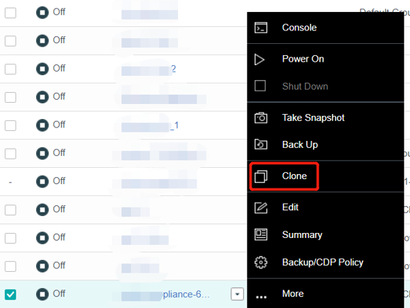
- Select Linked Clone as the clone type, and customize parameters such as virtual machine Name, Number of Clones, Group, HA, Datastore, Storage Policy, Run Location, etc.
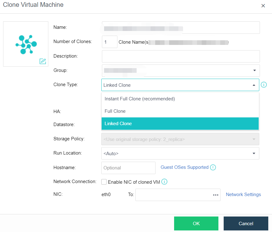
Deploying VM
Description
Through Deploy VM from template, you can create a new virtual machine that depends on the original virtual machine template and is completely consistent with the original virtual machine. After the Deploy VM from template is performed on the virtual machine, the image of the virtual machine will be used as the base image and automatically converted to the VM template. At this time, the VM template cannot be powered on or deleted. The template can be deleted only after all the virtual machines deployed by the VM template are deleted.
Precautions
- After deploying VM from the template, the VM template cannot be powered on or deleted. The template can be deleted only after all the virtual machines deployed by the VM template are deleted.
- The template deployed by the virtual machine cannot be converted to another template.
- Virtual machines with specific attributes cannot be used as VM templates, such as multiple disks. CDP policy is configured.
- Deleting templates and derived virtual machines to the recycle bin and restoring derived Virtual Opportunities from the recycle bin failed.
- Cross-storage live migration will change the derived virtual machine’s properties, and the virtual machine will become an ordinary virtual machine.
Prerequisites
N/A
Steps
- On the Compute page, mouse over the virtual machine to be cloned and click More > Deploy VM.
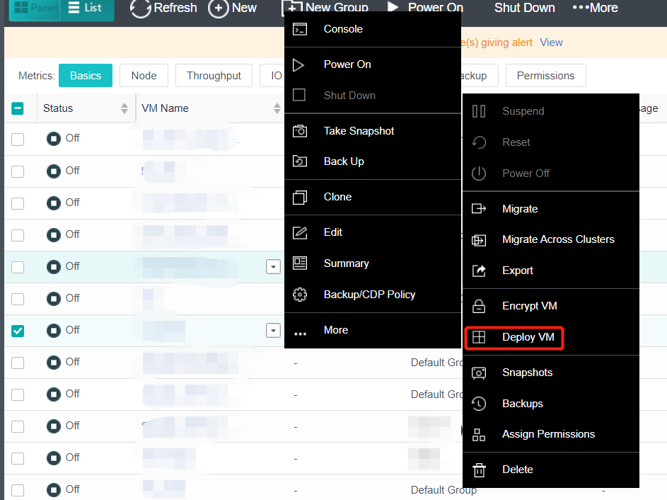
- Configure the following information and click OK to save. For more information, refer to Chapter 5.1.1 Create A New Virtual Machine in this manual.
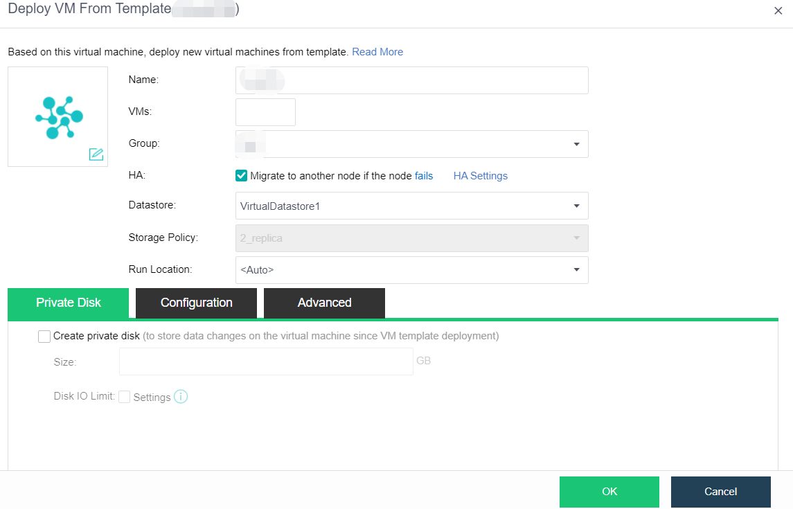
Virtual Machine Management
Installing VmTools
Windows Operating System
Description
It is recommended to install vmTools for all virtual machines running on the HCI platform, which includes drivers and applications. First, it provides high-performance semi-virtualization interface drivers to improve the performance of virtual machines. Second, it transmits the virtual machine information to the HCI platform. After successful installation, you can view the HCI platform’s CPU and memory occupancy of virtual machines.
Precautions
-
After installing the vmTools, you need to restart the virtual machine. At this time, if you forcibly power off the virtual machine from the console, it may cause a blue screen on the virtual machine. Therefore, it is best to use the guest OS’s restart function, not restart the HCI management interface’s power supply.
-
After the vmTools is installed on the Windows operating system virtual machine, if Sysprep and other system initialization operations (NIC driver will restore defaults) are required due to joining the domain, the use virtio disk option needs to be removed before restarting the virtual machine (click Uninstall on the virtual machine running status page). Otherwise, the blue screen of the virtual machine cannot be started.
-
After the vmTools is installed on the Windows operating system, the original NIC will not be deleted, a new Fast IO NIC will be added, and the name will change. A conflict will prompt if you want to rename the new Fast IO NIC to the original name. You need to delete the original NIC name from the registry first.
-
When the vmTools is not installed, the virtual machine uses the IDE bus and supports a total of 4 disks or optical drives. If the virtual machine already has four disks, you can no longer mount the optical drive and install the vmTools. You can manually copy the installation file to perform the installation or temporarily uninstall the disk and mount the optical drive.
-
Before promoting the virtual machine to the domain controller, you need to configure the IP of the NIC before installing vmTools manually.
-
The current systems supporting the installation of vmTools are shown in the table below.
| System Type | Windows | Linux |
|---|---|---|
| Support | Server version: from Windows2003SP2 to windows2019 personal version: XPsp3 to win10 | Kernel larger than 2.6.25 |
Prerequisites
The virtual machine is powered on.
Steps
Take Windows as an example:
-
Open the virtual machine console that has just imported or newly installed the operating system, and the following prompt will pop up.
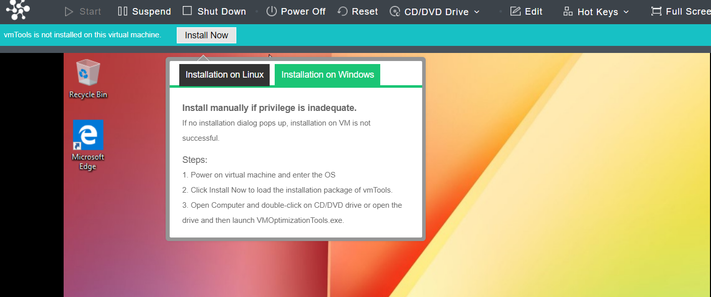
-
Click Install Now, the following page will appear, and then click Run VMOptimizationTools.exe.
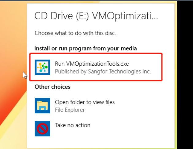
- The virtual machine desktop will prompt Installing VMOptimizationTools, please wait…

- A restart prompt, as shown below, and click Restart Now.
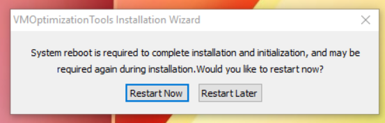
- After restart, the following prompt will pop up again. Click Restart Now.
- Place the mouse on the virtual machine where the vmTools have just been installed and click More > Summary. You can see that the virtual machine vmTools has been installed.

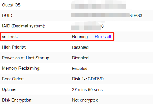
Linux Operating System
Description
Installing vmTools for all virtual machines running on the HCI platform is recommended.
Precautions
The virtual machine is powered on.
Prerequisites
The virtual machine has added a virtual optical drive. Check whether there is an optical drive on the edit virtual machine page.
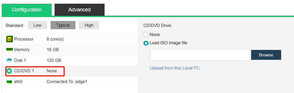
Steps
Take CentOS 6.4 as an example
- Click Install Now on the console interface to open the virtual machine console that has just imported or newly installed the operating system. The following prompt pops up on the console.

-
Mount vmTools: Create a mount point, mount /dev/sr1, and execute install.sh script. After installation, enter yes to restart the virtual machine.
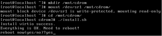
-
Confirm whether the tool is installed: Place the mouse on the virtual machine where the performance vmTools has just been installed, click the drop-down arrow that appears, and click Summary. You can see that the virtual machine vmTools has been installed.
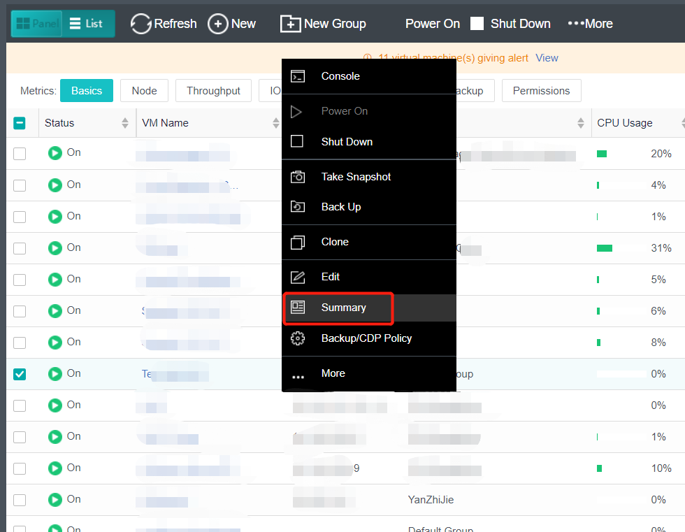
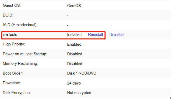
Uninstall VmTools
Windows Operating System
Description
For some reason (CPU and memory display are inaccurate), you may need to uninstall the vmTools and reinstall it.
Precautions
It must be uninstalled in the control panel. It is forbidden to uninstall with third-party tools.
Prerequisites
The administrator password of the virtual machine is required.
Steps
-
Log in to the console of the virtual machine and enter the password to enter the management interface of the virtual machine.
-
Navigate to Control Panel > Uninstall a program.
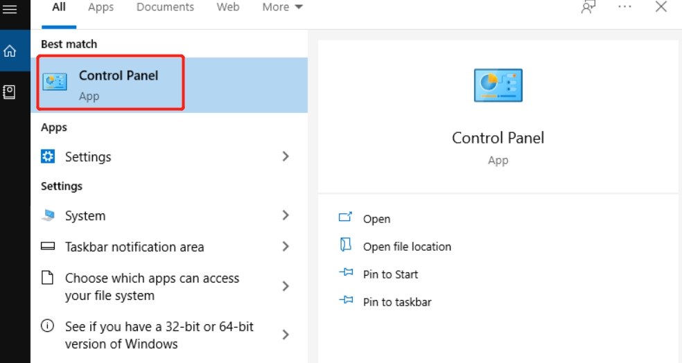
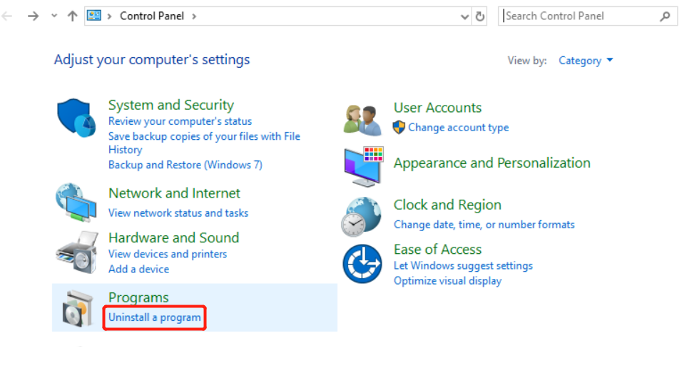
-
Looks for the VMOptimizationTools and click Uninstall/Change.
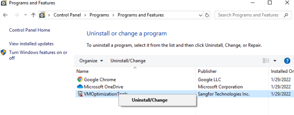
- Restart the virtual machine after the uninstallation.
Linux Operating System
Description
For some reason (CPU and memory display are inaccurate), you may need to uninstall the vmTools and reinstall it.
Precautions
N/A
Prerequisites
N/A
Steps
- Log in to the HCI console, find the virtual machine to uninstall the vmTools on the Compute page, and enter Summary.

- In the vmTools column, click Uninstall to uninstall the vmTools successfully.
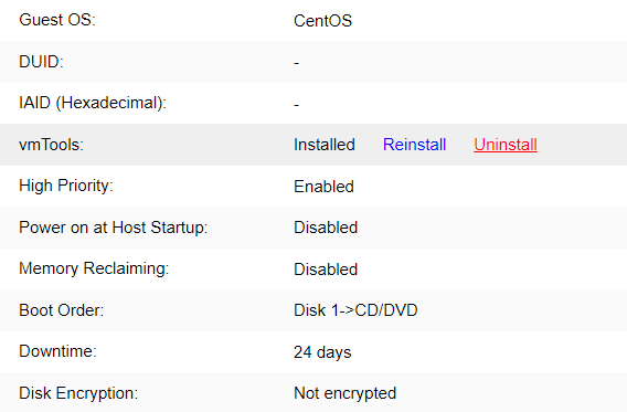
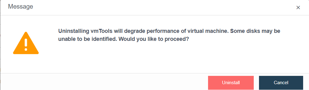
USB Mapping
Description
USB devices were originally connected to some existing physical servers. After these servers are migrated and deployed to the virtualization platform, these USB devices need to be plugged into the virtualization platform and mapped to the virtual machine. The virtual machine deployed on the virtualization platform needs to use USB devices, and the USB devices plugged into the virtualization platform need to be mapped to the virtual machine.
Precautions
- Cross host mapping is supported. For example, USB devices are plugged into node A, and virtual machines run on node A or other nodes in the same cluster as node A.
- Automatic remapping after recovery of abnormal conditions such as virtual machine fault restart and target USB device network interruption.
Prerequisites
One USB peripheral.
Steps
Take a USB flash disk as an example:
- Select any USB port access device. If there is a cluster, select any node to access USB peripherals. After connecting the USB device, the interface will be prompted, as shown in the figure below. Click Setting.
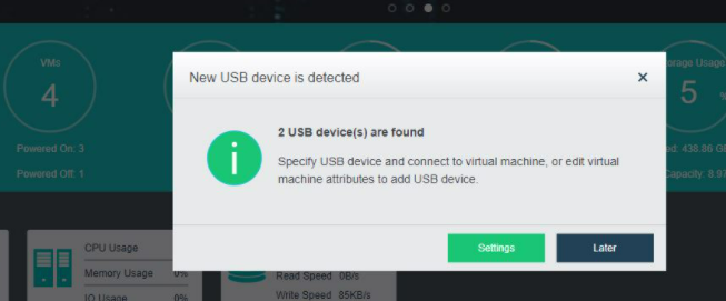
- Select the virtual machine to which the USB flash disk needs to be connected, and click OK.
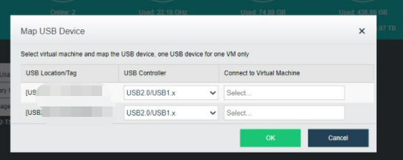
- The mapped USB flash disk can be seen in the virtual machine selected in Step 2. As shown in the figure, disk F is the connected USB flash disk.
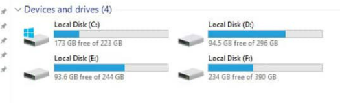
- If you want to modify the mapping between the USB flash disk and virtual machine, you can modify it on the virtual machine editing page. Place the mouse over the virtual machine to be edited, and click More > Edit.
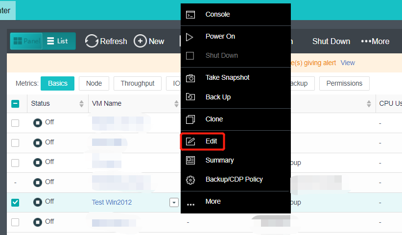
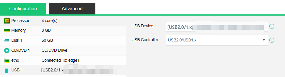
Virtual Machine Disk Capacity Expansion
Windows Operating System
Description
To expand the existing virtual machine disks and add new disks, please refer to Chapter 5.2.7 Virtual Machine Editing of this document.
Precautions
- The disk partitions list includes MBR and GPT. The MBR partition list supports a maximum of 2TB hard disk, and the GPT partition list supports a maximum of 128pb (1PB = 1024TB). Please refer to the best practice configuration for the disk size of the virtual machine.
- HCI5.8.7 and earlier versions need to shut down the virtual machine to expand the size of a single disk of the virtual machine.
- HCI5.8.8 can expand disk capacity after startup.
- Virtual machines support adding new hard disks online.
- IDE disk type does not support disk thermal expansion. Vmtools need to be installed.
- The derived virtual machine does not support system disk expansion.
- Due to the operating system itself, the Windows Server 2016 datacenter system disk does not support capacity expansion.
- Creating a dynamic disk with large storage may fail when the storage is small. For example, a 63TB dynamic disk is created on 4TB virtual storage.
- When pre-allocated disks are expanded, the disk type after the expansion is thin provisioning. For example, the original 80GB disk is expanded to the original 80GB disk.
Prerequisites
Need to install the vmTools and enable virtio disk for power on expansion.
Steps
- Place the mouse over the virtual machine whose disk needs to be expanded, and click More > Edit.
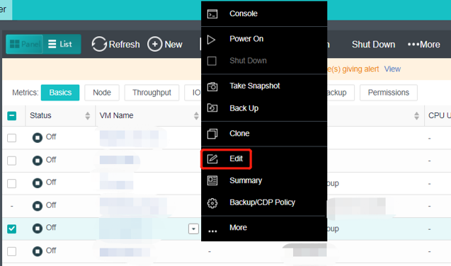
- Edit virtual machine: Increase the Disk Capacity to the required size. In this example, adjust the disk size from 80GB to 500GB, and then click OK.
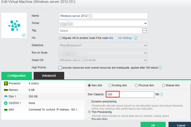
- Enter the virtual machine console: Place the mouse over the virtual machine, and click More > Console.
- Virtual machine disk management: Start > Run > diskmgmt.msc to access disk management.
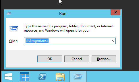
- Refresh disk information: Click the refresh button in the disk management toolbar. After identifying the newly expanded space, the new space can be used to create a new simple volume or expand an existing volume. The following demonstration is to expand a volume. As shown in the figure below.
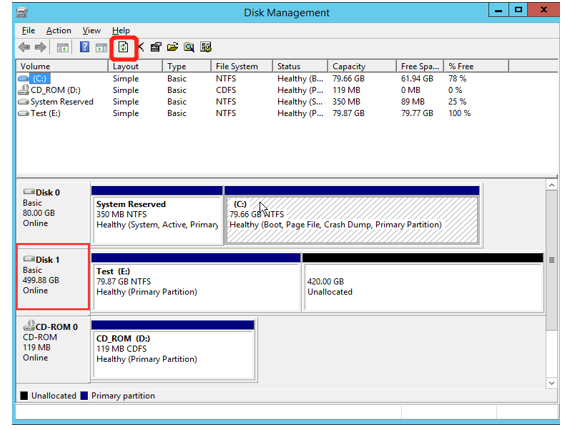
- Right-click the disk and then click Extend Volume. The expand volume wizard will pop up. The expansion process is simple. Operate according to the system prompt and will not be repeated.
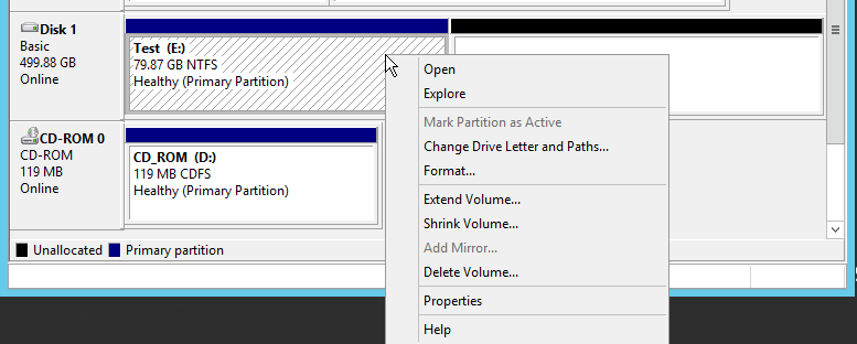
- Finish adding: As shown in the figure below, the disk expansion operation is complete.
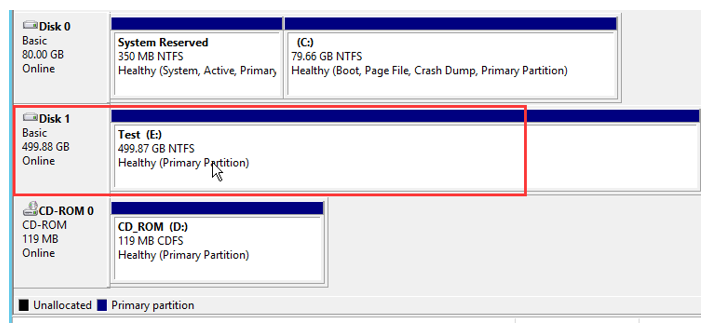
Linux Operating System
Description
To expand the existing virtual machine disks and add new disks, please refer to Chapter 5.2.7 Virtual Machine Editing of this document.
Precautions
- For virtual machines using LVM.
- HCI5.8.7 and earlier versions need to turn off the virtual machine operation to expand the size of a single disk of the virtual machine.
- HCI5.8.8R1 virtual machine supports power on disk capacity expansion and adding a new disk.
- The part of the virtual machine system in this manual is to demonstrate a feasible way of capacity expansion and the process of Linux capacity expansion. It is not the only way of capacity expansion. The operator should fully understand the significance of various commands and parameters in the demonstration and be able to make corresponding adjustments according to actual needs.
- IDE disk type does not support disk thermal expansion. Vmtools needs to be installed.
- The derived virtual machine does not support expanding the system disk.
- When the storage is small, creating a dynamic disk larger than the storage may fail.
Prerequisites
- VmTools needs to be installed, and virtio disk needs to be enabled for power on expansion.
- The following is a demonstration of using CentOS to expand the capacity of the root directory mount point.
Steps
- Edit virtual machine: Click More > Edit.
- Adjust disk size: Adjust the disk to the planned size. In this demonstration, adjust the disk from 50GB to 80GB, and click OK after modification. If the virtual machine is turned off, turn on the virtual machine and enter the console.
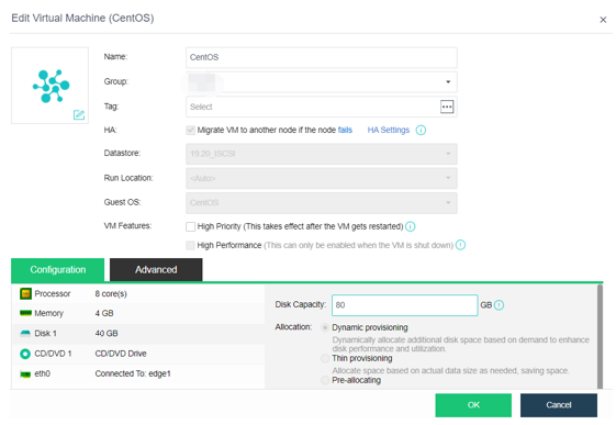
- View current information: View the expanded disk information through the "lsblk" command. The disk is "/dev/vda", vg is "volgroup", and lv is "/dev/ volgroup/lv_root".
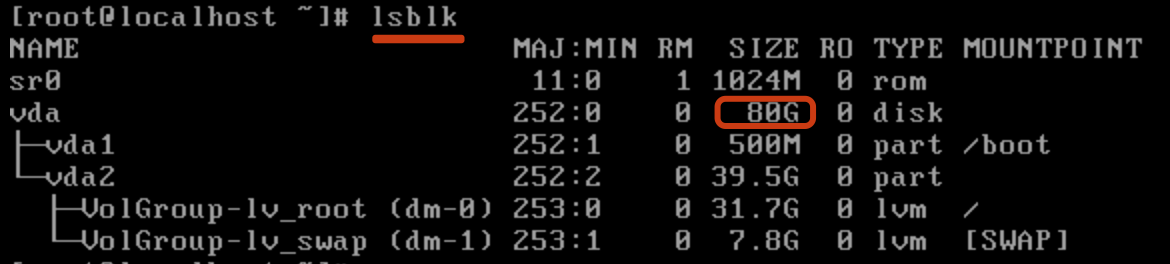
- Disk partition: Enter the disk partition through "fdisk/dev/vda" and enter "p" to view the current partition. At present, the "/dev/vda" disk in the demonstration environment already has two primary partitions. Add a new partition number of 3, the new partition device name of "/dev/vda3", and the cylinder starts from 83221.
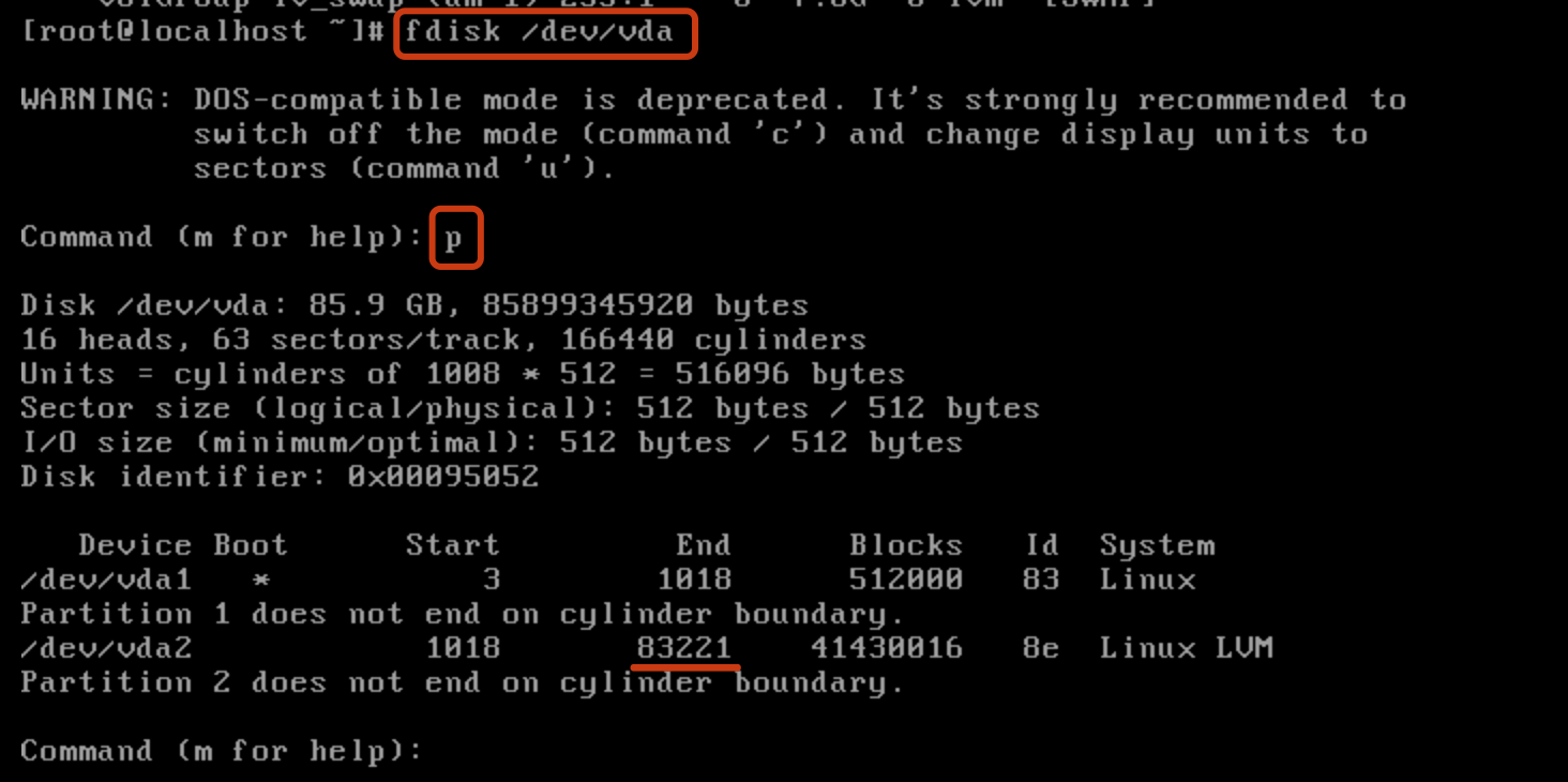
- Create new partition: Enter "n" to create a new partition; Enter "p" to create a primary partition. Enter the partition number, First cylinder, Last cylinder, then enter "w" to save the partition information and exit fdisk.
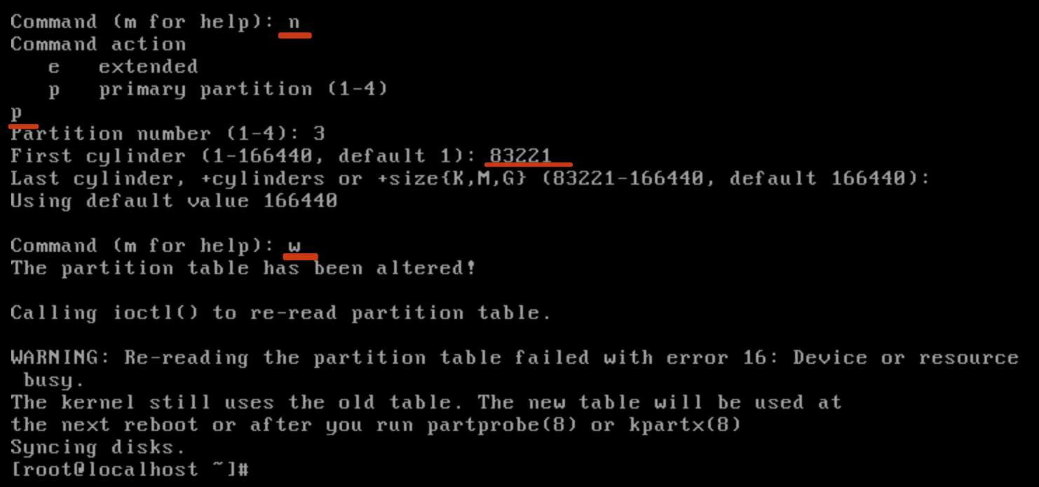
- partx: After modifying the disk partition table, you can check whether the partition is recognized through the "lsblk" command. If no new partition is recognized, there is no need to restart. With the "partx" command, the kernel can read the new partition table information.

- Check to see if the partition is recognized.
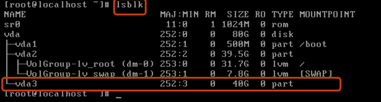
- Convert the newly added partition into PV and add it to VG and LV. After expanding the logical volume, use resize2fs to resize the partition to use the expanded space.
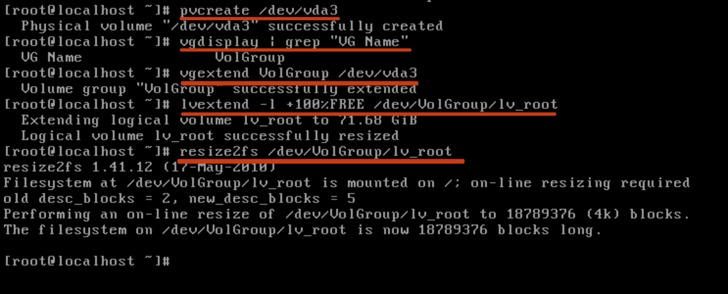
- View the lv size after capacity expansion: You can see the LV size after capacity expansion through the DF command. The capacity expansion is completed.
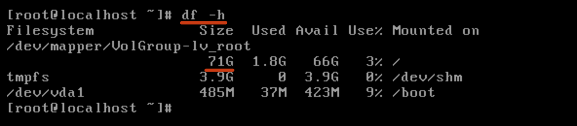
Using Physical Disks (Raw Disk Mapping)
Description
HCI supports adding external storage and directly mounting LUNs on external storage to virtual machines.
Precautions
When HCI adds external storage, first click Scan for New Disks and then click New to find external storage.
Prerequisites
The HCI host is connected to FC storage or iSCSI storage.
Steps
Take iSCSI storage as an example:
-
Configure the IP address used as the storage interface on the HCI node to enable it to communicate with the iSCSI storage server.
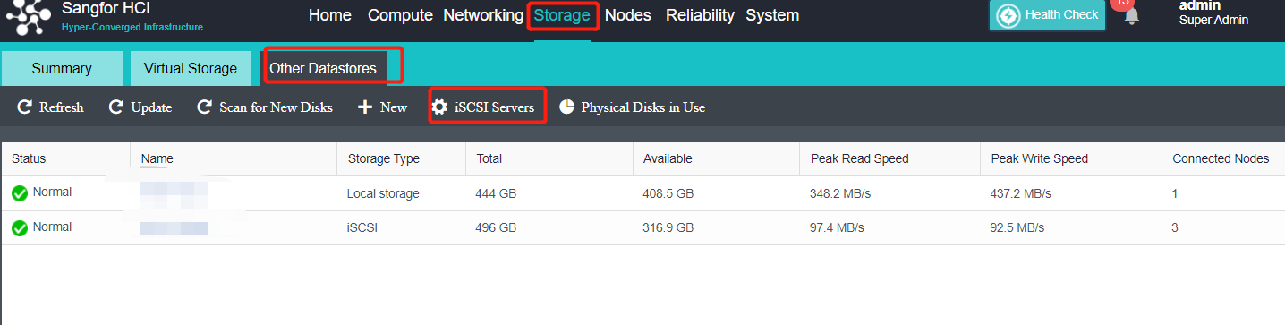
-
Make correct configuration on iSCSI storage and map the corresponding datastore to HCI nodes for use.
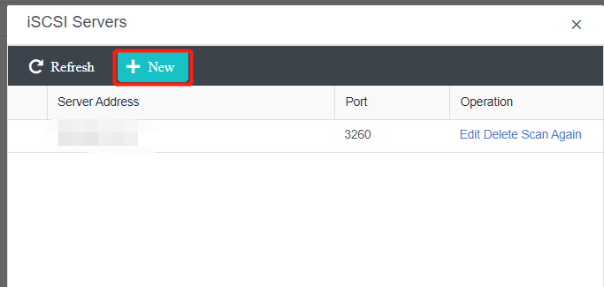
-
In Storage > Other Datastores, click iSCSI Server.
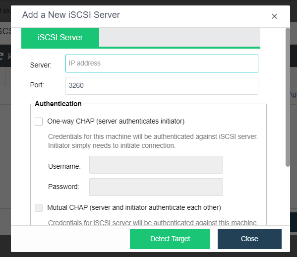
- On the pop-up iSCSI Server page, click New. The Add a New iSCSI Server window pops up.
- Enter the IP and click Detect Target.
- Then click Authentication to prompt Authenticated, and then click Close.
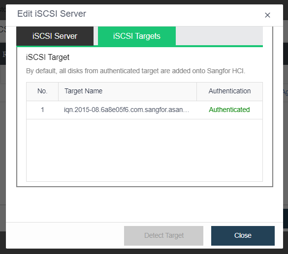
- On the Edit Virtual Machine page, click Add Hardware > Disk, select the physical disk to use, select the corresponding LUN, and click OK.
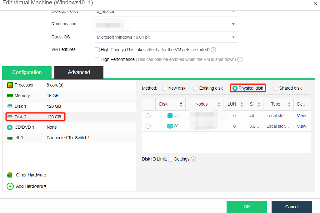
Using VHD Disks
Description
You need to mount the Microsoft VHD disk image to the virtual machine. After mounting, you can read the data in the VHD image.
Precautions
Currently, VHD images only support importing platforms and attaching to virtual machines but do not support exporting to VHD format.
Prerequisites
N/A
Steps
-
Enter the storage management page and upload the created VHD image to the specified path. After the upload is successful, the page will be refreshed to display the successfully uploaded image.
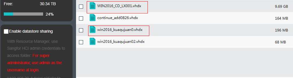
-
Create a virtual machine and select a VHD disk by selecting an existing disk.
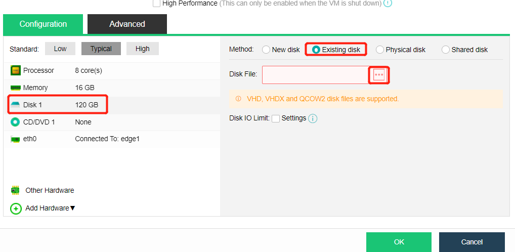
-
In addition to choosing to mount the existing VHD disk when creating the virtual machine, you can also mount the specified VHD disk by editing the virtual machine, adding disks, and selecting the existing disks.
-
After mounting, you can see the disk in the system and use the data in the disk.
Virtual Machine Editing
hardware configuration
Description
Can adjust the configuration of the virtual machine by editing the virtual machine.
Precautions
- Some operations need to be performed when the virtual machine is turned off.
- When the virtual machine maps more than two or more disks as raw disks, do not hot plug the mapped disks.
- Virtual machines started by Linux in UEFI mode on HCI cannot be exported ova to VMware.
Prerequisites
N/A
Steps
- Place the mouse over the virtual machine to be edited, and click More > Edit.
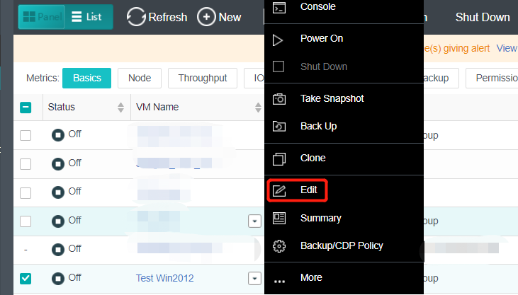
- The following information can be edited on the Edit Virtual Machine page. For more information, refer to Chapter 5.1.1 Create A New Virtual Machine in this manual.
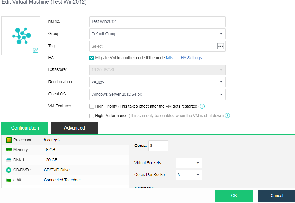
Advanced Configuration
Description
This section instructs the administrator to configure the virtual machine’s advanced options when or after the virtual machine is created.
Precautions
The Debugging in the advanced configuration of the virtual machine is not recommended to be modified by the user.
Prerequisites
Some functions need to be adjusted, and the virtual machine needs to be shut down.
Steps
- Click the virtual machine name in the virtual machine list on the Compute page to enter the virtual machine information page.
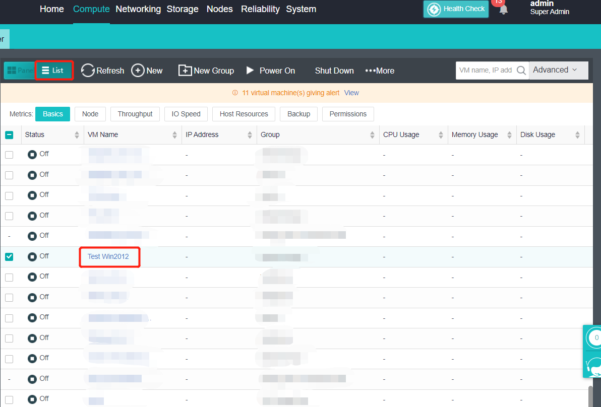
- Click Edit to enter the Edit Virtual Machine page, and then click Advanced to enter the advanced configuration page of the virtual machine.
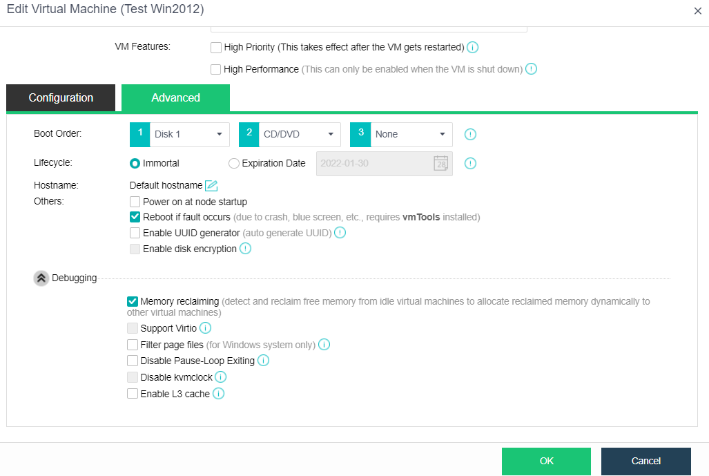
- Configure the following information
- Boot Order: Specify the boot order for the virtual machine. You can choose an item (disk or CD/DVD) from the pull-down list.
- Lifecycle: Specify the virtual machine’s lifecycle. It can be immortal or a specified expiration date. A powered-on virtual machine will occupy CPU and memory resources if it has not been used for a long period, while a powered-off virtual machine will occupy disk space if it has not been used for a long period. You can specify the Expiration Date for Lifecycle so that you may delete the expired virtual machine when the end of its lifecycle is reached.
- Hostname: you can use the default hostname of the system or manually specify the hostname on this page. However, the virtual machine must install the vmTools to use this function. Before use, you need to check whether the operating system supports it on the page. After setting, you need to wait about a minute for it to take effect.
- Others includes the following options:
- Power on at node startup: Once selected, the virtual machine will be automatically powered on once the node starts up.
- Reboot if fault occurs: Once selected, the virtual machine will be automatically restarted in case of a stuck, blue screen. To make this option take effect, vmTools should be installed.
- Enable UUID generator: Every time a UUID generator is enabled, a new UUID will be generated. Universally Unique Identifier, UUID in short, is an identifier of a virtual machine. Certain software running on the VM needs the UUID to work properly. Please do not change this since changes of UUID may cause some functionalities to be invalid. You may choose to re-generate UUID for the new virtual machine while cloning the virtual machines or to deploy the virtual machines from a template.
- To show more options, click on Debugging, and you will see the following options. However, Users are not recommended to modify them:
- Memory reclaiming: Once enabled, free memory of idle virtual machines will be detected and reclaimed for other virtual machines.
- Support Virtio: Once enabled, all disks associated with this virtual machine will support Virtio to improve IO performance, but some software versions do not support this feature. Please do not change the default setting unless necessary.
- Filter page files: Once enabled, it helps to save backup repository and time. Page files will not be filtered when a virtual machine is backed up during powered-off status. It takes effect after vmTools are installed. This debugging option is for the Windows system only.
- Disable Pause-Loop Exiting: Once selected, Pause-Loop Exiting will be disabled. Select this option to avoid VM EXIT caused by PAUSE instruction of the VM, which improves the adaptive spinning performance of multi-core VM (more than 16 cores) to some extent but requires extra costs of physical CPU. The default is recommended unless otherwise required.
- Disable kvmclock: Once selected, kvmclock will be disabled. For Linux kernel 2.6.32 or earlier versions, you may disable kvmclock to improve system stability.
Export Virtual Machine
Description
This section instructs the administrator to export the virtual machine image file in OVA or VMA format.
Precautions
Only HCI 5.2 and below support exporting VMA format. HCI version 5.2 and above supports exporting virtual machine files in OVA or VMA format.
Prerequisites
Virtual machine shutdown.
Steps
- Click the virtual machine name in the virtual machine list on the Compute page to enter the virtual machine information page.
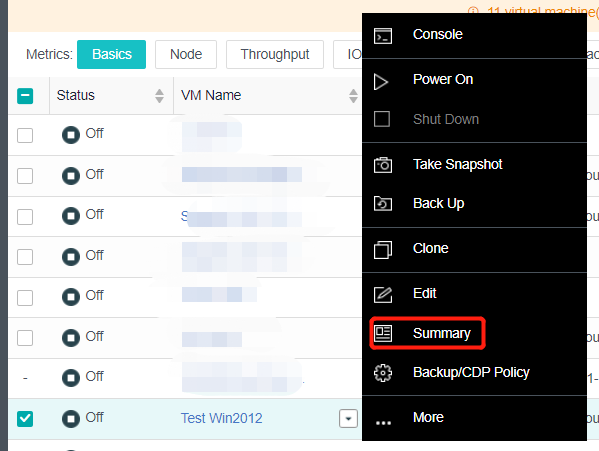
- Click More > More > Export, the Export VM page will pop up, and select the exported file format.
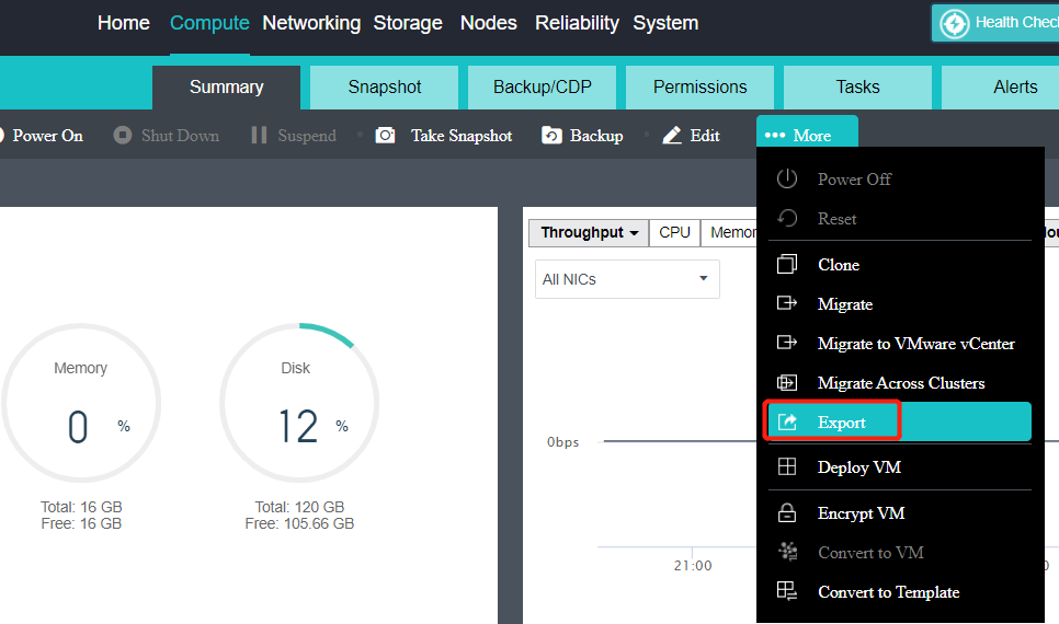
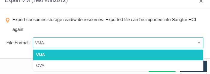
Note:
If the OVA format is selected during export, you need to select the OVA format version. Different versions of OVA run different VMware versions. For details, see the prompt selection on the interface.
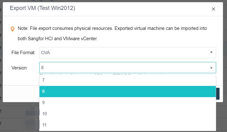
- Click Export, and start exporting the virtual machine. After some time, the export is complete.
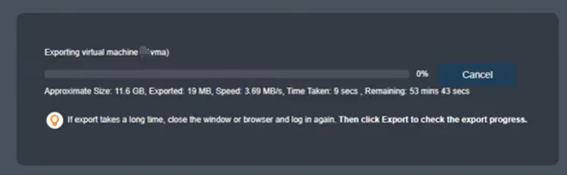
Virtual Machine Hot Migration (Supporting Batch Operation)
Description
This section instructs the administrator to migrate the virtual machine to other nodes or datastores in the cluster without shutting down.
Precautions
- Support node migration and storage migration when the virtual machine is shut down.
- Multiple virtual machines can be selected for simultaneous migration.
- Avoid migration when the virtual machine is busy. Suppose the increment is far more than the amount of data that can be migrated in the unit time cycle. In that case, the virtual machine vCPU will slow down, leading to performance degradation or even jamming of the virtual machine. If the memory incremental data cannot be migrated after vCPU slows down to 30%, the migration will fail.
- During batch migration, two tasks are allowed to be performed concurrently, and the other tasks are queued.
- During batch migration, the virtual machine’s target storage and operation location to be migrated must be consistent. Therefore, it is temporarily impossible to set the storage and operation location separately for each virtual machine.
- Before configuring the migration network, ensure that the interface of the source running node and the destination running node must be configured with IP to ensure that the migration network is available. Otherwise, it is grayed out.
- During batch migration and datastore migration, the maximum bandwidth link is used by default, there is no migration speed limit, and the setting of migration network and migration speed is not supported.
- Only when the virtual machine’s datastore is virtual storage can the migration network and migration speed be configured.
Prerequisites
The source and destination node management interfaces to be migrated are operating.
Steps
- Select the virtual machine to be migrated in the virtual machine list on the Compute page.
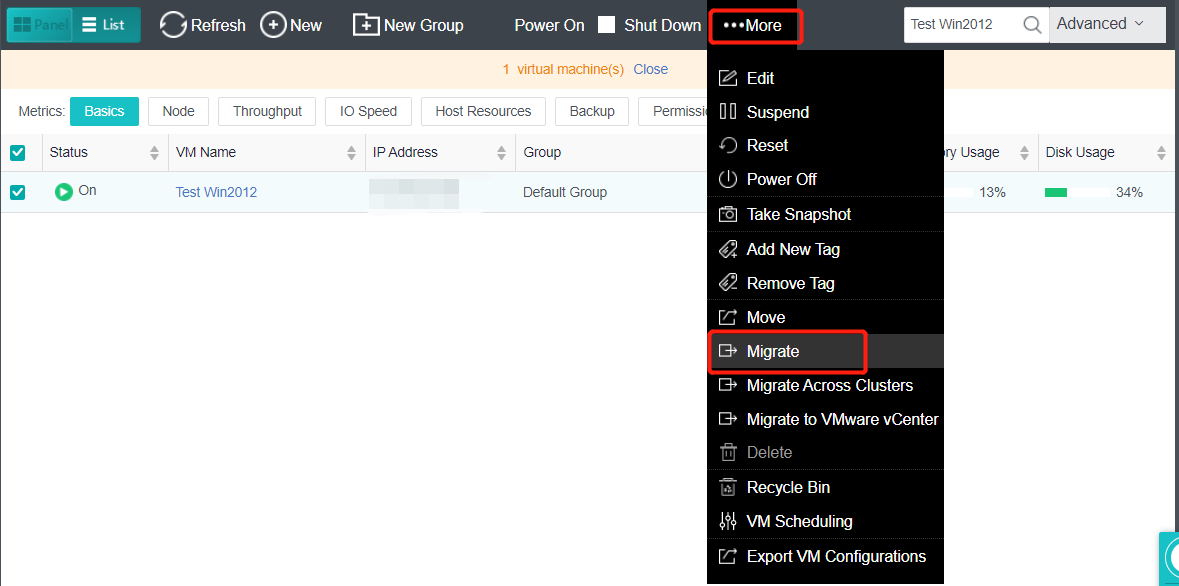
- Click More > More > Migrate, and enter the Migrate VM page. Select Migrate Type, specify destination location, and click OK.
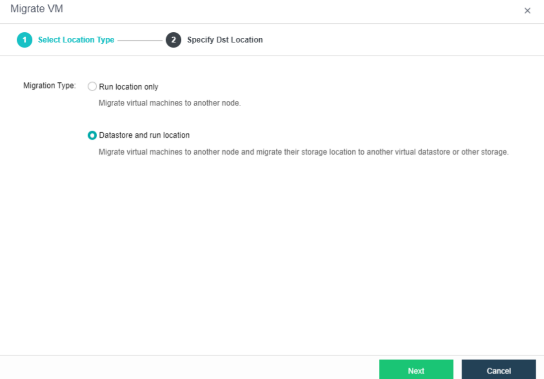
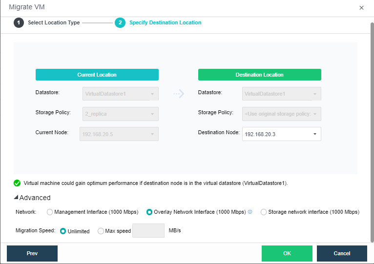
-
Click Advanced to set the Migration Network and Migration Speed.
-
Click OK, the virtual machine will enter the migration state, and the virtual machine will complete the migration.
Migrate Across Clusters(Batch Operation Is Supported)
Description
This section instructs the administrator to migrate the virtual machine to another HCI cluster without shutting down.
Precautions
- Node and storage migration can also be performed when the virtual machine is shut down.
- When migrating data across clusters, you need to manage the network. Pay attention to select the idle time for migration.
- The source and destination versions of cross-cluster migration must be the same, and both must be enterprise versions.
- The source virtual machine will shut down after the cross-cluster migration is completed.
- Limit the maximum migration rate of virtual machines across the cluster at uptime.
- Multiple virtual machines can be selected simultaneously for cross-cluster migration.
- During batch migration, two tasks are allowed to be performed concurrently, and the other tasks are queued.
- During batch migration, the virtual machine’s target storage and running location to be migrated must be consistent.
- During cross-cluster migration, the destination may report an error of image damage because the image has not been migrated. HCI detects the image every 30 minutes. If it detects that the image has not been migrated, it will report that the image is damaged. In fact, it is not damaged, but the cross-cluster migration is slow and has not been migrated.
Prerequisites
The source and destination node management interfaces to be migrated are operating.
Steps
- Select the virtual machine to be migrated: Click the virtual machine’s name to be migrated in the virtual machine list on the Compute page, and enter the virtual machine information page. Next, click More > More > Migrate Across Clusters, and enter the page of migrating virtual machines.
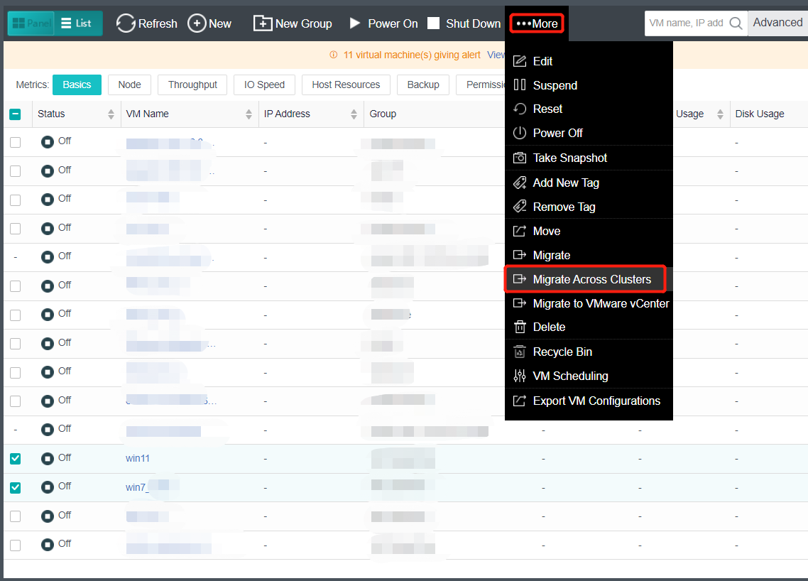
- Fill in the target cluster information: Enter the IP and password of the target cluster, and click Next.
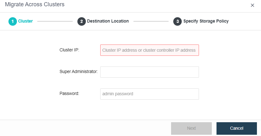
- Check the running location of the virtual machine to the destination cluster and the migration option: select the datastore and running node location of the target cluster. You can choose to check the Power on virtual machine when migration is complete checkbox and the Max migration speed per VM (the minimum rate is 5MB/s and the maximum rate is 1000MB/s.) The migration speed will be unlimited if the Max migration speed per VM checkbox is not checked. Click OK and a confirmation message pops up. Click Migrate, and the virtual machine enters the cluster live migration phase. Wait for the live migration to complete.
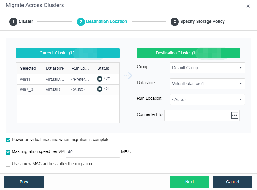
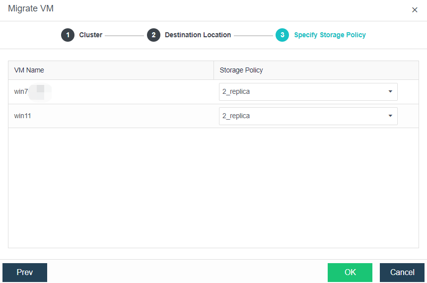

Virtual Machine Snapshot
Description
Instruct the administrator to take snapshots of virtual machines in the power-on or power-off state, often used in scenarios where the original data needs to be recovered after a virtual machine patch upgrade, software update, and other operations.
Precautions
-
A virtual machine snapshot is not used as a backup but only for virtual machine protection before high-risk operations such as virtual machine patch upgrades and software updates.
-
When aSAN virtual storage is used for three nodes and clusters above, storage snapshot (ROW mechanism based on storage) is used by default to snapshot the virtual machine. When the virtual machine has taken a snapshot on the old version platform, you can select continue to use virtual disk snapshot or switch to storage based snapshot. When switching to storage snapshots, you need to clear the virtual disk snapshots that have been created.
-
When external storage is used, a virtual disk snapshot (ROW mechanism based on qemu) is used to snapshot the virtual machine.
-
When aSAN virtual storage is used for a two-node cluster, the virtual disk snapshot is used by default, and the storage snapshot cannot be used. When the capacity is expanded to three nodes, you can switch to the storage snapshot (Need to clear the created virtual disk snapshot).
-
The maximum number of snapshots supported by storage snapshots is 48.
-
The virtual machine snapshot will interrupt the business, and the interruption time is ≤ 1s.
Prerequisites
N/A
Steps
- On the Compute page, navigate to the selected VM and click More > Take Snapshot.
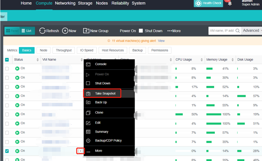
- Customize the snapshot name and description, or keep the default name. Select the Snapshot Type accordingly.
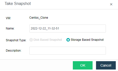
Note:
Storage Based Snapshot is only supported for three nodes or above virtual storage.
When there is an existing snapshot, it is required to delete the snapshot before changing the snapshot type.
- Click OK to complete the snapshot creation.
- You can view the created snapshot information on the virtual machine details page.
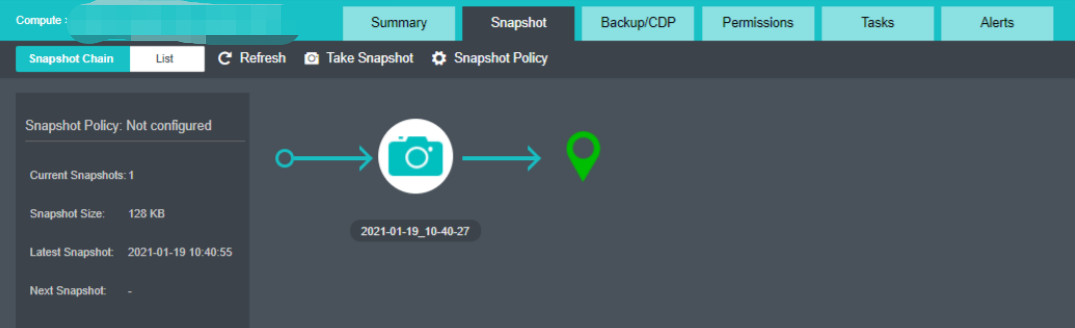
- Click the snapshot camera icon to Delete, Clone, and Restore virtual machine snapshots.
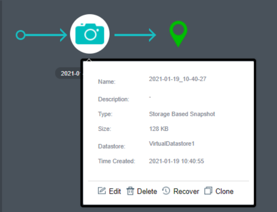
- When the virtual machine is in a power-on running state and is recovered by snapshot, the recovered virtual machine will be shut down by default. You can check the Power on virtual machine when recovery is complete checkbox to automatically power on the virtual machine after recovery. The virtual machine will be automatically powered on after recovery.
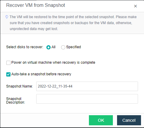
Consistency Group Snapshot
Description
Add Oracle RAC virtual machines or multiple virtual machines of a business to the consistency group to implement consistent snapshots of the whole group of virtual machines. Ensure multiple virtual machines’ snapshot data are generated simultaneously, and the business is available after snapshot recovery.
Precautions
-
The snapshot taken before the virtual machine is added to the consistency group is not allowed to be rolled back, but the virtual machine can be cloned using the snapshot.
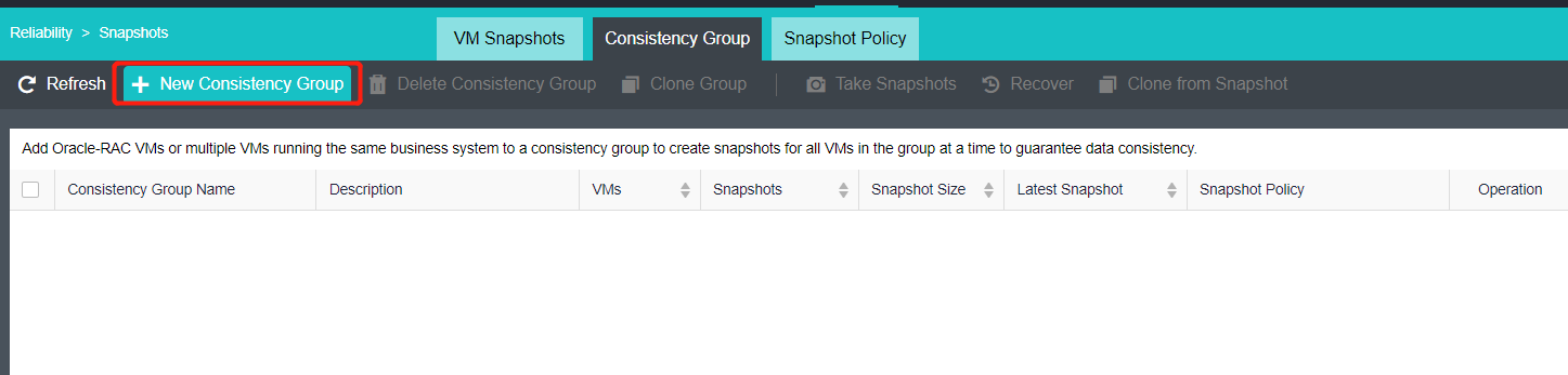
-
Consistency group snapshots are only for virtual disks and shared disks on virtual storage. Disks that are not in virtual storage will not generate snapshot data.
-
The consistency group snapshot limits the number of disks. The total number of virtual machine disks in the consistency group cannot exceed 64.
Prerequisites
Required virtual storage with 3 nodes and above.
Steps
- Click Reliability > Snapshots to enter the consistency group snapshot.
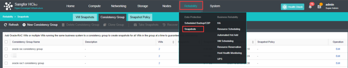
- Add a consistency group, select the associated virtual machines, and add them to the consistency group. After the virtual machine is added to the consistency group, the consistency group can be cloned to ensure the data consistency of the virtual machine after cloning.
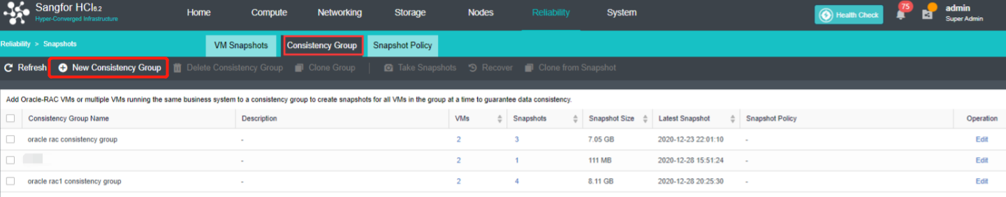
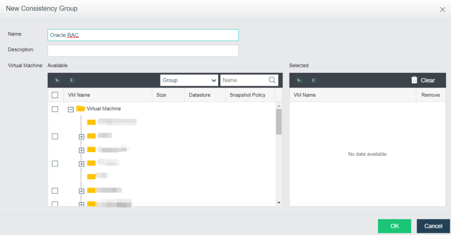
- Delete Consistency Group: Delete the selected consistency group. Required to enter the admin password to proceed.
- Clone Group: Clone the VM inside the consistency group and create a new consistency group with the cloned VM.
- Take Snapshots: Take snapshots for the selected consistency group.
- Recover: Recover snapshot for the selected consistency group.
- Clone From Snapshot: Clone VM from the selected snapshot.
Snapshot Policy
Description
It supports the automatic creation of snapshots by creating scheduled snapshot policies for virtual machines, such as snapshots of virtual machines by hour, day, and week. It supports the configuration of snapshot retention policies. Snapshots exceeding the retention range will be automatically deleted to free storage space.
By setting the snapshot policy, the virtual machine can be protected regularly. In case of logical errors, such as virus infection, the virtual machine can be rolled back by using the snapshot to recover the virtual machine and reduce the loss.
Precautions
- The continuous storage of snapshots will have a certain impact on the virtual machine’s performance. Snapshots outside the time period will be merged to save a lot of space. At least the last five snapshot files and, at most, seven snapshots will be retained.
- If the selected virtual machine or consistency group already has a snapshot policy, it will be removed from the original policy and added to the current policy.
Prerequisites
Required virtual storage with 3 nodes and above.
Steps
- Users can configure a scheduled snapshot policy to take snapshots for the VM periodically under Reliability > Snapshots > Snapshot Policy.
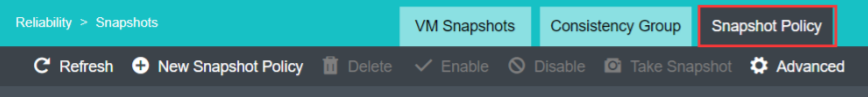
- Click New Snapshot Policy, create a snapshot policy according to the virtual machine business type, and select the virtual machine or consistency group that needs scheduled snapshots.
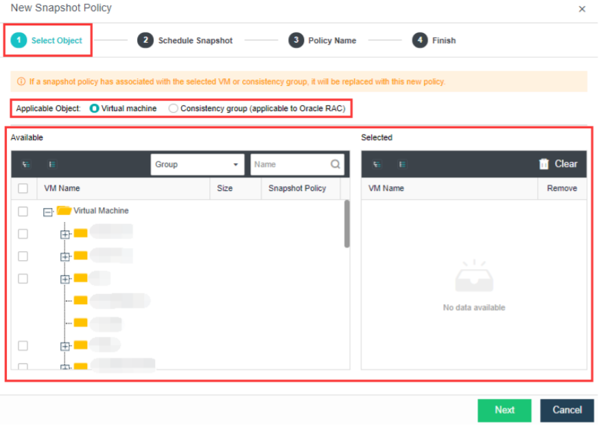
- Set the schedule snapshot according to the actual needs. You can take snapshots by week, day, and hour. In addition, you can set the retention method of snapshots to save storage space.
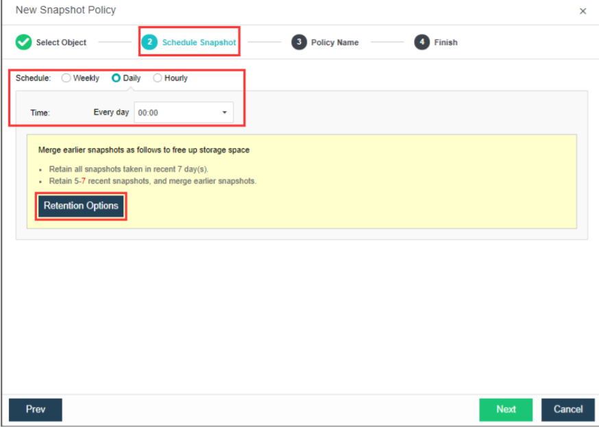
- After filling in the basic information, confirm and complete the snapshot policy.
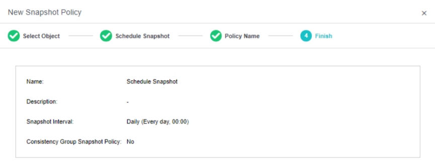
Export Virtual Machine Report
Description
Export the configuration information of the virtual machine as an Excel file.
Precautions
N/A
Prerequisites
N/A
Steps
All virtual machine configuration information of the HCI platform can be exported by navigating to Compute > More > Export VM Configurations.
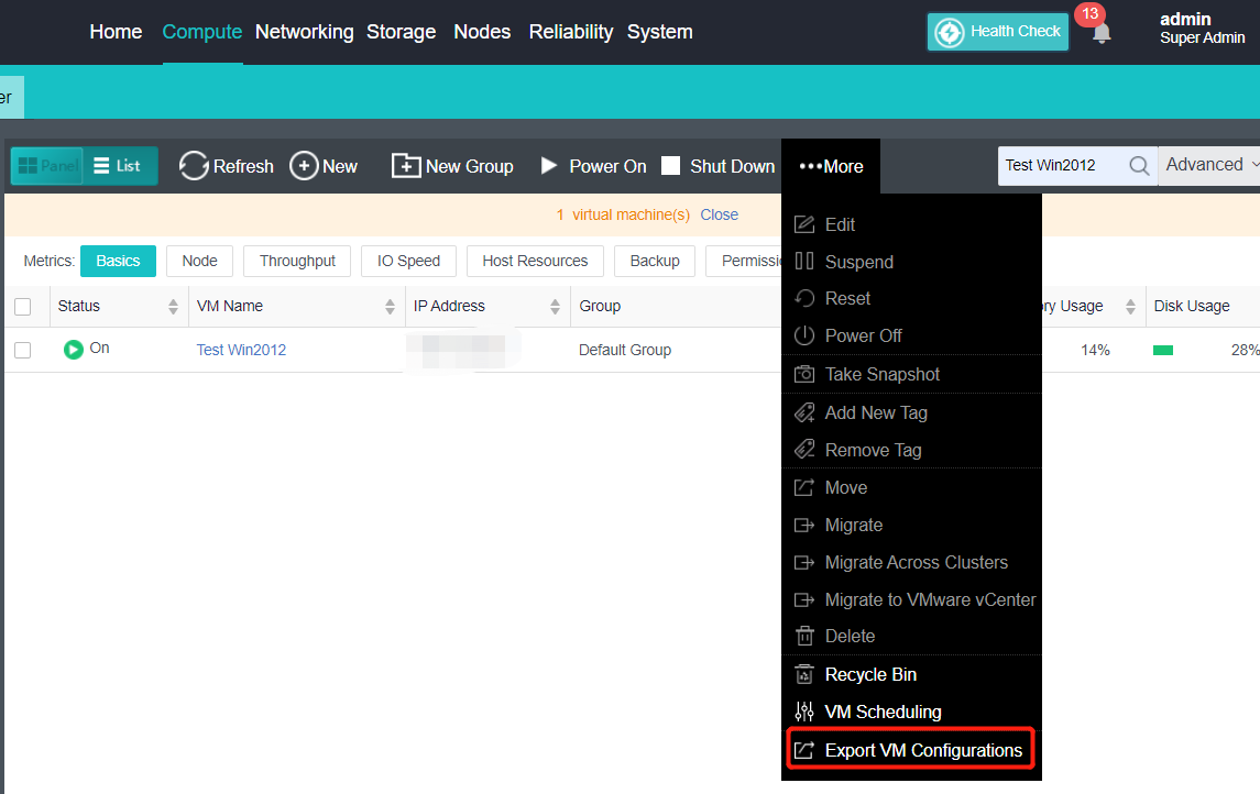
QoS Limit of Virtual Machine
CPU Clock Speed Limit
Description
This section instructs the administrator to limit the large consumption of resources by abnormal virtual machines and ensure that other normal virtual machines have sufficient resources to use. It also supports setting in the power on state. When the virtual machine runs for one week, it will generate a recommended value and display it in the input box. The CPU frequency limit range is 100MHz-1000GHz.
Precautions
- If the CPU clock speed limit of the virtual machine is too low, such as 100MHz, there may be a risk that the report data of the virtual machine is not updated in time and the virtual machine is restarting internally.
- On a Windows virtual machine with vmTools installed, the virtual machine may have a CPU limit set, but the CPU usage in the operating system and the CPU usage displayed by the virtual machine report have not decreased. You need to check the CPU usage of the virtual machine in the platform backend.
Prerequisites
N/A
Steps
- Check the virtual machine to be operated on the Compute page, and click More > Edit to enter the Edit Virtual Machine page.

- Click Processor to enter the processor information interface, check the Limit CPU clock speed checkbox, set the limit value, and click OK.
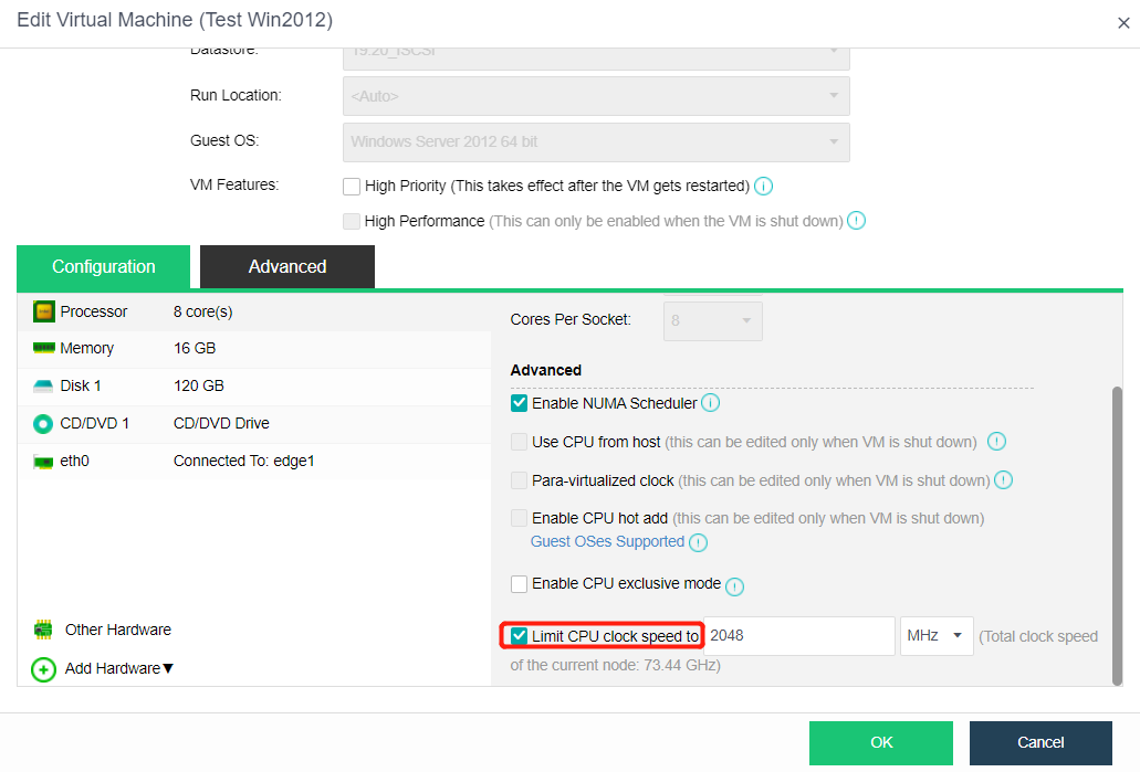
Disk IO frequency limit
Description
This section instructs the administrator to limit the upper limit of resources used by non-important virtual machines to ensure that important virtual machines have sufficient resources to use. Settings are also supported in the power-on state. The disk’s maximum read/write speed and maximum read/write speed can be limited. When the virtual machine runs for one week, a recommended value will be generated and displayed in the input box. The maximum read/write speed range is 128KB/s-102400MB/s, and the maximum read/write times range is 16 to 2147483647.
Precautions
If the IO limit of the virtual machine system is too low, such as 128KB/s, there may be a risk of the internal restart of the virtual machine.
Prerequisites
N/A
Steps
- Check the virtual machine to be operated on the Compute page, and click More > Edit to enter the Edit Virtual Machine page.

- Click Disk to enter the disk information interface, check the Disk IO Limit checkbox, set the limit value, and click OK.
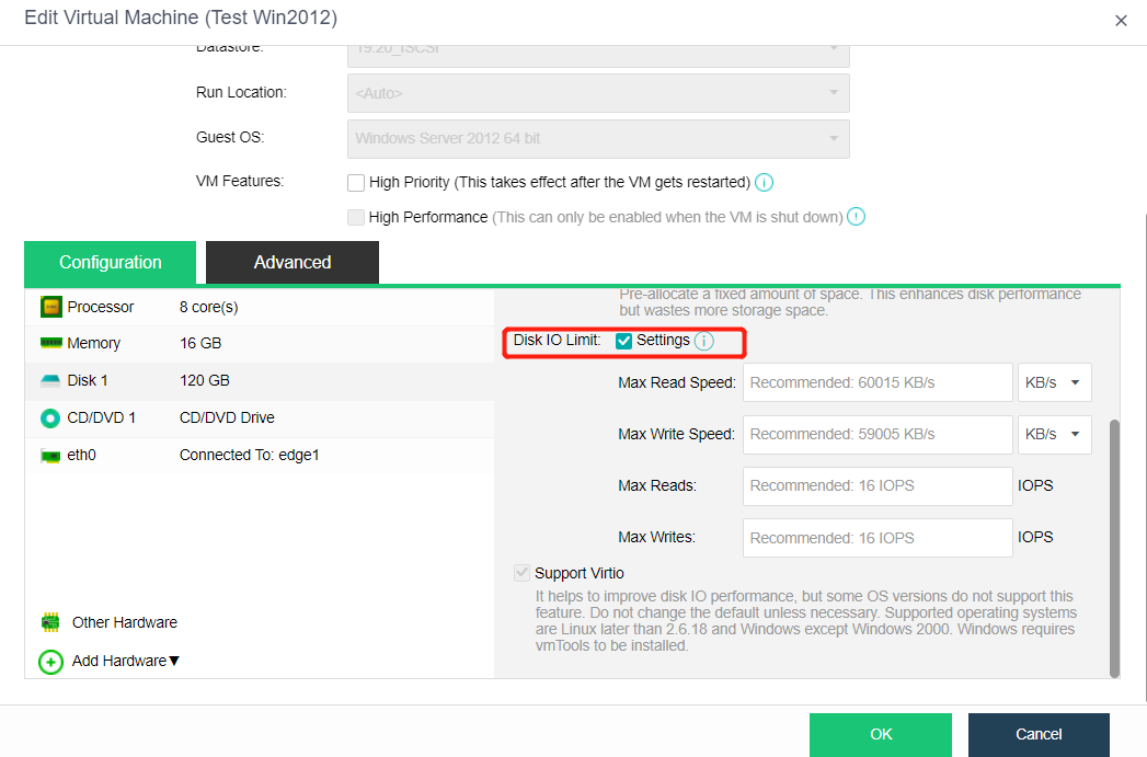
VM NIC Traffic Limit
Description
During the peak production scenario, the QoS function can limit the NIC traffic of non-important virtual machines to ensure the smooth operation of core services or virtual machines. Sangfor HCI supports Outbound/Inbound QoS settings for a single NIC to limit the network bandwidth of virtual machines.
Precautions
- The outbound and inbound traffic limit range of virtual machine NIC are between 1000Kbps-20000Mbps.
Prerequisites
N/A
Steps
- Navigate to Computer and, select the target virtual machine, click More > Edit to enter the configuration page.
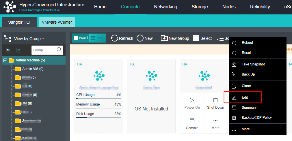
- Click the NIC where the traffic needs to be limited, enter the NIC information interface, check Enable for traffic limit, set the value for outbound and inbound traffic limit, and click OK to save.
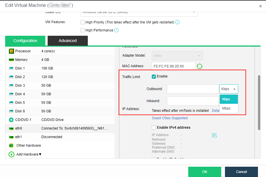
Multilingual Keyboard Support
Description
This section instructs the administrator to switch to the multi-language keyboard input mode, which can support German, French, Spanish, Italy, and other keyboard input. The American English keyboard is used by default.
Precautions
- The virtual machine keyboard type only supports editing in the shutdown state.
Prerequisites
N/A
Steps
- Check the virtual machine to be operated on the Compute page, and click More > Edit to enter the Edit Virtual Machine page.
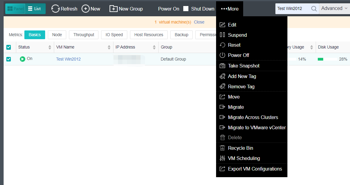
- Click Other Hardware to enter the hardware information page and set the virtual machine Keyboard Type.
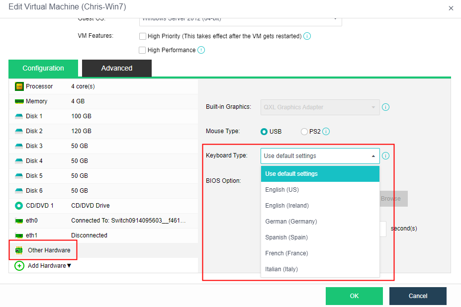
View Virtual Machine Running Status
Description
This section instructs the administrator to view the basic running status of the virtual machine.
Precautions
N/A
Prerequisites
N/A
Steps
- Click the virtual machine name in the virtual machine list on the Compute page to enter the virtual machine information page.
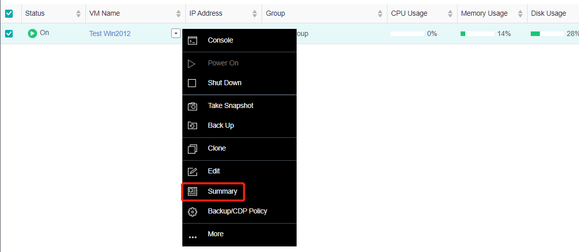
- Check the virtual machine’s CPU, Memory, and Disk capacity utilization on the Summary page.
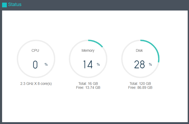
- View Throughput, Flow Rate, CPU trend, Memory, IO Speed, and IO SWAP.
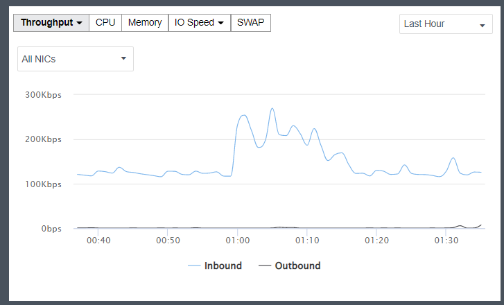
- View the basic information of virtual machine and hardware configuration information in Basic & Hardware Configuration.
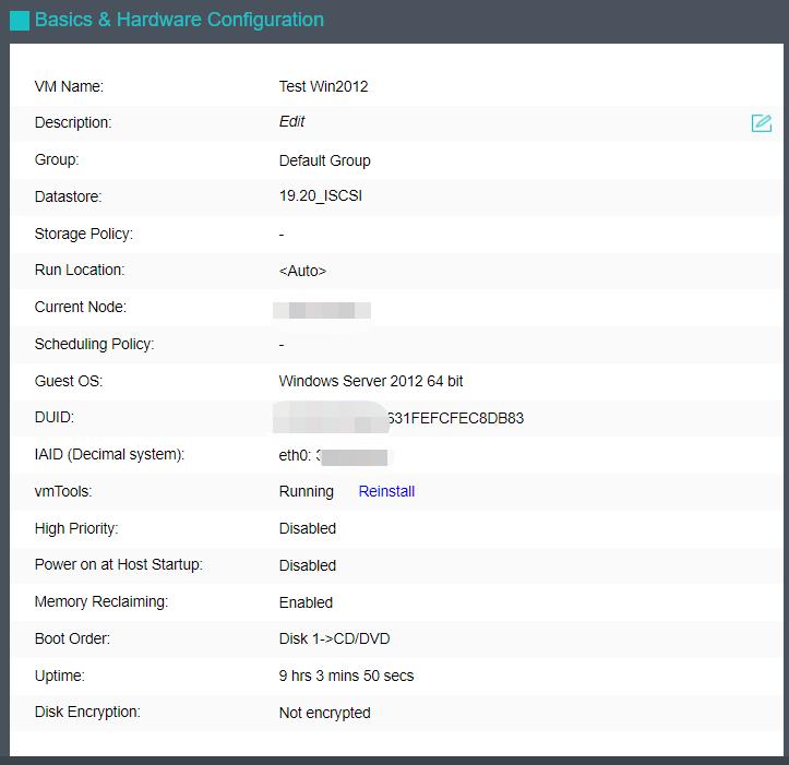
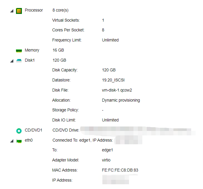
Delete Virtual Machine
Description
This section instructs the administrator to delete a virtual machine.
Precautions
The shared disk will not be deleted when the virtual machine is deleted. If you need to delete the shared disk, please go to Storage > Virtual Storage > Shared Disks to delete it manually. Refer to Chapter 7.2.14 Delete Virtual Shared Disk in this manual.
Prerequisites
The virtual machine must shut down.
Steps
- On the Compute page, click the virtual machine name in the virtual machine list, select More > Delete, and enter the delete virtual machine confirmation page.
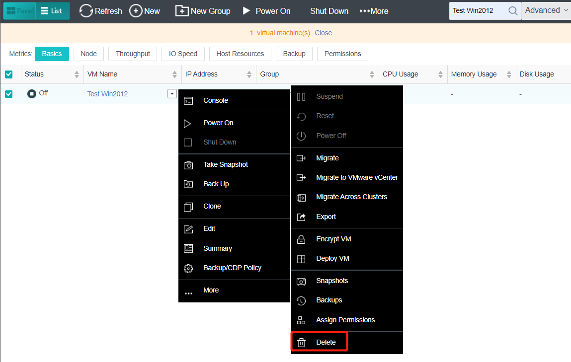
- Click Confirm to finish deleting the virtual machine.
Note:
The deleted virtual machine can be recovered in the recycle bin to prevent accidental deletion. Administrators can open the recycle bin by navigating to System > Recycle Bin.
Configuring Virtual Network
Configuring Edge Network
Concepts of Edge Network
Edge: An edge connects a physical network and a virtual network. It uses a physical interface or aggregate interface to connect to a physical network in Trunk mode.
Port group: When configuring edge, you need to specify a port group. A port group consists of more than one interface with the same configuration (such as VLAN).
Edge with Multi-Segment Port Group
Description
It allows the administrator to create an Edge for a multi-segment port group. This type of port group allows virtual machines to access multiple network segments.
Precautions
- The opposite end of the Edge interface associated with the multiple-segment port group must be configured as a trunk, and the pvid of the switch port is the pvid VLAN set by the port group associated with the physical network. This type of port group allows users to use multiple business network segments.
- The physical network supports a single interface, a dual interface for link aggregation, and four interfaces for link aggregation. Link aggregation needs to be configured in the physical network of the physical machine details, and the port of the switch also needs to be configured with the corresponding link aggregation mode.
- The pvid of the same port group is consistent with the switch.
Prerequisites
Complete switch configurations in accordance with Precautions.
Steps
- Navigate to Networking > Topology, and click Edit.

- Drag the Edge network from the network device on the left to the network topology, and then select the corresponding physical interface from the server on the right.
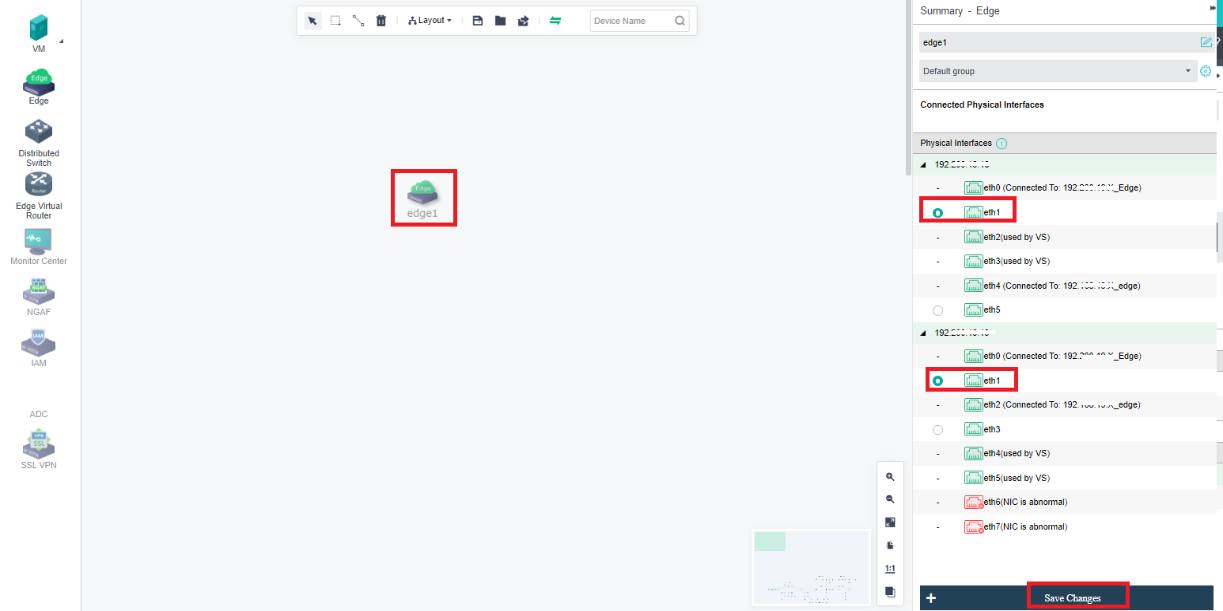
-
Click Save Changes and click Exit in the upper left corner to complete the Edge network.
-
Select the created Edge network, and select Port Group to enter the settings page.
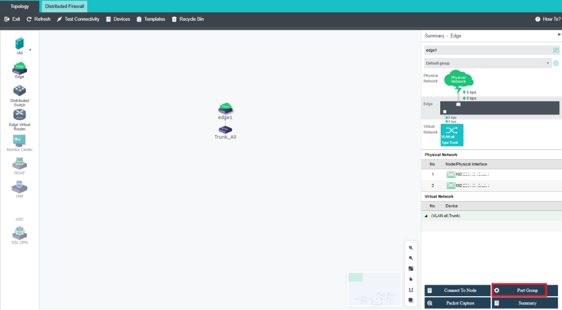
- Select Port Group and click the edit icon. (You can also add a trunk-type port group yourself).

- Configure VLAN ID and PVID VLAN. Click OK to save the configuration.

- Verify the port group created.

Creating Edge Network
Description
This allows the administrator to create a physical outlet for a single network segment port group.
Precautions
- The switch at the opposite end of the server interface associated with the physical interface of the non-multiple segment port group must be configured as access. The VLAN allowed by the switch port is the pvid VLAN set by the physical interface associated port group. This type of port group only allows users to use one service interface segment.
- The physical interface supports a single interface and link aggregation. Link aggregation needs to be configured in the physical machine’s physical network, and the switch’s port also needs to be configured with the corresponding link aggregation mode.
Note:
The pvid of the port group of the same physical interface is the same as the switch.
Prerequisites
Complete switch configurations in accordance with Precautions.
Steps
- Navigate to Networking > Topology, and click Edit.
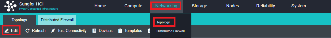
- Drag the Edge network from the network device on the left to the network topology, and then select the corresponding physical interface from the server on the right.
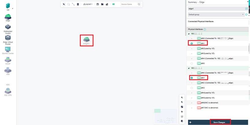
- Click Save Changes and click Exit in the upper left corner to complete the Edge network.
- Select the created Edge network, and select Port Group to enter the settings page.
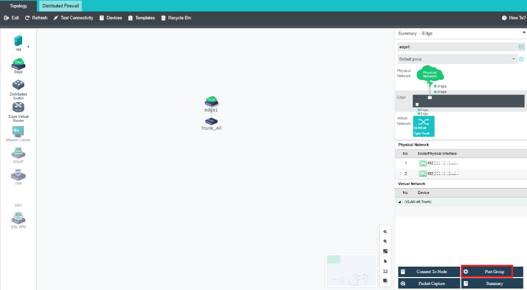
- Select Port Group and click the edit icon. (You can also add a trunk-type port group yourself).
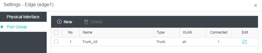
- Configure VLAN ID and PVID VLAN. Click OK to save the configuration.
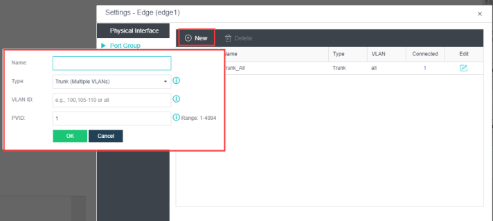
- Verify the port group created.

Edge Interface Topology
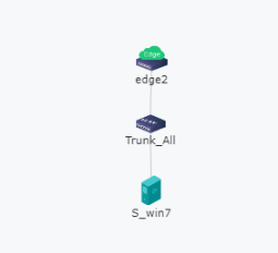
Configuration instructions
The virtual machine is directly connected to the Edge Interface. It is connected to different network segments through different port groups.
Creating a Virtual Network Device
Creating Virtual Router
Description
This section guides administrators in creating virtual routers.
Virtual routers support the following features:
- Layer 3 network port, VLAN sub-interface (support IPv4 and IPv6)
- Static routing (support IPv4 and IPv6)
- Source Address Translation (SNAT), Destination Address Translation (DNAT) (only supports IPv4)
- Policy routing (supports IPv4 and IPv6)
- Access Control
- DHCPv4 and DHCPv6
- DNS proxy
- High availability HA
- Specify the running position
Precautions
- The router can be directly connected to the edge interface port group.
- The router is connected to the Layer 2 virtual machine switch to connect to the virtual machine.
- When the router is interconnected with other Layer 3 devices, such as routers and firewalls, a Layer 2 switch must be connected in the middle.
- A single virtual router runs on a single node, enabling redundancy through failover HA.
Prerequisites
None.
Steps
- Navigate to Networking > Topology, and click Edit.
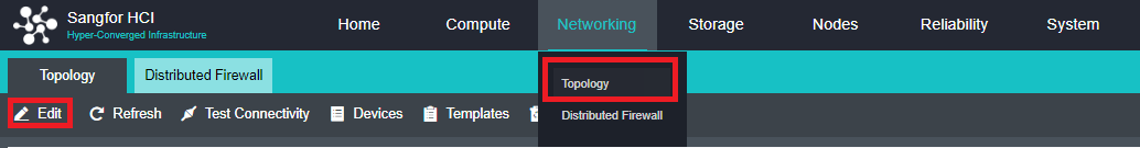
- Drag the Edge Virtual Router from the left to the network topology, and click Apply Changes.
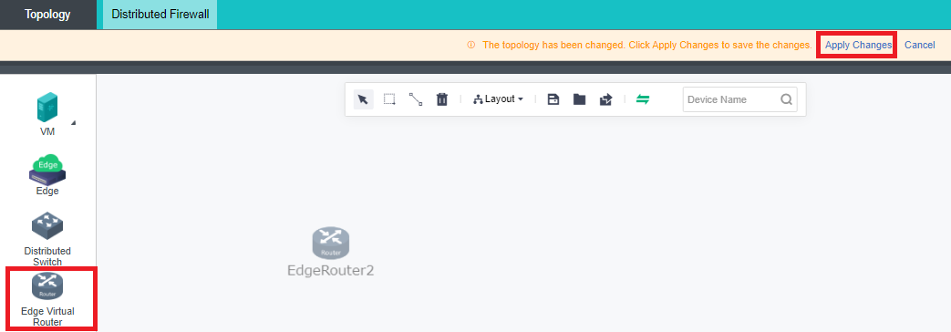
- Click Settings to enter the configuration interface of the virtual router.
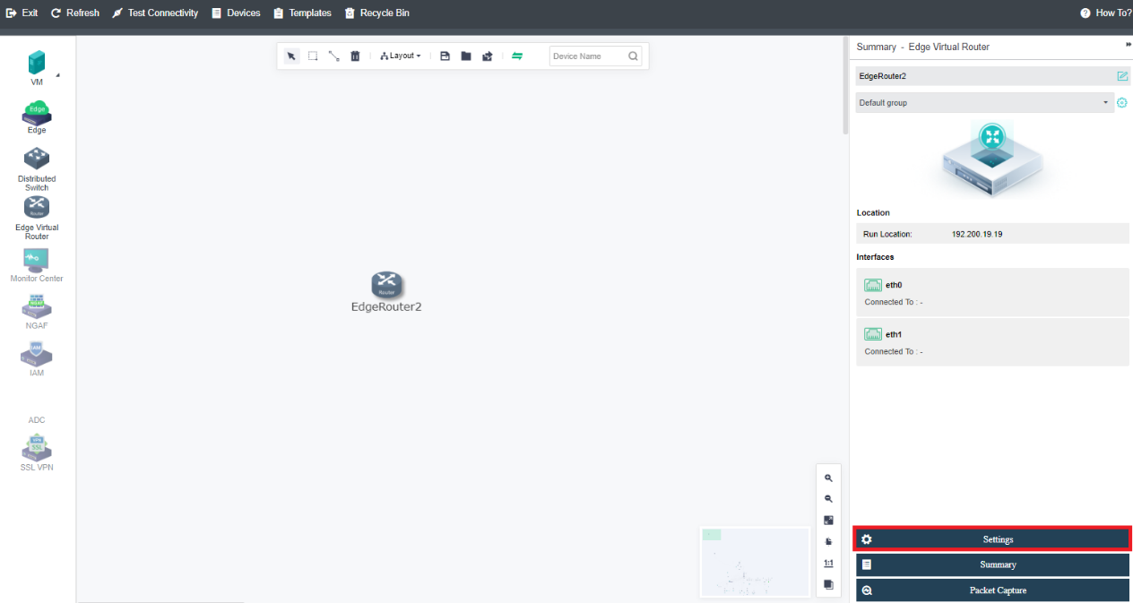
- Click New under the Interface tab to configure the network interface and VLAN subinterface. The interface IP address supports IPv4 and IPv6 addresses.
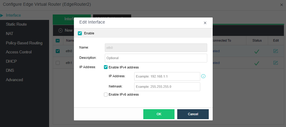
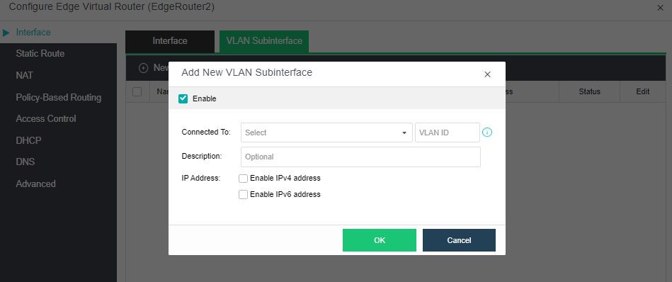
- Click New under the Static Route tab to configure a static route. Static routes support IPv4 and IPv6.
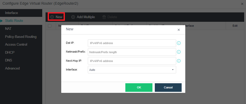
- Click New under the Source NAT tab to configure SNAT, and click New under the Destination NAT tab to configure DNAT. Source address translation and destination address translation only support IPv4 addresses.
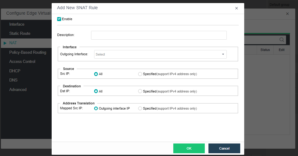
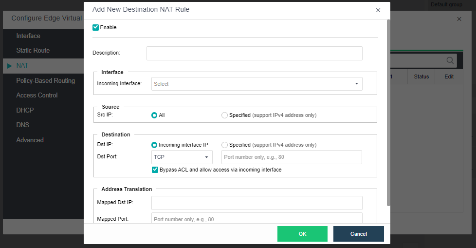
- Click New under the Policy Based Routing tab to configure PBR, which supports IPv4 and IPv6.
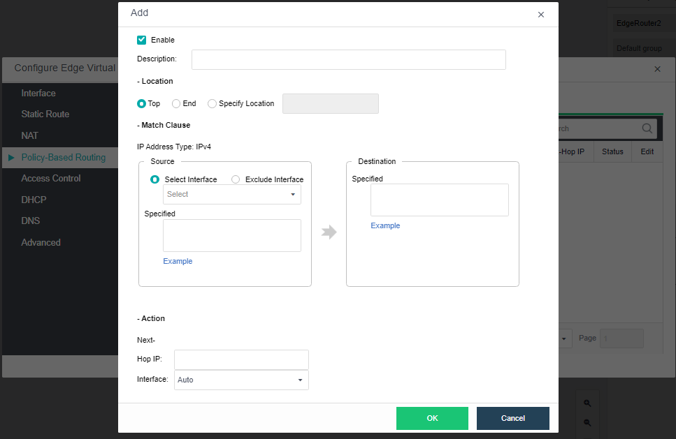
- Under the Access Control tab, click New to configure an access control policy.
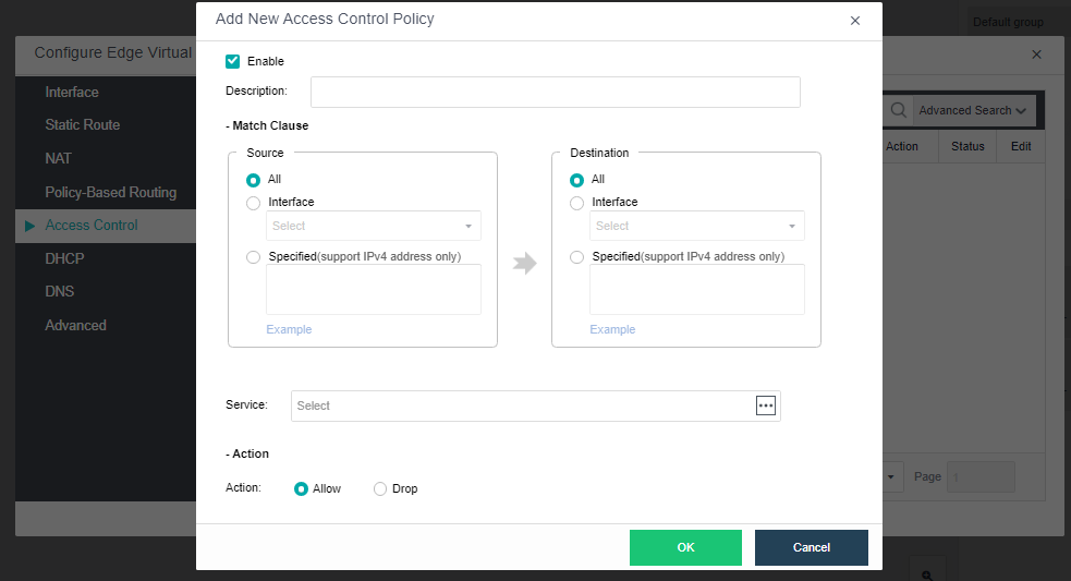
- Under the DHCP tab, click Add IP Address to configure the address range of the DHCP IP pool (both IPv4 and IPv6 are supported). You can view the currently assigned IPv4 address information in DHCPv4. In DHCPv6, you can view the currently assigned IPv6 address information.
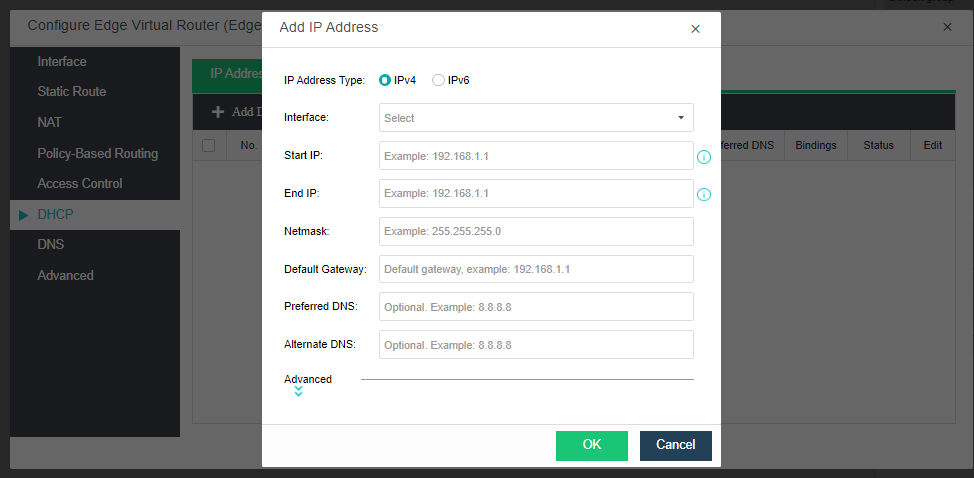
- Under the DNS tab, check the Enable DNS proxy checkbox and click OK to configure the Preferred DNS and Alternate DNS.
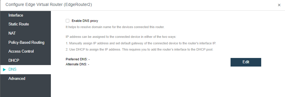
- Under the Advanced tab, configure the HA and running location of the virtual router.
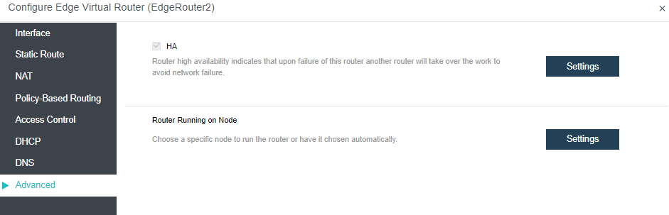
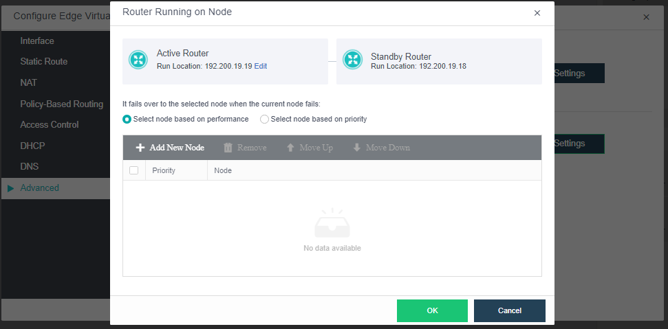
-
HA: If HA is enabled, a second router will be built on another node and synchronize data in real-time. If one node fails, the second router will take over seamlessly. However, synchronizing data between the two routers will consume extra network bandwidth.
-
Router Running on Node: By default, the node where the router runs is automatically selected according to the settings on the following page. You can change the current node running the router as per your need.
Configuring Virtual Switch
Description
This section guides administrators in creating a distributed virtual switch.
The distributed virtual switch supports broadcast storm prevention and can set the flow and packet rate threshold.
Precautions
- Distributed virtual switches are all Layer 2 switches.
- Usually it is directly connected to Layer 3 devices such as virtual routers.
Prerequisites
None.
Steps
- Navigate to Networking > Topology, and click Edit.

-
Drag the virtual switch from the network device on the left to the network topology, click Apply Changes, and click Exit in the upper left corner to complete the virtual switch creation.
-
Click the virtual switch, click Advanced in the selection box on the right to configure broadcast storm prevention parameters, and click Save.

-
Flow rate threshold: When a broadcast storm occurs on the switch, you can limit the switch to forward the network flow rate or disconnect some interfaces to block the storm.
-
Packet rate threshold: When the switch has a broadcast storm, you can limit the switch forwarding and sending rate or disconnect some interfaces to block the storm.
Topology of Virtual Switch Router
Configuration instructions
-
As a Layer 2 device, the switch connects the virtual machine and the router and configures the service network IP for routing to connect with the external service gateway.
-
Configure routing and NAT policies on the router to enable internal virtual machines to communicate with the outside world.
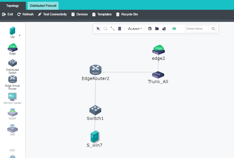
Creating other NFV Devices
Description
This section guides administrators to create NFV devices (example: vAF).
Precautions
NFV appliance includes Sangfor Next-Generation Firewall (vAF), Application Delivery (vAD), Internet Access Management (vIAM), SSL VPN, and WAN Optimization (vWOC), which are created similarly.
Prerequisites
- The vAF licensing has been obtained.
- The vAC template related to Sangfor NFV has been uploaded.
Steps
- Navigate to Networking > Topology, and click Edit.
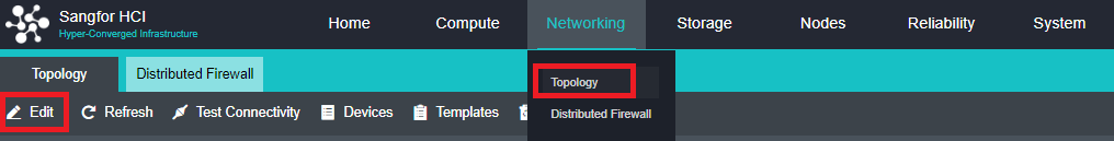
- Drag the vAF from the left to the network topology, click Apply Changes, and click Exit in the upper left corner to complete the creation.
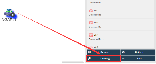
- The device is automatically turned on after licensing. You can log in to the web for management.

Configuring Traffic Mirroring
Description
In the operation and maintenance scenario, the production virtual machines’ network traffic must mirror the security auditing device to achieve traffic filtering and monitoring. Sangfor HCI supports replicating and forwarding virtual machines/network traffic to the egress interface to mirror external devices. It requires configuring traffic mirroring on the intermediate switch.
Precautions
- A mirror source policy object can select up to 1024 network interfaces.
- The mirror target object can only select one virtual machine or network device network interface.
- If a virtual machine/network device network interface or physical node edge interface is used as a mirror source object, it can only belong to one traffic mirroring policy; if it is used as a mirror target object, it can belong to multiple traffic mirroring policies.
- Traffic mirroring from the physical network to the virtual network is not supported.
- As the number of policies increases, the latency of production network traffic increases, and the throughput decrease. It is recommended to configure less than 100 policies.
- The virtual machine referenced by the traffic mirroring supports intra-cluster migration, and the traffic mirroring would still take effect after the migration.
- Support configuring traffic mirror for separate physical egress interface. In the scenario of mirroring virtual network traffic to an external device, the mirrored traffic utilizes the edge interface; when mirroring across nodes in a cluster, the mirrored traffic utilizes the VXLAN interface. Planning an independent physical interface for traffic mirroring and forwarding is recommended.
- When the traffic mirroring is through the physical edge interface, a VLAN must be configured, and the VLAN must be the same as the VLAN allowed on the physical switch (truck port) connected to the physical egress interface. The mirrored traffic cannot include the traffic of this VLAN.
- When the edge-connected interface to the physical egress interface is used in the mirroring policy, when the edge-connected interface to the physical egress is modified, the corresponding physical egress interface in the traffic mirroring policy is also changed.
- Cross-resource pool mirroring is only supported in connected domain scenarios.
- Even traffic intercepted by DFW and traffic restricted by QoS will be captured and forwarded by traffic mirroring.
- When the network interface is multiplexed, and the network interface is used as the mirror source, only edge traffic is captured.
Prerequisites
N/A.
Steps
- Navigate to Networking, click Traffic Mirroring, and then click New to create the traffic mirroring policy.
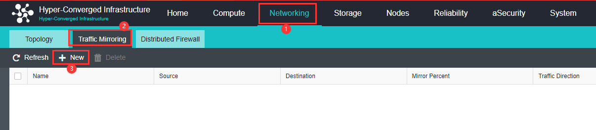
- Sangfor HCI supports configuring three traffic mirroring policies: VM Interface, NFV Device Interface, and Edge-connected Interface.
-
Mirror Source:
VM Interface: Specify the network interface of the virtual machine/network device.
NFV Device Interface: specify the virtual machine/network device network Interface.
Edge-Connected Interface: Specify the edge interface of the physical node.
-
Mirror Target:
VM Interface: Specify the network interface of the virtual machine/network device.NFV Device Interface: specify the virtual machine/network device network Interface.
Edge-Connected Interface: Specify the edge interface of the physical node.
-
VLAN ID:
VM Interface: not required.NFV Device Interface: Specifies the VLAN ID tagged in the mirrored packets.
Edge-Connected Interface: Specifies the VLAN ID tagged in the mirrored packets.
-
Mirror Percent:
Percentage of the traffic to be mirrored. By default, it is 100%, which means all the traffic will be mirrored. -
Traffic Direction:
The direction of the source object’s traffic.
All: Mirroring the traffic received and sent by the source object.
Inbound: Only mirroring the traffic received by the source object.
Outbound: Only mirroring the traffic sent by the source object.
- Policy Status:
Check Enabled to enable the policy to take effect.
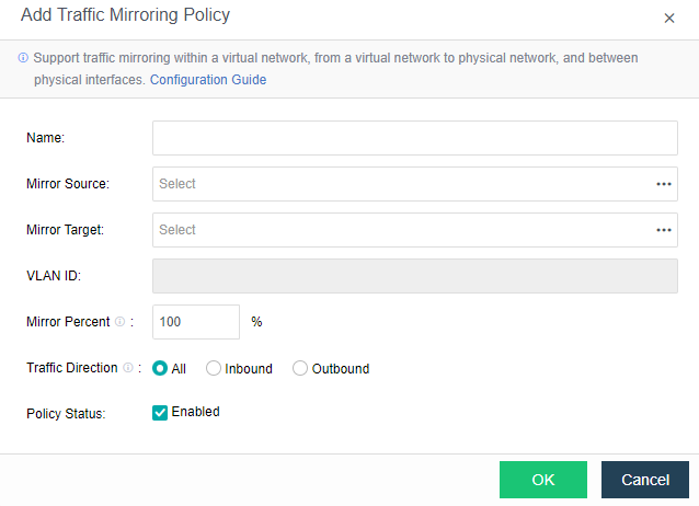
- After the policy configuration is complete, the network traffic at the source can be monitored on the destination device.
Configuring Distributed Firewall
Description
This section guides administrators in creating a distributed firewall.
Precautions
- Distributed firewall is for protection below layer 4.
- When SCP manages HCI, but no connectivity zone is created, the original policy of the distributed firewall remains unchanged but is not displayed.
- The distributed firewall function is unavailable when the SCP manages the HCI and a connected domain is created.
- When HCI is upgraded from an earlier version to version 670, the original distributed firewall policy will be placed in the default policy.
Prerequisites
Purchase the aNet license.
Steps
- Click Networking > Distributed Firewall to enter the firewall configuration interface status, and click Create to enter the Create Policy page.
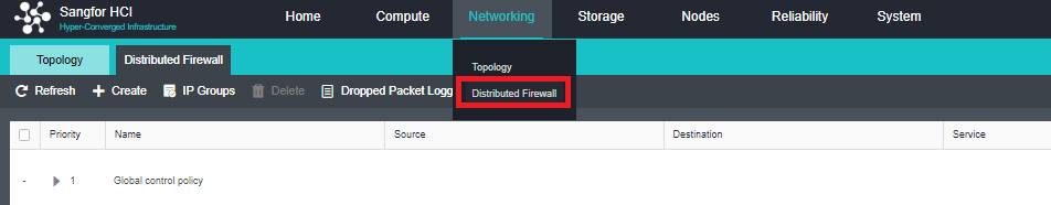
- Configure the policy name and priority, configure the rule’s source and destination IP or virtual machine, select the service or custom service protocol and interface, select the rule action in the policy, enable the rule, and click OK to complete the configuration.
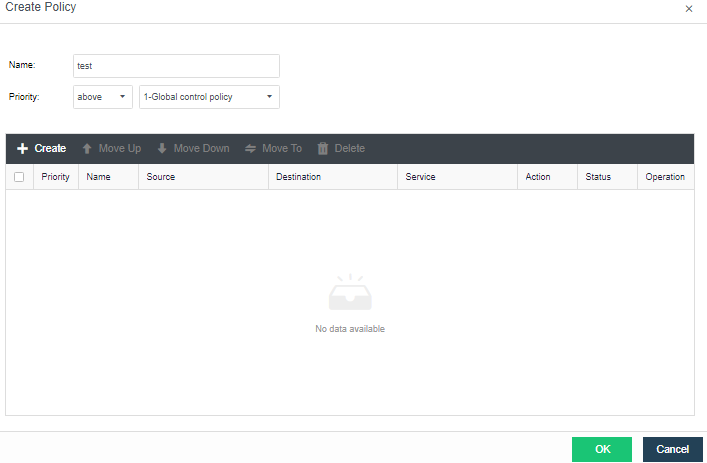
- Select the rule action in the policy, enable the rule, and click OK to complete the configuration.
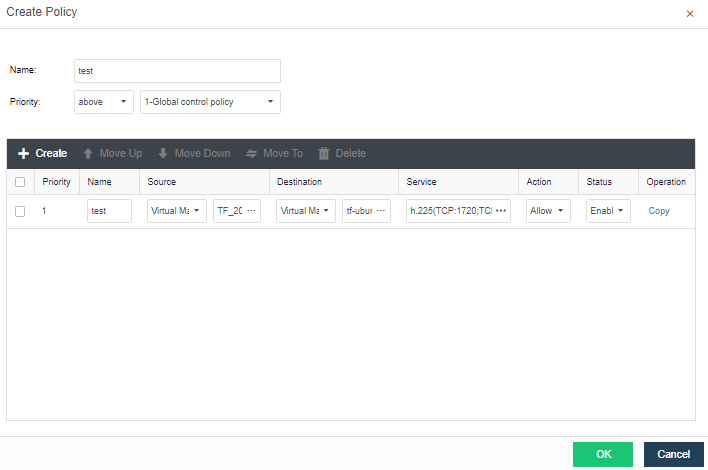
-
Policy Name: Define the name of the firewall policy.
-
Policy Priority: Define the priority order of the created policy among all policies.
-
Priority: Define the priority of the rules in the policy. The lower the value, the higher the priority.
Network Insight
Description
Network insight (aNI, Advanced Network Insight) achieves the automation of collecting and sorting virtual machine access relationships, automatically adding and displaying new assets, and synchronizing asset status on time. From a business perspective, it provides an intuitive and clear access relationship topology diagram and access details between virtual machines. It is convenient for optimizing policy configuration, discovering business access risks, and reducing risky port exposure.
Precautions
- The number of access relationship records on a single node exceeds the specification limit, which will cause random packet loss of overloaded virtual machines and loss of access relationship data. Specifications are as follows:
| Specification | Cores | RAM | Storage | Total number of virtual machines |
|---|---|---|---|---|
| Small | 8 | 16GB | 500GB | 100 |
| Medium | 32 | 64GB | 1T | 1000 |
| Large | 64 | 128GB | 1.5T | 3000 |
- Currently, the collection of traffic between virtual routers/virtual switches and NFV is not supported.
- Currently, the collection of traffic for IPv6 is not supported.
- When HCI changes the virtual machine’s IP address, the network insight’s traffic update will be delayed, and the latest update time will be 5 minutes.
- The network insight licensing is integrated with aNET, and there is no need to activate the license separately.
- The aNI virtual machine password is restricted to be changed once every 3 months.
- The interface does not support expanding groups of more than 100 virtual machines.
- Only the traffic passing through the DWF is collected (the DWF is enabled by default in HCI 6.7.0 version), and the traffic not passing through the DWF cannot be collected and reported. (The traffic between virtual routers, virtual switches, and NFV are not collected).
Prerequisites
N/A
Steps
- Navigate to Networking > Network Management and select Network Insight to enter the Network Insight page. Click the Get Started button and follow the instruction for network insight deployment.
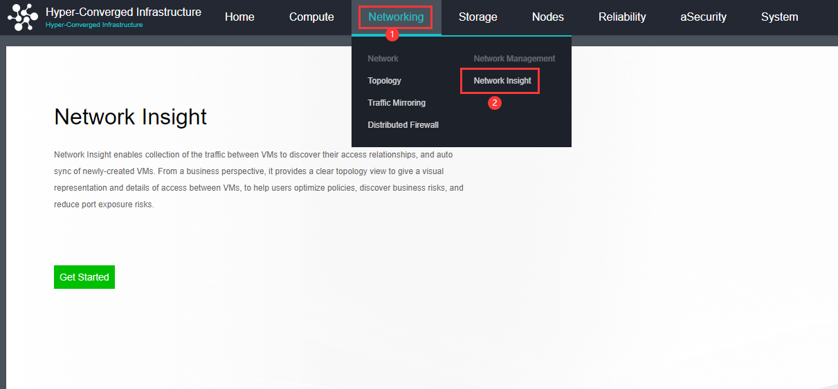
- Click the Deploy Now button to enter the import virtual machine page. Follow the wizard prompts to import the vma file of the aNI virtual machine, and select the group, datastore, storage policy, and run location.
Caution:
After the virtual machine is imported, please view the wizard shown in the figure below, and edit the parameters of the template virtual machine according to the number of existing virtual machines and according to the small, medium, and large specifications. The storage capacity is mainly used to store all the streaming data of virtual machines with access relationships on the platform within 30 days.
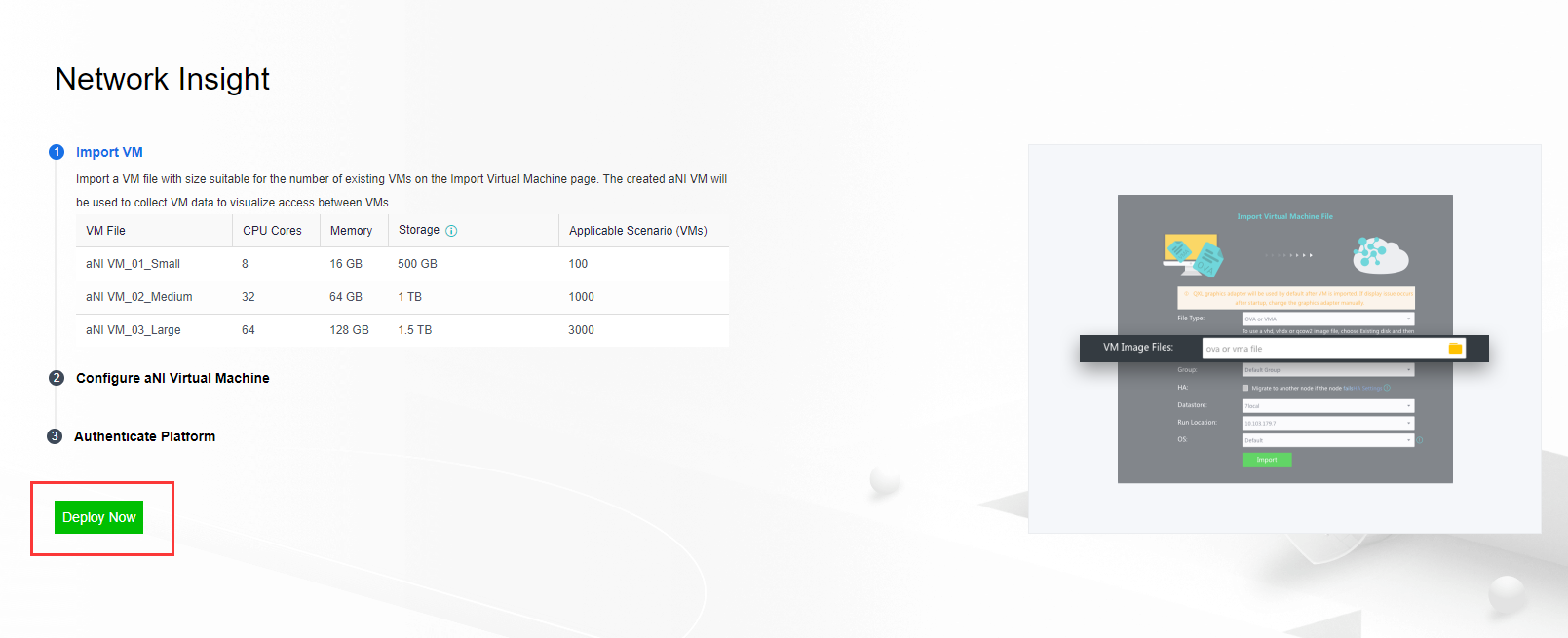
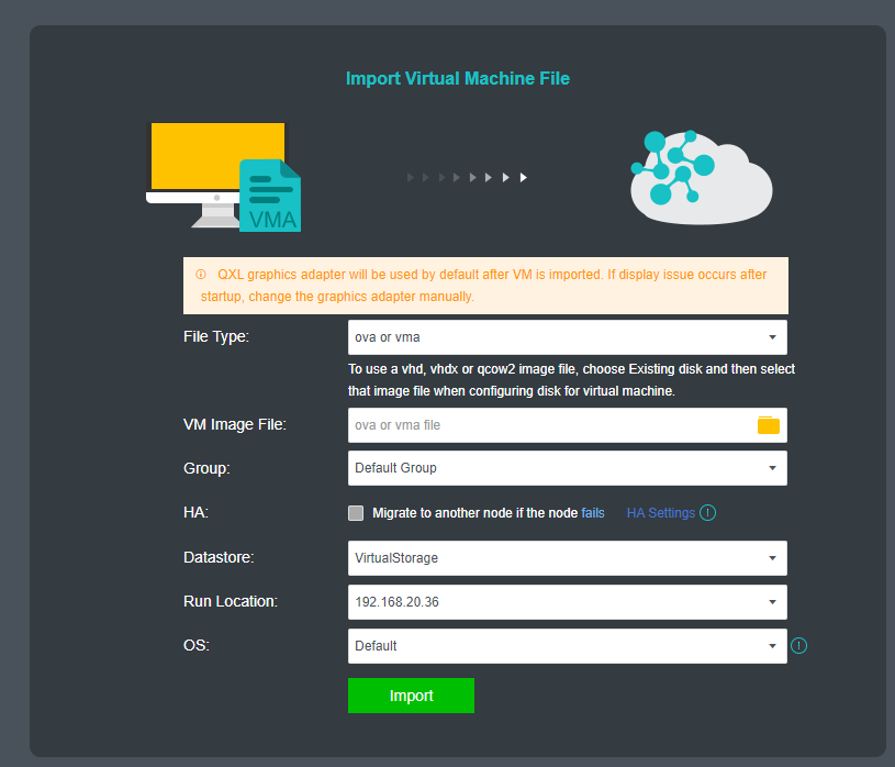
- After the virtual machine has been successfully imported, Edit the virtual machine, enable its network interface, and connect to the edge interface, then check the Enable IPv4 address checkbox and configure the IP address as the management interface of the network insight. (It is required to ensure the communication between the HCI management interface is reachable, and it is recommended to be on the same network segment as the HCI management interface).
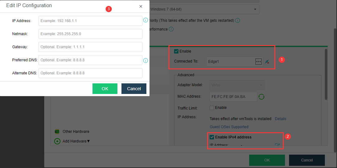
- Enable the Correlated Security Service. Otherwise, the network insight might be unreachable.
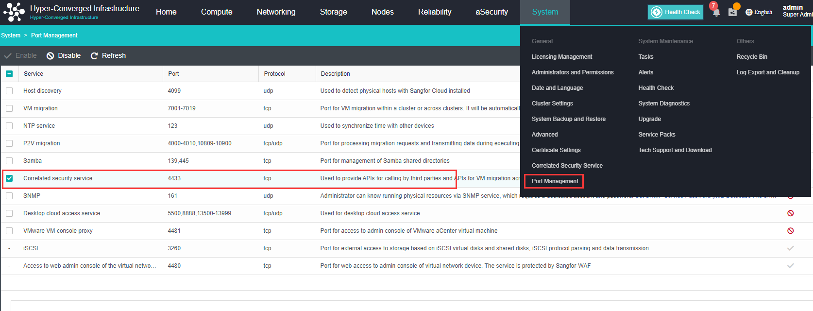
- Power on the aNI virtual machine, enter its console, and configure the platform authentication.
Step 1. Input the aNI login credentials to log in.
Note:
Changing the password for the first login is required, and there are only five attempts for the wrong password retry. If you enter the wrong password five times, the account will be locked for 5 minutes, and you can enter retry after 5 minutes.
The default password is Sfcsec@123. The password policy is as follows:
- Password length should be 8 to 64 characters and cannot contain the username.
- Password must contain uppercase letters, lowercase letters, digits, and special characters. such as ~`@#%&<>"’,;_-^$.*+?=!:|{}()[]/ .
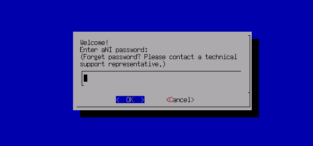
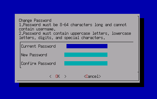
Step 2. After the password change, it is required to log in again. Select Platform Authentication and select HCI as the platform type.
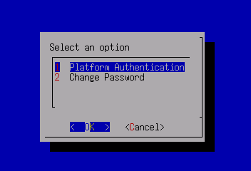
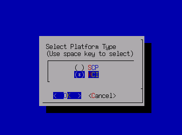
Step 3. Input the cluster IP, username, and password to authenticate.
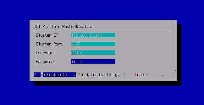

- After the platform authentication is successful, enter the Network Insight page again, and click the Get Started button to enter the network insight page.
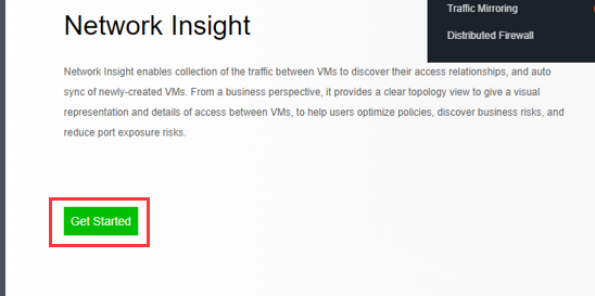
- On the insight page, you can see the access status of all virtual machines on the platform. Advanced filtering in the upper right corner supports interface filtering according to different conditions. At the same time, it supports searching according to the perspective of virtual machines and virtual machine groups to quickly locate the virtual machines or groups that need to be viewed.
- Access Statuses filter: All Access Statuses, Allowed, Denied and No Policy Matched.
- Day filter: Last 30 days, Last 7 days, Last 3 days, and Today.
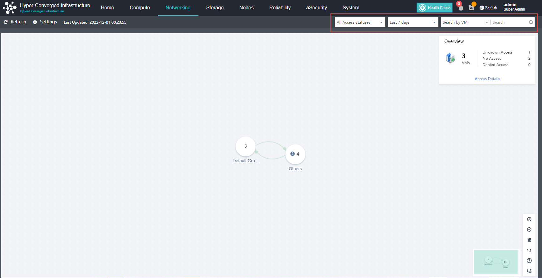
- Select a group to enter the virtual machine group display page. The overview in the upper right corner displays the current group’s virtual machine access relationship information, including the total number of virtual machines, unknown access, no access, and denied access. Click the zoom-out button, and it will return to the initial view.
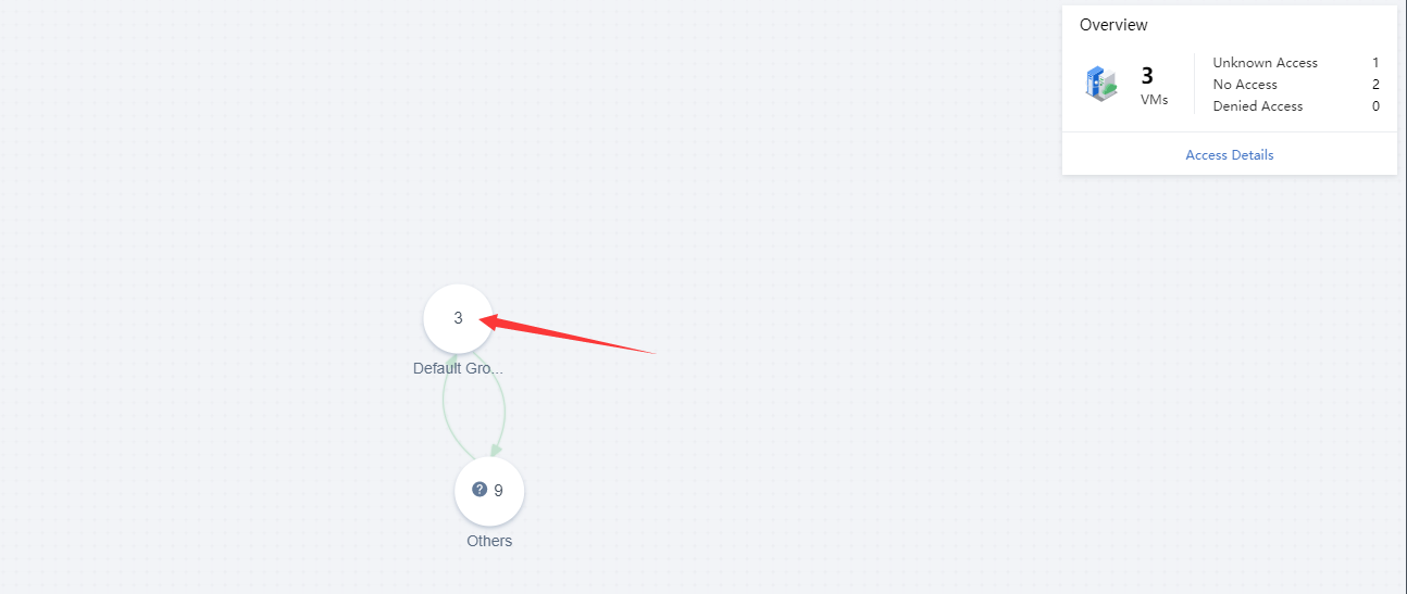
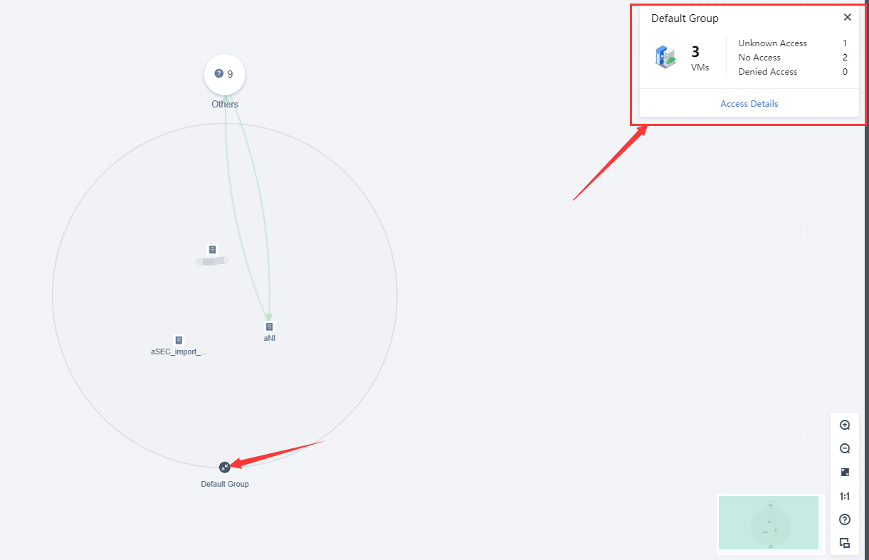
- Click the Access Details button to enter the details page. Click the View Details to view every recorded access entry, including src object, src IP, dst object, destination IP and service.
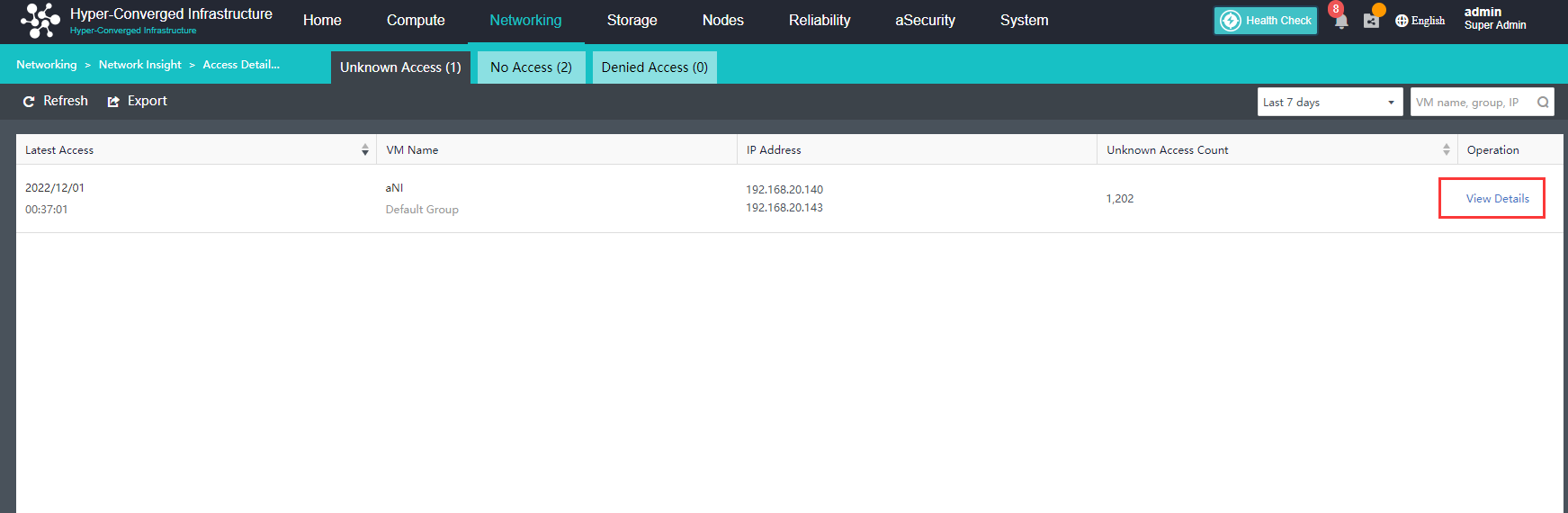
- Click the View Policies button, and it will redirect to the Distributed Firewall page to add, delete, modify, and check on the policy.
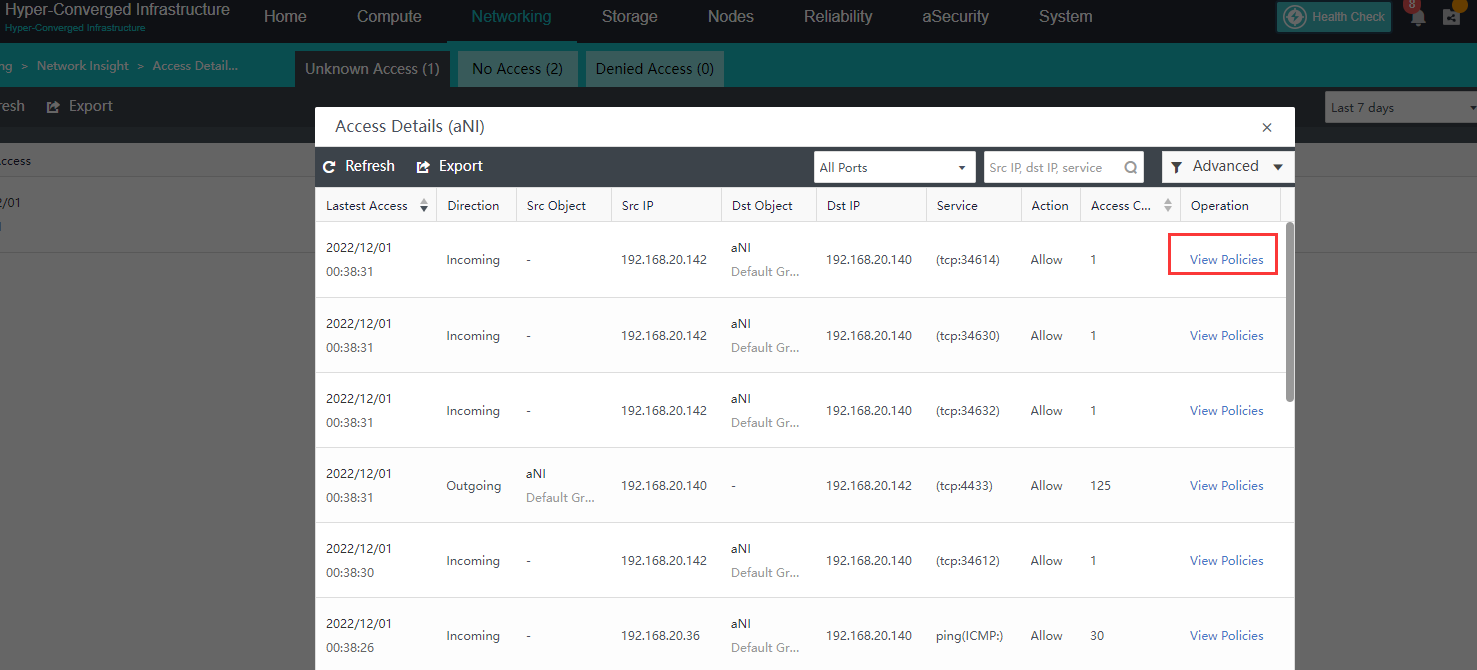
- Sangfor HCI also supports related settings for the network insight service. Click the Settings button to go to the setting page. It supports enabling or disabling the network insight feature and aNI version upgrade.
Note:
After the network insight feature is disabled, this feature can no longer be used. You need to redeploy to enable the feature again.
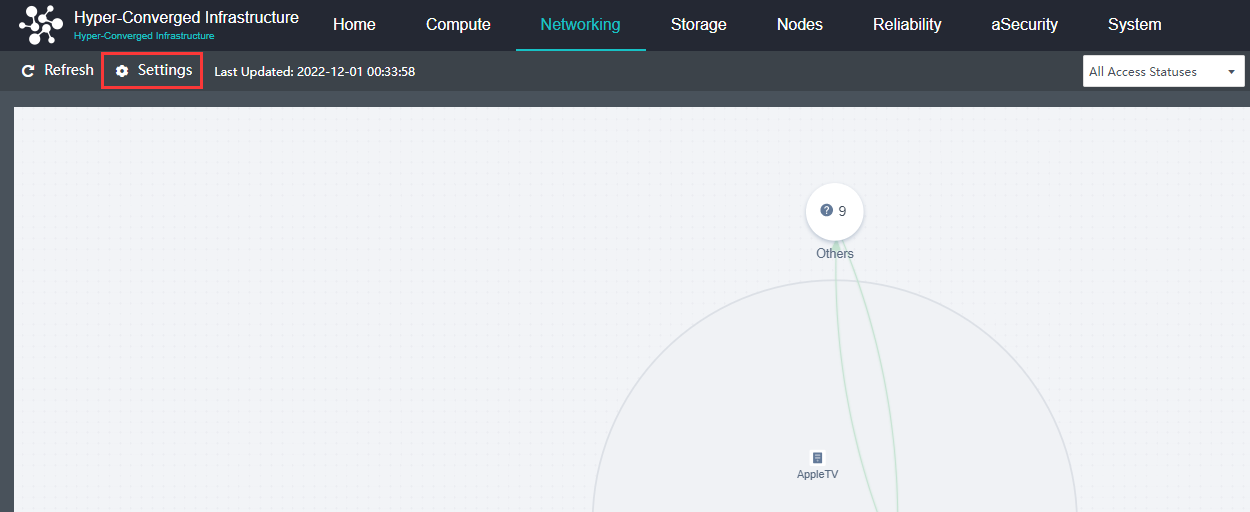
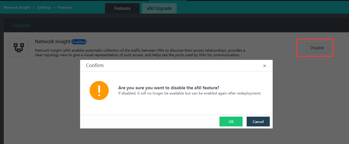
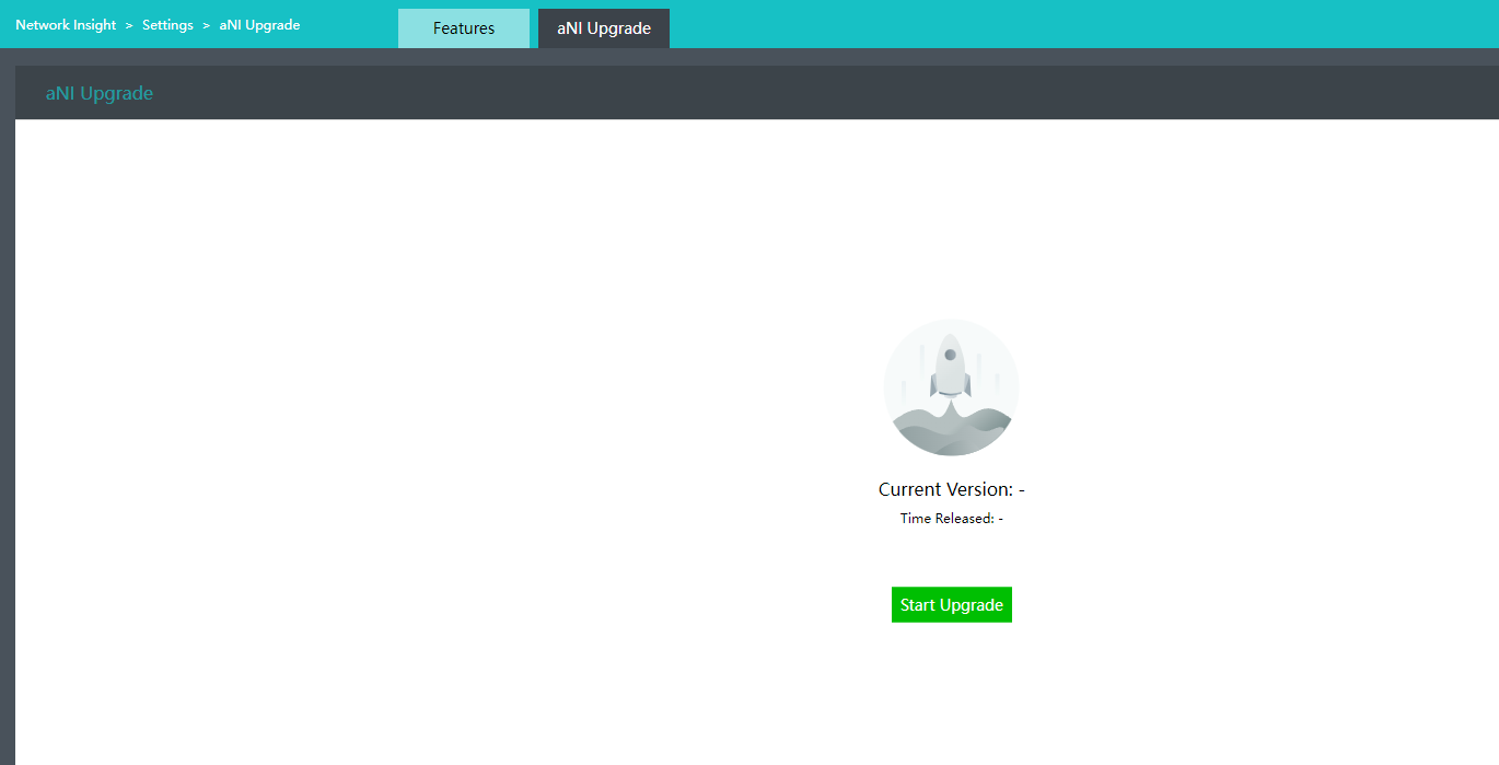
Manage NFV devices
Description
NFV starts, shuts down, powers off, migrates, deletes operations, and supports the simultaneous operation of multiple devices.
Precautions
- The name of the vAF virtual machine contains the word server, and the single sign-on will be intercepted by vAF and recognized as SQL injection. The name of the vAF virtual machine should not have the word server, and it should be changed to another name.
- Opening vSSL VPN and vAF console at the same time will affect each other, failing of single sign-on. If you need to open at the same time, please use different browsers to open vAF and SSL VPN for single sign-on.
- Do not deploy multiple vAFs in the transparent mode in a broadcast domain, which will cause MAC address conflict.
- Try not to pass the vAF for east-west traffic. The reason is that the east-west traffic will be relatively large, and the performance of vAF is much lower than that of physical AF. Once a performance bottleneck is encountered, the network will slow down. There is no need to perform Layer 7 cleaning for east-west traffic, and the distributed firewall of aNET can meet the requirements. It is recommended to deploy vAF at the egress of north-south traffic.
- After the cluster deployment is completed, if NFV is used (such as vAD, vAF, etc.), it is not recommended to modify the CPU cores consumed by network forwarding and memory consumed by network forwarding in the host. In this case, the network cables of all virtual network devices must be manually deleted and reconnected to recover.
- The clone deployment of NFV is not supported, and a new deployment needs to be added from the Network Topology.
Prerequisites
None.
Steps
-
On the Networking page, click Devices to enter the virtual network device management page.
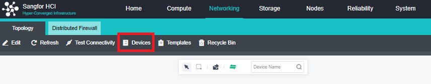
-
Check one or more NFV devices to be managed, and then click the desired operation.
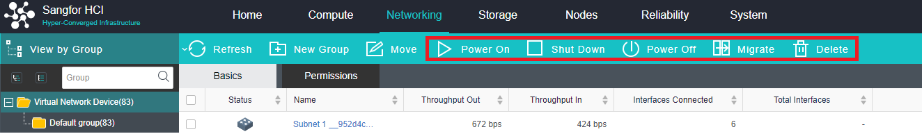
Storage Configuration Guide
View Storage Status
Description
You can view the status, usage, real-time status, performance status, alarm log, and task execution status of all storage by viewing the storage status.
Precautions
None.
Prerequisites
None.
Steps
- In Storage, you can view the Summary page. In Status, you can see the running status of all storage. If there is an abnormality, you can directly click on the number on the page to locate the abnormal storage.
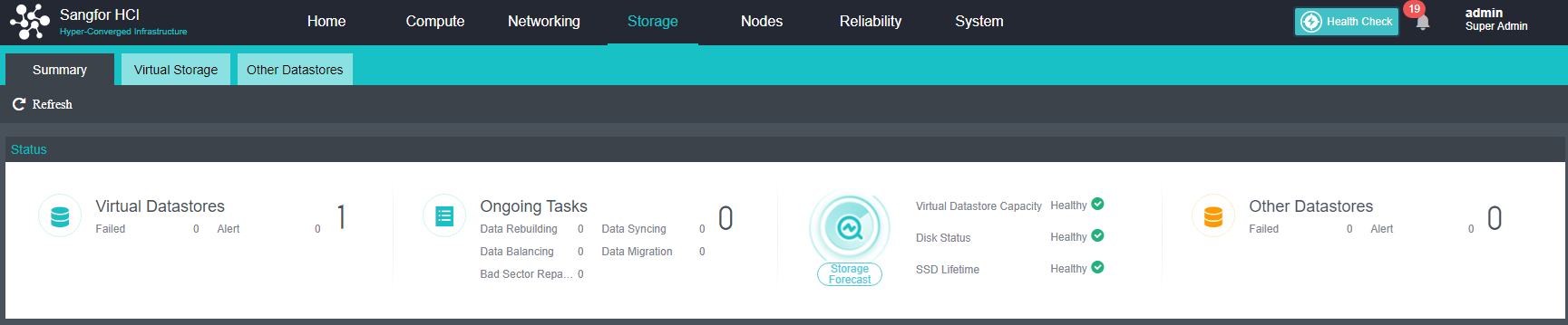
- In Virtual Datastore Status, you can see the current total capacity, used capacity, and remaining capacity of the virtual storage. Select the corresponding time range to view the IOPS, IO speed, IO latency, and node hit rate in this period.
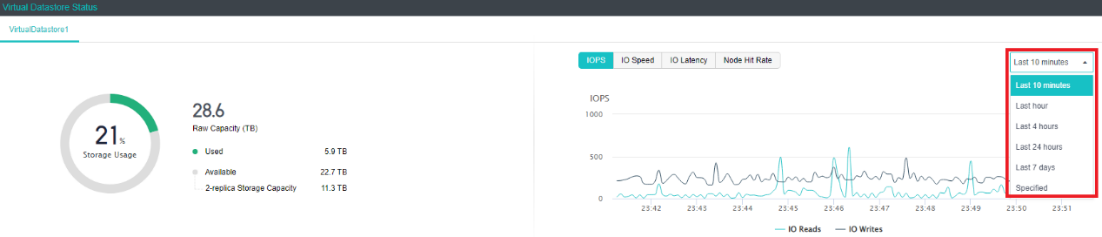
- IOPS shows the number of virtual storage reads and writes per second, corresponding to the industry term IOPS value. It shows the trend of concurrent IO times of virtual storage, reflecting the random IO capability of virtual storage.
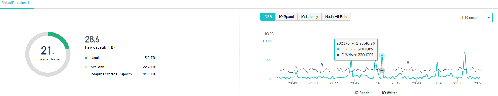
- IO Speed shows the number of bytes read and written per second of virtual storage, read xxx MB and write xx MB per second, and shows the concurrent IO throughput of virtual storage. The IO speed trend can reflect virtual storage. Sequential IO capability.
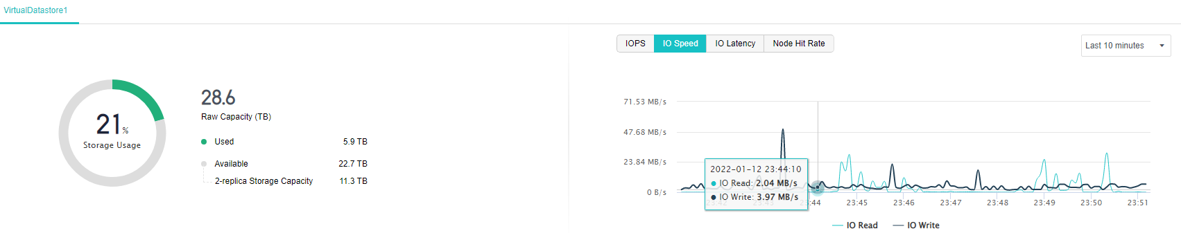
- IO Latency shows the average time required for each reading and writing of virtual storage. The IO load of the storage can be seen from the IO latency trend. If the IO latency increases, IO requests are already queued. Performance starts to fall short. Usually, the average IO latency is lower than 30ms, which means that the load is very light, and it is normal if it is lower than 60ms.
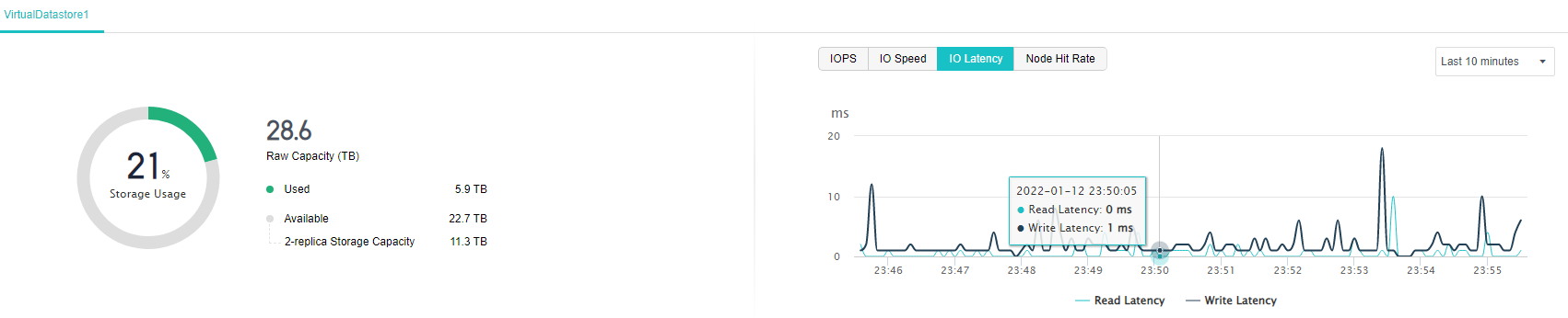
- Node Hit Rate displays the average cache hit rate of the node since it was powered on. The histogram can visually compare the difference in the hit rate of different nodes.
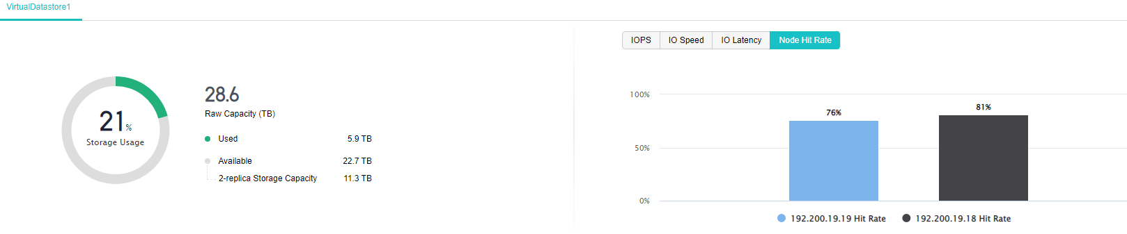
- In Realtime Status of Other Storage, you can see the total capacity of other storage, usage, read speed, write speed, the number of virtual machines stored on the storage, and the number of running virtual machines.
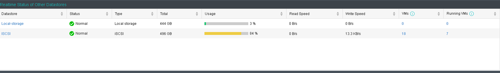
- In Unread Alerts, you can view HCI alert information, and in Task Status, you can view the tasks currently being executed by the HCI cluster. These two items can be viewed separately from the page.
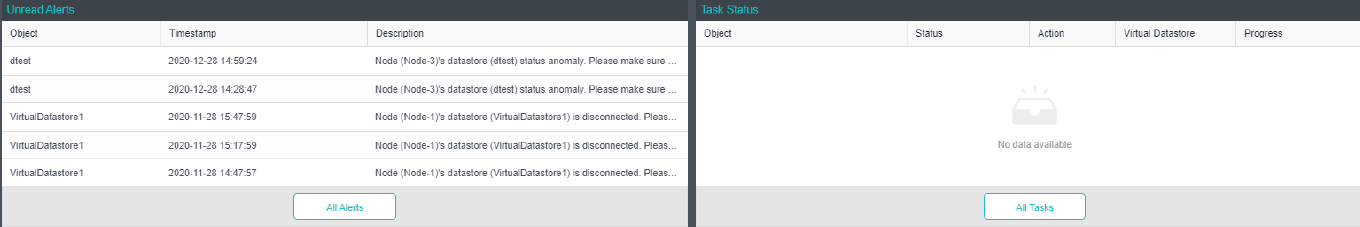
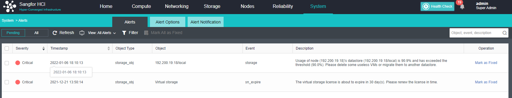
Virtual Storage Configuration Guide
Viewing Virtual Storage Status
Description
It is mainly used to determine the storage load by checking the IO read and write operations of the storage.
Precautions
None.
Prerequisites
None.
Steps
- Select the storage you want to view in Storage, and click the name to view the details.
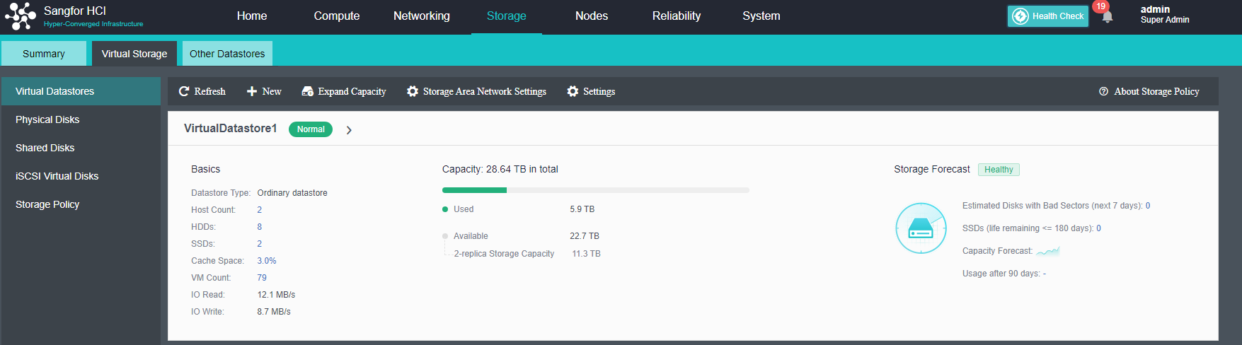
- You can see detailed information on the virtual datastore on the details page, including capacity, fault domain, node information, and running status. The running status includes IO read and write times and IO read and write speeds. When the card is installed, you can view information such as IO read/write times, and IO read/write speed in the virtual machine datastore to assist in troubleshooting.
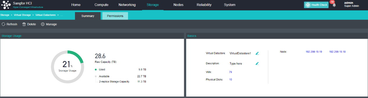
- Select the corresponding node in Nodes, and click Summary to view the node storage information.

- You can see running parameter information, traffic monitoring information, and basic hardware configuration information in the node details.
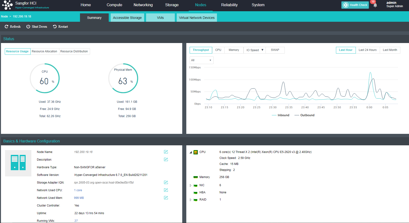
Creating Storage
Create Ordinary Datastore
Description
HCI supports multiple volume management. Common volumes and stretched volumes can exist in a cluster at the same time. Multiple virtual datastore can be created in a HCI cluster. Multi-volume can be formed by host or disk. Units and volumes are physically and logically isolated, but for virtual machines, volumes can be selected and migrated, and they can also meet the heterogeneous hardware requirements of different services in the cluster. The following operations are the procedure for adding normal volumes.
A host-based multi-volume requires at least six hosts, three hosts for a volume, and the other three for a volume. Three or more hosts can divide multiple volumes for multi-volume based on disks. Therefore, a single host can create an all-flash volume based on creating a mixed volume, which will require high disk performance. All services run on all-flash volumes to improve disk usage. Host multi-volume and disk multi-volume methods can coexist on an HCI cluster.
As an example, the supported group multi-volume mode for three hosts is shown in the figure.
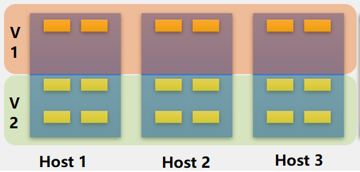
Precautions
-
The newly added volume will be formatted when it is created. Before adding, please make sure that there is no data that needs to be preserved on the disk used to add the new volume.
-
A cluster is allowed to have a maximum of six virtual datastores, of which a maximum of one stretched volume is allowed.
-
A volume consists of hard disks on at least three hosts, and a host can be divided into two volumes at most.
-
Virtual storage does not support a single copy. When a single copy is used, the virtual storage is not redundant, and there is a risk of data loss.
-
Two hosts do not support data balancing.
-
Striping is not supported for virtual machines on two hosts.
-
Virtual storage is a full HDD deployment and does not support upgrades or new deployments.
-
If the capacity of three hosts is too large, the deployment of virtual storage will be limited. It is required that the capacity of one host cannot exceed the sum of the capacities of the other hosts. For example, host A is 1TB, host B is 1TB, and host C is 5TB. Deployment is not supported.
-
A host spanned by one volume cannot belong to two other volumes.
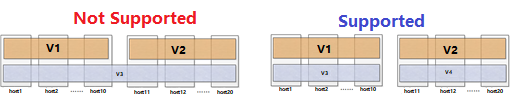
-
Stretched clusters do not support multiple volumes. As shown in the figure below, a host cannot belong to both extended and normal volumes.
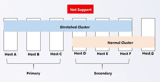
-
All-flash volumes (compression) do not support hard disk volumes but only host volumes.
-
A single host in an ordinary volume has at least one SSD, and a single host in an all-flash volume has at least two SSDs.
Prerequisites
- To set up multiple volumes, each volume requires at least three hosts.
- At least three hosts are required to form multiple disk volumes.
- The expansion host’s management interface, storage interface, overlay network interface, and service interface have been connected to the network.
Steps
Creating Storage Volume
- Navigate to Nodes and click Add New Node.
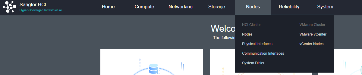

- Select the node to be added. If the node to be added is not in the list, click + to add it.
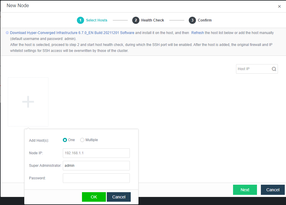
-
Adding a host will delete the firewall configuration of the added host. Click OK.
-
If it is detected that the MTU of the overlay network interface is inconsistent, reconfigure it, and check the Enable high-performance mode checkbox.
-
After adding a node successfully, configure the communication interface. Then, the new node will be visible under Home.
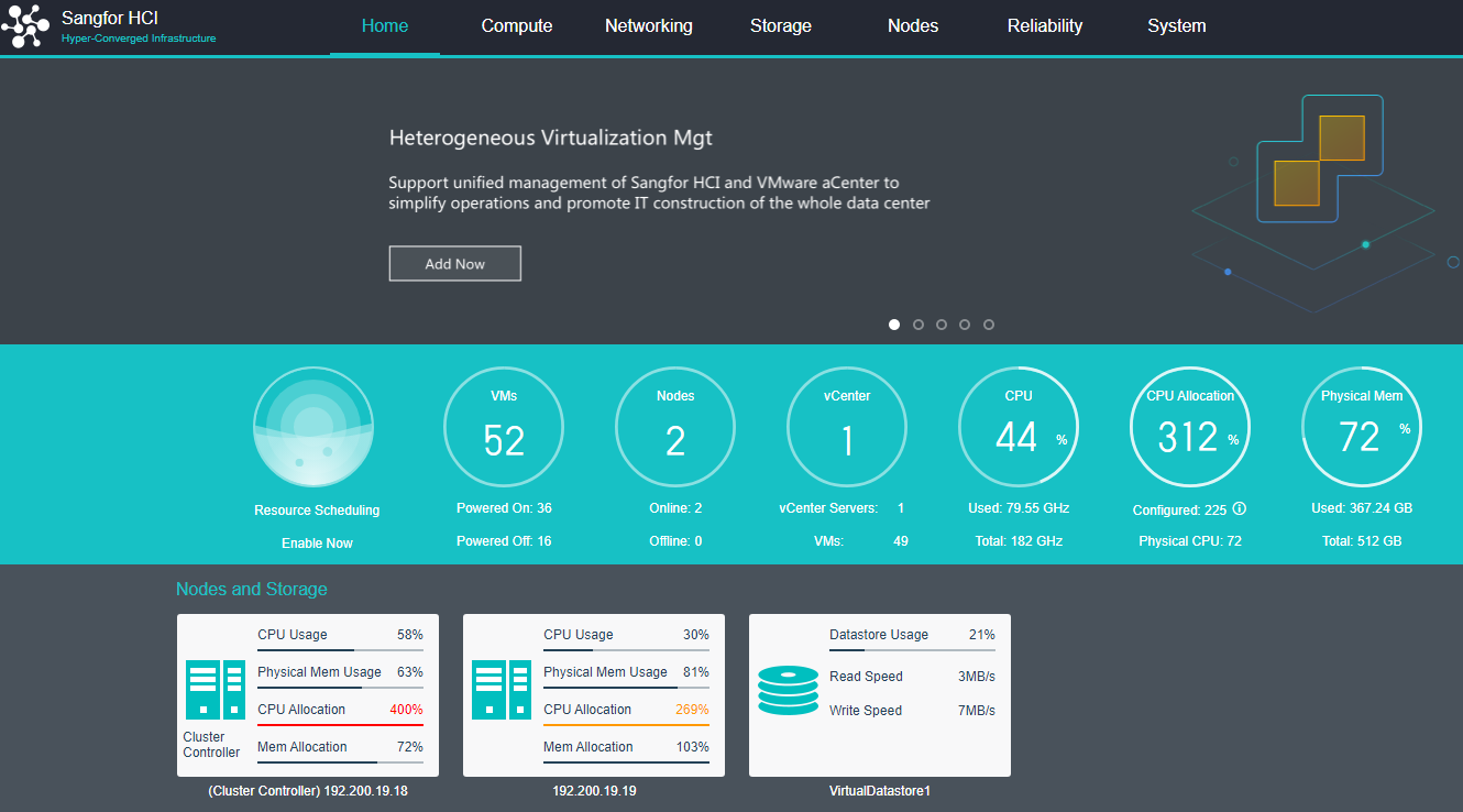
- Under Storage > Virtual Storage > Virtual Datastore, click New to create a new virtual datastore.
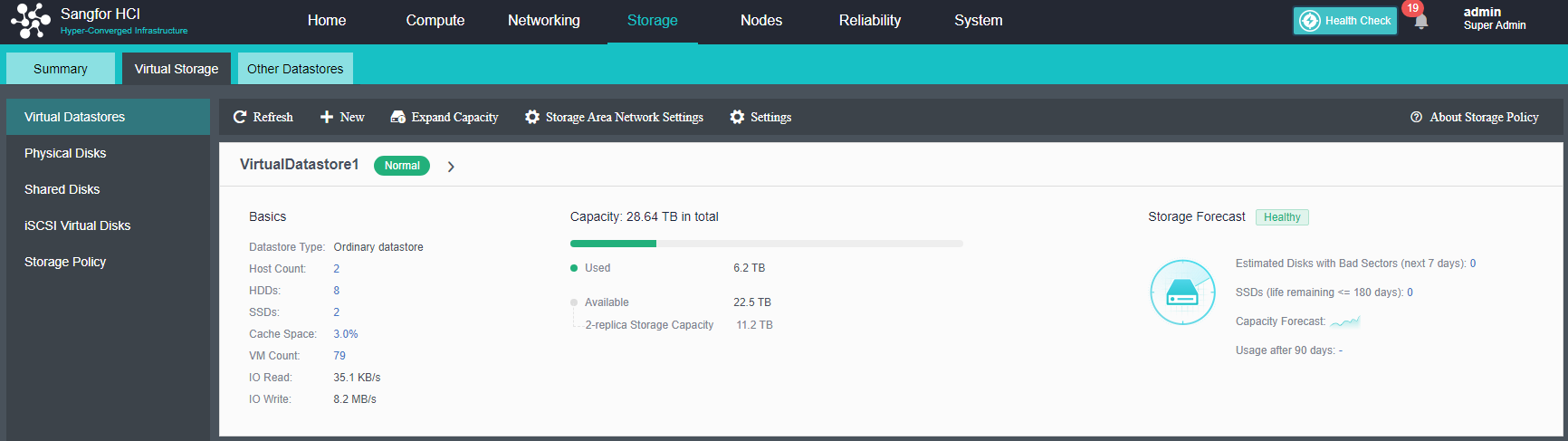
- Click Settings to configure storage interface and IP address.
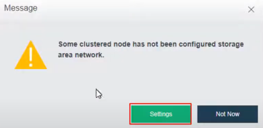
-
Configure the deployment mode according to the Topology as shown below.

-
Select the storage interface and configure IP address.
-
Click New again to create new Virtual Datastore and select Next.
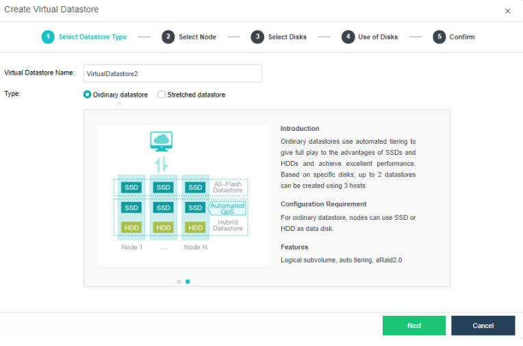
-
For Method, select Use unused disks added to existing datastores.
-
Use disks on new hosts: Select three or more hosts in the cluster to create a new volume.
-
Use unused disks added to existing datastores: Select the unused hard disk in the host contained in the volume and choose to create a new volume.
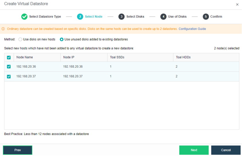
- Select the disks that are required for the capacity expansion.
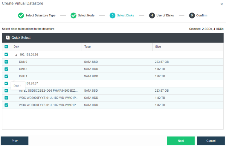
- Configure the disk groups for the new datastore. If it is not a full flash deployment, SSD is required for use as a cache disk.
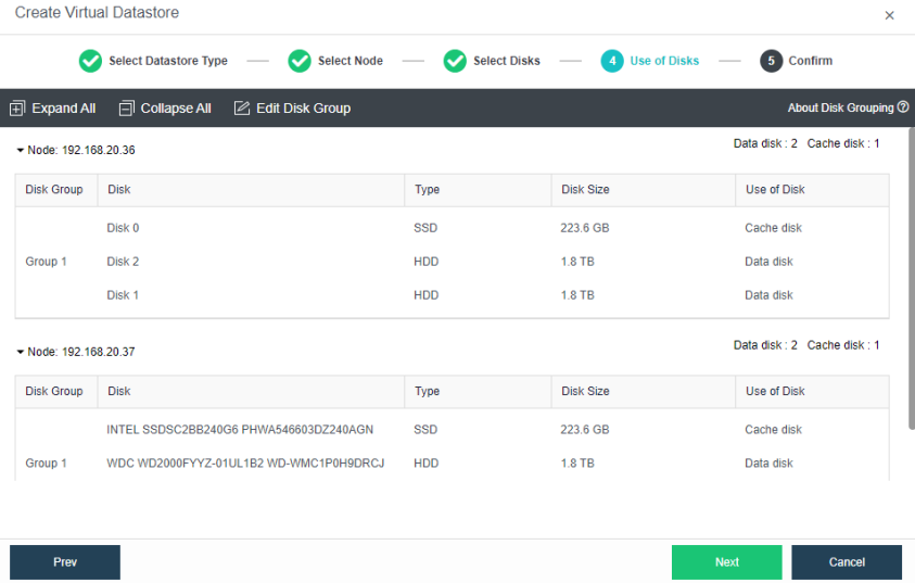
- Verify the configurations and complete the procedure.
Adding hosts
- Click Add New Node in Nodes.
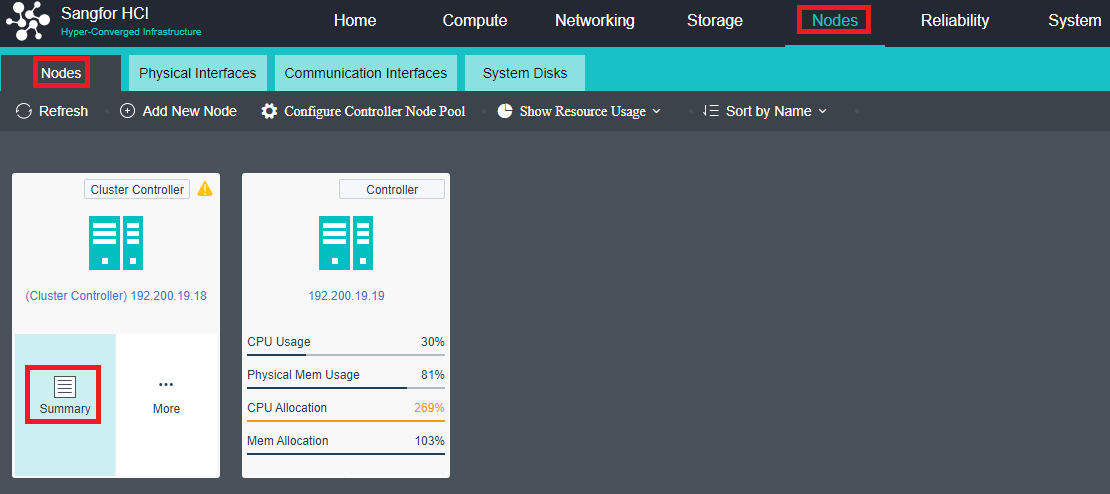
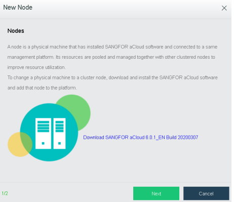
- Select the host that needs to be added. If the host is not shown here, click + icon to add manually.

-
When adding a new host, it will remove the firewall configurations of the host. Click OK to continue.
-
If it is detected that the MTU of the communication interface is inconsistent, reconfigure it and check the Enable high performance mode checkbox.

- After adding a node successfully, configure the communication interface. Then, the new node will be visible under Home.

- Navigate to Storage > Virtual Storage and click New.

- Click Storage Area Network Settings, and it will redirect to Communication Interface > Storage Network Interface. Select Reset Storage Area Network to configure the storage interface and IP address.
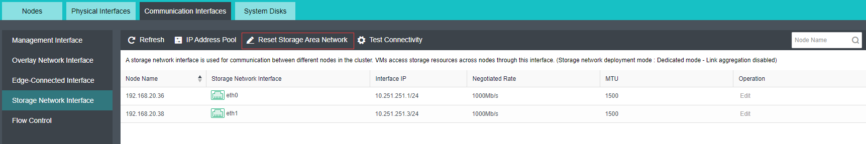
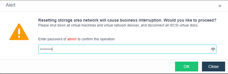
- Configure the deployment mode according to the Topology as shown below.

- Select and configure the storage interface and IP address.
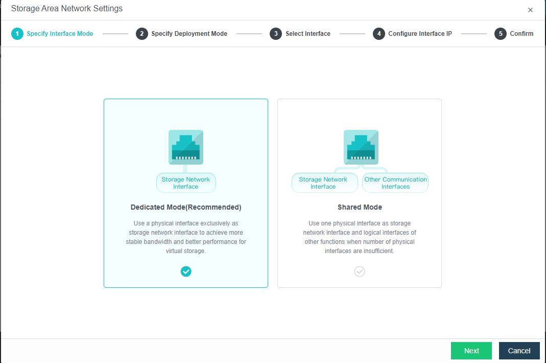
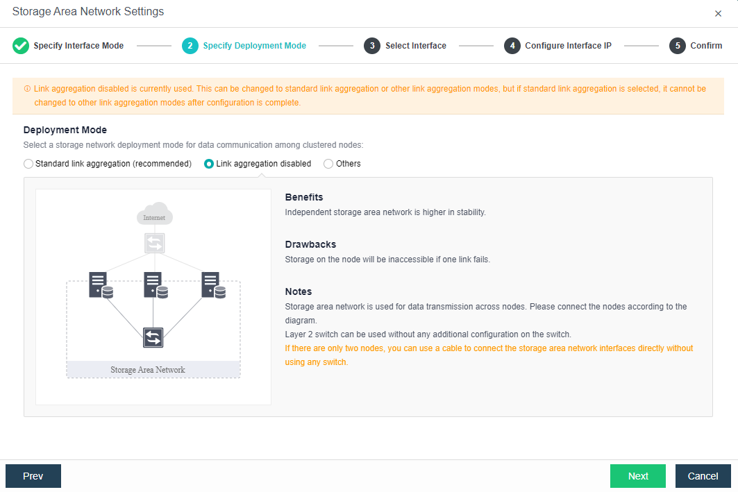

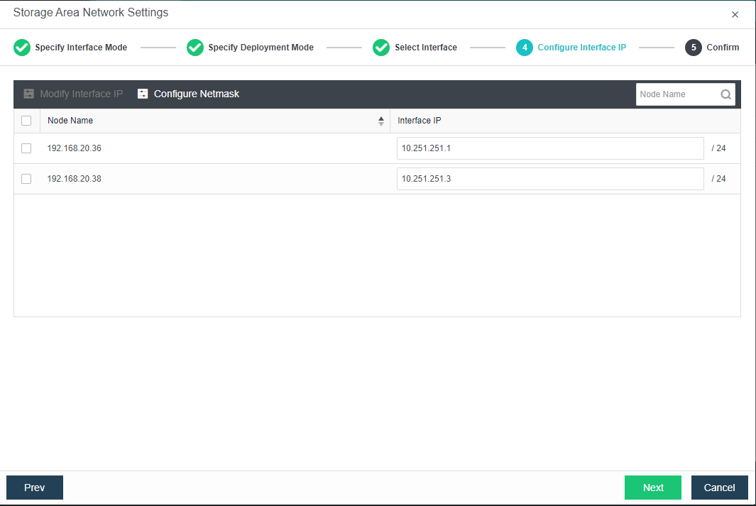
- Click New again to create new virtual datastore and click Next.

-
For the Method, choose Use unused disk added to existing datastores.
-
Use disks on new hosts: Reselect 3 or more hosts in the cluster to create a new volume.
-
Use unused disk added to existing datastore: Select an unused hard disk in the host that the volume contains to choose to create a new volume based on the existing volume.
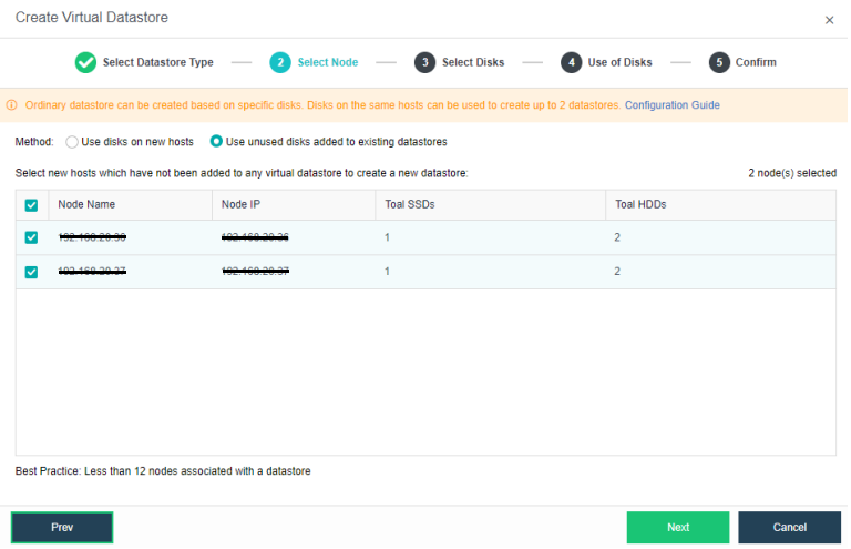
- Select the disks that needs to be included in the disk group.
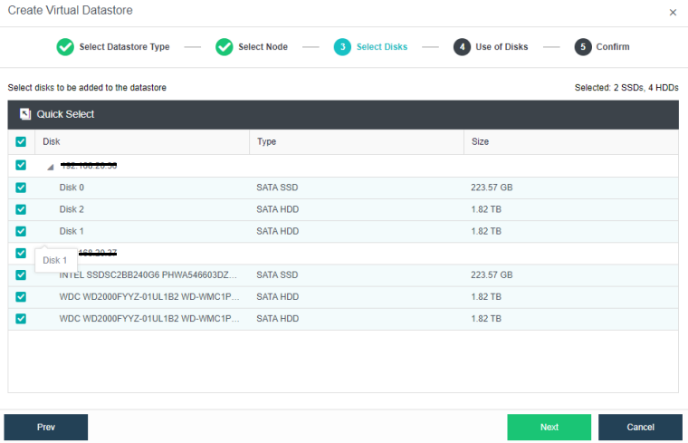
- For the newly created disk groups, an SSD as a cache disk is necessary if it is not a full flash deployment.

-
Verify the configurations, and click OK to complete the operation.
-
Datastore type configuration: Select Storage > Virtual Storage and click New. Select the Type as Ordinary Datastore.
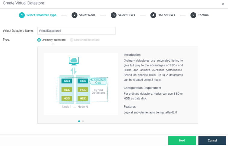
- Select Node: Select the nodes from the cluster, and choose the nodes that need to be included in the virtual datastore volume.
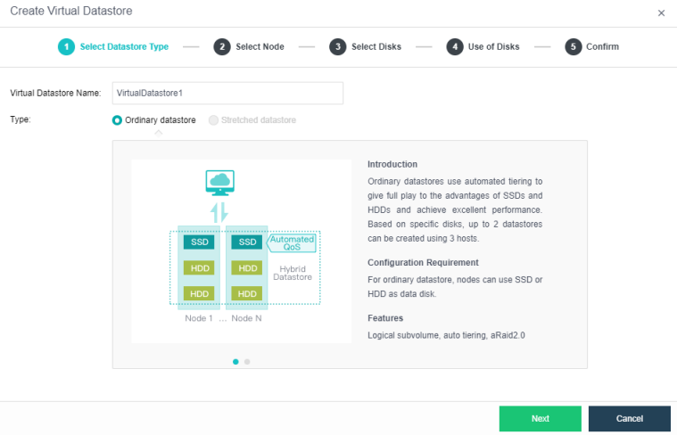
- Select the hard disks that need to be added. Configure the hard disk and disk groups, then set up the use plan for each disk on the hosts. The system will automatically detect the disks of all hosts in the cluster. By default, hard disks are selected as data disks, and solid-state disks are used as cache disks. Using the default configuration is recommended. If you need to deploy multiple disk volumes, you have to plan for backup disks on the second volume group.

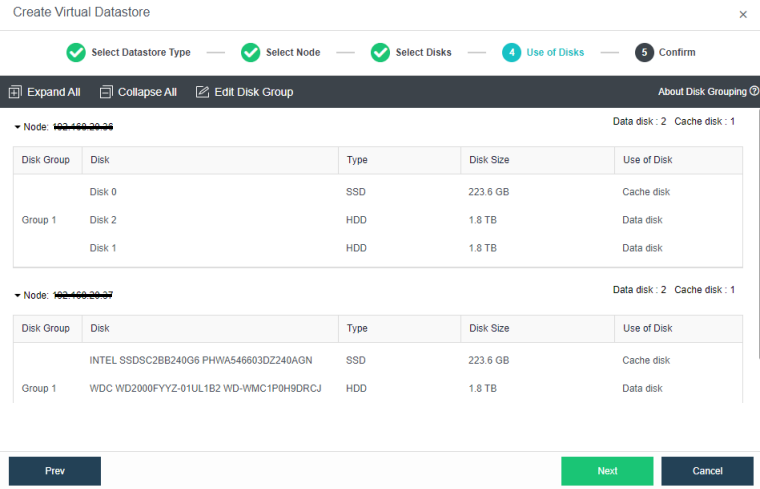
- Verify the configurations, and click OK to complete the process.
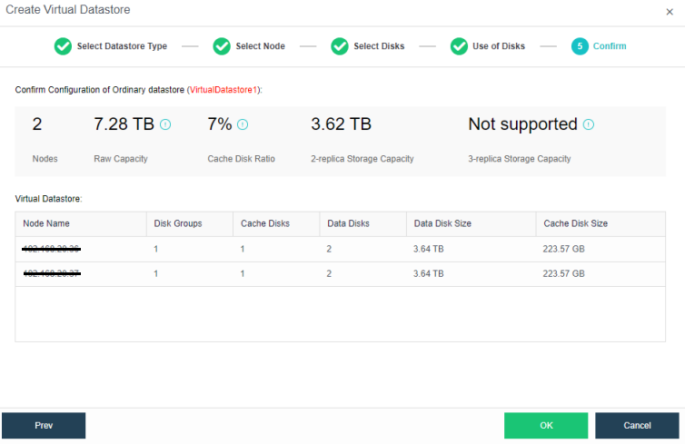
- The following page displays virtual storage configurations, including available disk space, number of data copies, and the total number of disks. After confirming configurations, click OK. Then, input the administrator account password: admin. Then, click Finish to begin initializing virtual storage.
Creating Storage Multi Volume
- Click Add New Node in Nodes.

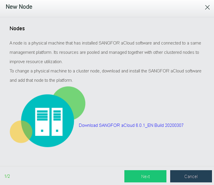
- Select the node to be added. If the node to be added is not in the list, click + to add it.

- Adding a host will delete the firewall configuration of the added host. Click OK.
- If it is detected that the MTU of the overlay network interface is inconsistent, reconfigure it, and check the Enable high-performance mode checkbox.
- After adding a node successfully, configure the communication interface. Then, the new node will be visible under Home.

- Go to Storage > Virtual Storage > Virtual Datastore and click New.

- Click Settings to configure the storage interface and IP address.

- Configure the deployment mode according to the Topology as shown below.

- Select the storage interface and configure IP address.


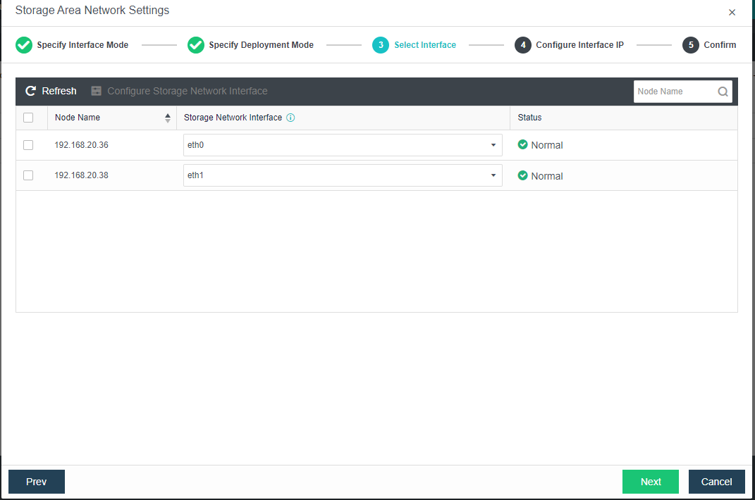

- Click New again to create a new Virtual Datastore and select Next.
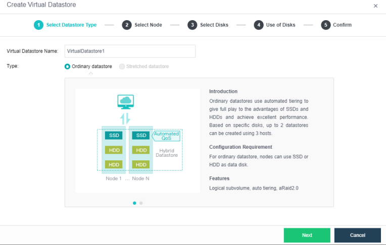
-
For the Method, choose Use unused disk added to existing datastores.
-
Use disks on new hosts: Reselect 3 or more hosts in the cluster to create a new volume.
-
Use unused disk added to existing datastore: Select an unused hard disk in the host that the volume contains to choose to create a new volume based on the existing volume.
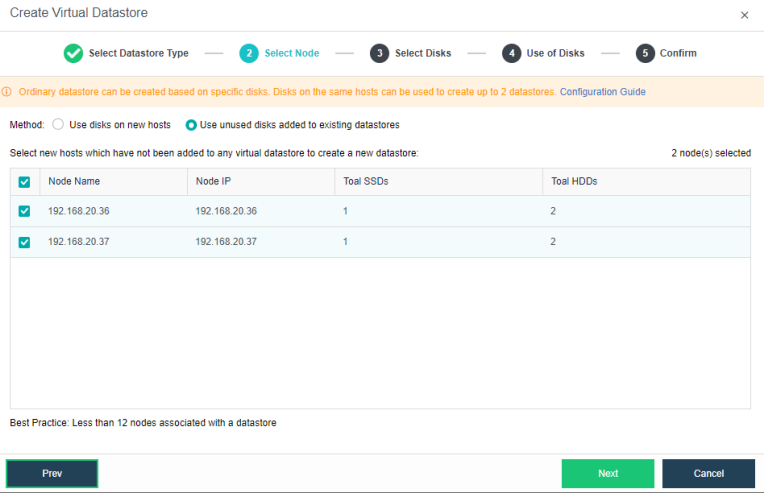
- A list displays node information such as node name, node IP, total SSDs, and HDDs. You should select the node(s) from the list you want to add to the virtual datastore. Note that at least three nodes are required to create a second virtual datastore.

- Specify the use of the disks. Disks added to virtual storage can be used as the data disk, cache disk, or spare disk. If it is not a full SSD, it is necessary to have an SSD as a cache disk.

- Verify the configuration and complete the operation.
- Navigate to Storage > Virtual Datastore, click New, and choose the Type as Ordinary Datastore.
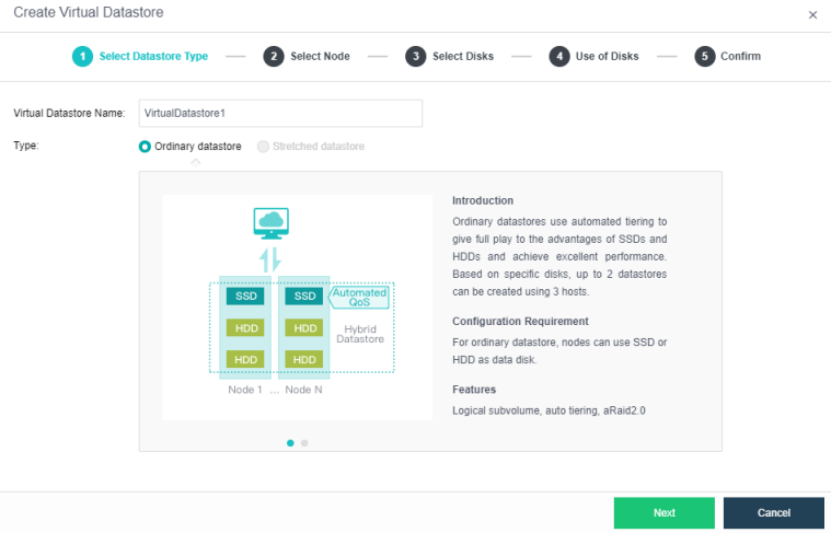
- Select Use unused disks added to existing datastores and select the nodes needed to add to the virtual datastore.
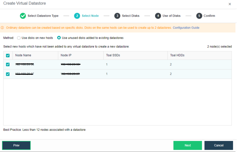
- Select the hard disks that need to be added. Configure the hard disk and disk groups, then set up the use plan for each disk on the hosts. The system will automatically detect the disks of all hosts in the cluster. By default, hard disks are selected as data disks, and solid-state disks are used as cache disks. Using the default configuration is recommended. If you need to deploy multiple disk volumes, you have to plan for backup disks on the second volume group.
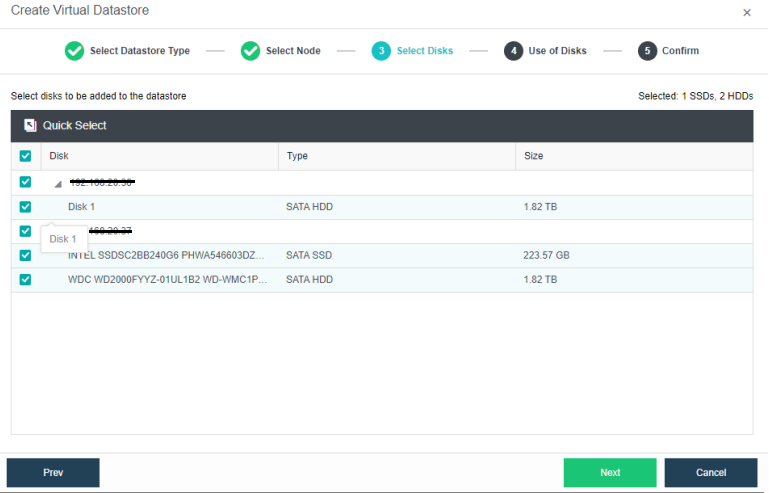
- Specify the use of the disks. Disks added to virtual storage can be used as the data disk, cache disk, or spare disk. If it is not a full SSD, it is necessary to have an SSD as a cache disk.
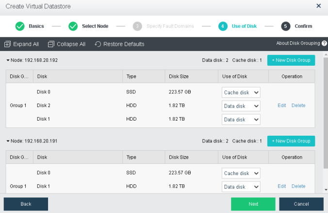
- Verify the configurations.
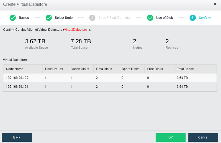
- The following page displays virtual storage configurations, including available disk space, number of data copies, and the total number of disks. After confirming configurations, click OK. Then, input the administrator account password: admin. Then, click Finish to begin initializing virtual storage.
Creating Stretched Datastore
Description
HCI supports multi-volume management. Normal volumes and stretched volumes can exist on a cluster at the same time. Multiple virtual datastore can be created in the HCI cluster, and volumes are physically and logically isolated. But for virtual machines, volumes can be selected and migrated, and they can also meet the heterogeneous hardware requirements of different services in the cluster. The following operations are for adding stretched volumes.
Precautions
- The newly added volume will be formatted when it is created. Before adding, please make sure that there is no data that needs to be preserved on the disk used to add the new volume.
- HCI builds volumes based on the host as the basic unit. Please plan ahead to create a cluster.
- The deployment mode of the witness node supports physical machine deployment and VMware virtualization deployment. Using the management interface to communicate with the data node is recommended.
Prerequisites
- A stretched cluster starts with at least four hosts plus one witness node. In actual deployment, it is necessary to ensure that the node location configured on the page is consistent with the actual physical location. Otherwise, protection at the computer room level cannot be achieved. The two fault domain computer rooms must be connected at Layer 2, and the link of the witness node does not need to be connected at Layer 2, but make sure it is reachable by the network.
Steps
- Configure the volume type and the number of data copies: Navigate to Storage > Virtual Storage > Virtual Datastores, click New, and select the volume Type as Stretched datastore.
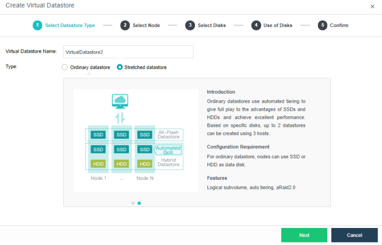
- Select Node: Select the host that needs to be added to the stretched datastore. The stretched datastore requires at least four hosts and set the two hosts in different fault domains.
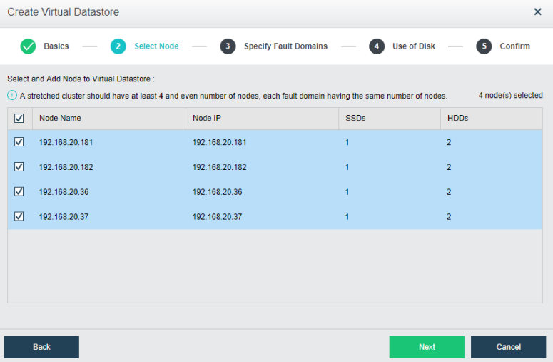
- Specify Fault Domain: Add the required hosts to the corresponding fault domain. In this example, there are four hosts, so two hosts are added to the primary fault domain and two hosts are added to the secondary fault domain.
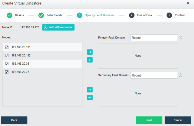
- Add witness node: After configuring the main computer room and the standby computer room, configure the witness node IP according to the pre-installed witness node. Follow the wizard to enter the password to confirm the configuration of the quorum node, and then confirm the configuration.
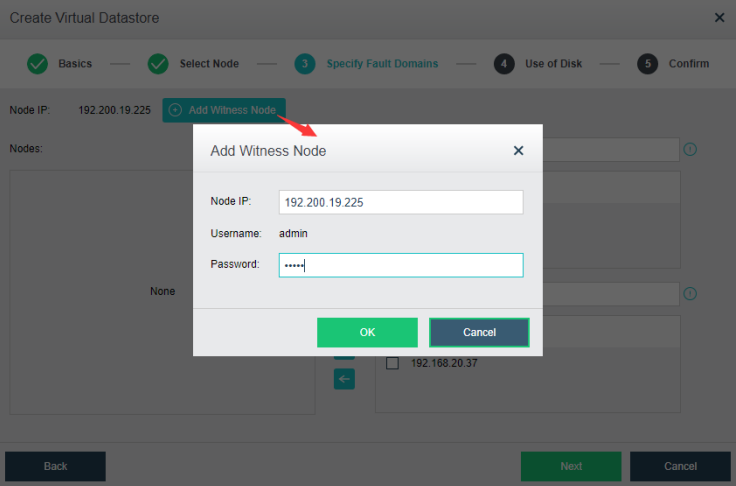
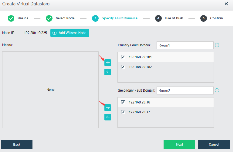
- Verify the configuration: Confirm the configuration of the fault domain. After completion, it is not possible to modify the fault domain.
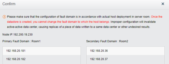
- Configure use of disk: Each node must have a cache disk and data disk.
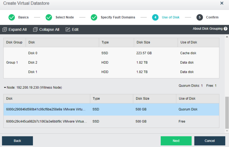
Note:
Stretched virtual datastore has to configure witness node quorum disk. Each quorum disk requires at least 100GB.
- Confirm the configuration: The configuration information of the virtual storage is displayed here, including the final storage capacity, the number of copies, and the number of disks. After confirming that the configuration is correct, you need to enter the administrator password and click Finish to initialize the virtual storage.
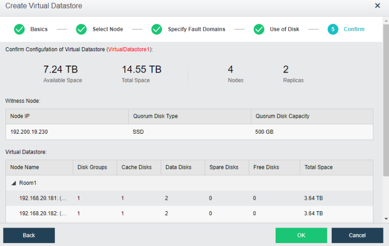
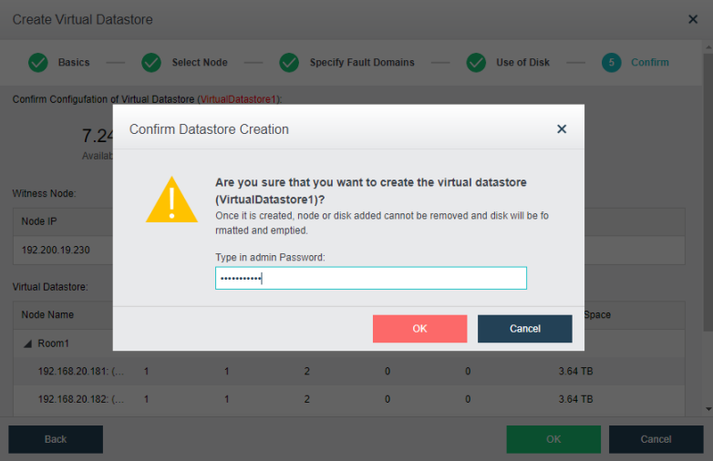
Modify Fault Domain on Stretched Datastore
Description
Due to the active and standby changes, the HCI administrator can switch between active and secondary fault domains by configuring the fault domain.
Precautions
Confirm that the volume that needs to be deleted data is None valid data.
Deleting Volume (High-Risk Operation)
Description
HCI administrators can manage the cluster’s storage by volume, delete a specific volume, remove hosts and expand the cluster.
Precautions
Confirm that the volume that needs to be deleted data is None valid data.
Prerequisites
- Ensure that all the virtual machines running in this virtual datastore are shut down.
- Ensure that the virtual machines running in another virtual datastore but stored in this one are shut down.
- If the iSCSI virtual disks provided by this virtual datastore are not to be used anymore, end all the iSCSI connections.
Steps
-
Go to Storage > Virtual Storage > Virtual Datastore and click on the volume that needs to be removed.
-
On the storage Summary page, click Delete to remove this storage.

- Check the I am sure that all data is safely migrated checkbox and click OK to proceed.
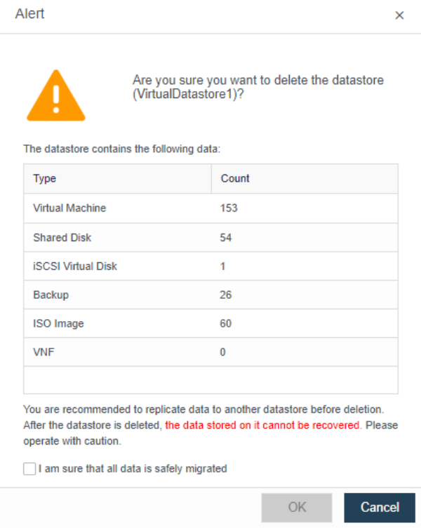
- Enter the HCI administrator password and click OK.
Configuring Data Balancing
Description
You can create data balancing task for different virtual datastores. After the task is created, the available storage space of each node will be restricted to a certain range.
Suppose the remaining storage space is below a certain range. In that case, the data balancing task will be executed automatically to have VM files stored on the node short of resources moved to another node. Data that have been migrated will be evenly written into each disk to keep disk usage balanced.
Precautions
- The schedule set for the data balancing plan is generally recommended to be during idle time of the user’s business so that the I/O generated during data balancing has less impact on the normal I/O of the business. If the balance is not completed within the set time range of the day, the balance task will stop and continue to complete the balance during the next scheduled time.
- Suppose all the disks in the virtual datastore exceed 90%, and the capacity usage of any two disks is less than 2%. In that case, it means that the capacity of the entire virtual datastore is about to be exhausted. The None method has passed the data balancing, so each component is still available. Sufficient space continues to be used for normal data writing, and the virtual datastore space must be expanded at this time.
Prerequisites
- When the user has set a data balancing plan, if the difference between the highest and lowest disk capacity usage in the volume is found to exceed 30%, the balance is triggered until the usage of any two hard disks in the volume does not exceed 20%.
- Suppose the user does not set a data balancing plan when the space usage of a certain disk in the virtual datastore exceeds 90%. In that case, automatic balancing is triggered until the highest and lowest disk capacity usage in the volume is less than 3%.
Steps
- Go to Storage > Virtual Storage and click Settings.

- Select Data Balancing, and configure the schedule for the data balancing task. It is recommended to schedule during the non-production hour.
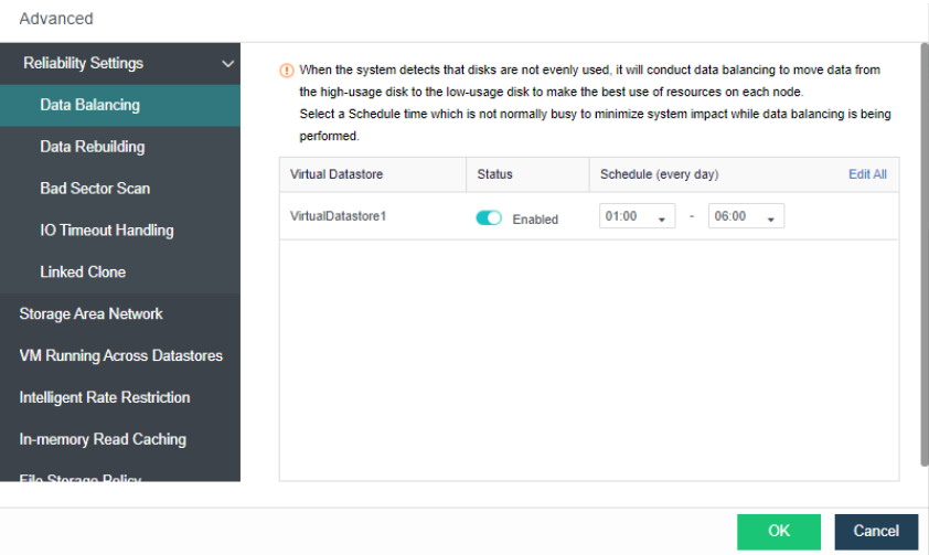
Configure Bad Sector Scanning
Description
Hard disk will be periodically scanned for bad sectors. If any bad sector is detected, disk repairing will be conducted. To ensure scanning speed, it is better to perform scans during off-peak hours.
Precautions
- Bad sector scanning is for hard disks, and a full-flash environment does not support bad sector scanning and repair.
- The bad sector scan will be performed within the configured period. If the current round of scans is not completed on time, it will start from the end of the current scan during the next scan.
- The speed of bad sector scanning will be dynamically adjusted according to the load of the disk, and the impact on storage performance is <5%.
- Bad sector scanning and repairing are only performed on the occupied area in the disk and not on the blank area of the disk.
- Stretched clusters only support bad sector scanning, not bad sector recovery.
- When a bad sector repair task is initiated, there will also be a data synchronization task on the interface.
Prerequisites
None.
Steps
- Go to Storage > Virtual Storage and click Settings.
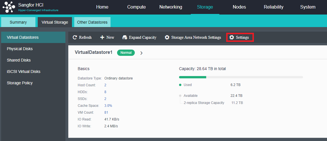
- Configure schedule for Bad Sector Scan.
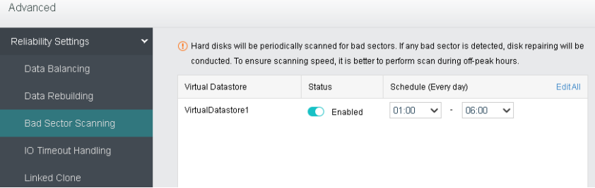
- After enabling, there will be a bad sector scanning task on the HCI task list.
Configuring Data Rebuilding
Description
Take the data with a two-copy policy as an example: When components (disk or node) in a virtual datastore suffer a physical fault, another copy of the data is stored on other components to ensure normal reading and writing of the virtual machine. As a result, the redundancy of the virtual datastore is reduced, leading to data loss if the component storing the other copy breaks down. With data rebuilding, when a component breaks down, the other copy of the data on the faulted component will be used as the recovery source to rebuild a new copy on the target component in fragments to recover the completeness of the copy and realize system self-recovery.
Precautions
- To use the automatic rebuilding feature, the number of HCI clustered nodes must be four or more.
- When the two nodes have No spare disks when a disk failure occurs, automatic rebuilding is not supported.
Prerequisites
- Node mutual exclusion between replicas of shards must be satisfied.
- If condition 1 is satisfied, there are disks in the cluster where disk capacity does not exceed 85%.
Steps
- Go to Storage > Virtual Storage and click Settings.

- Select Data Rebuilding, and configure the wait time for host rebuild and disk rebuild.
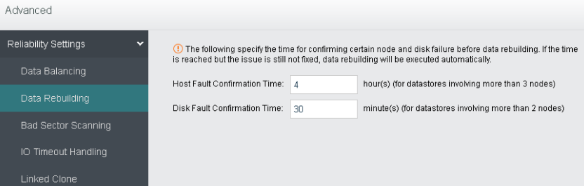
Configuring Snapshot Restriction
Description
The snapshot restriction adjusts the tiered elimination and write-back thresholds to prevent the cluster business services from being affected by too many scheduled snapshots.
Precautions
This feature is not enabled by default. After it is enabled, the thresholds for hierarchical write-back and elimination may be adjusted, which may affect the performance of some business services. It is recommended to enable it only in scenarios where scheduled snapshots are used for security protection.
Prerequisites
N/A
Steps
- Navigate to Storage > select Virtual Storage > click Advanced.
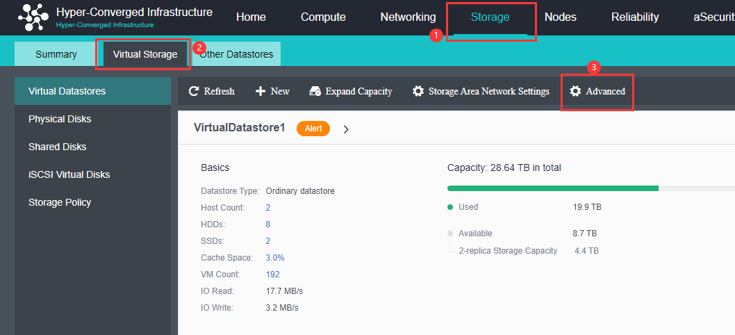
- Select Intelligent Rate Restriction, and set Snapshot Restriction to Enabled.
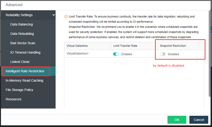
Modify Storage Network Interface (High-Risk Operation)
Description
The private storage network is to build a communication network for virtual storage alone, which can improve the efficiency of data transmission and ensure the consistency of data synchronization.
Usually, virtual storage contains very important user data. To avoid the risk of data synchronization caused by network problems, a storage private network can be built to protect it. However, the storage private network requires the physical node to provide a separate interface for storage communication.
Precautions
-
Check that the storage private interface adopts the link aggregation mode or 10 Gigabit interface.
-
It is forbidden to adjust the network wiring during the operation of the HCI platform because plugging and unplugging the network cable will cause the alternate network disconnection, resulting in data split-brain and data loss.
-
Do not remove the cache disk during HCI operation. Replace disks through Disk Management if necessary, or stop processing.
-
When the storage is changed from None link aggregation to another mode, it is necessary to ensure that the node has at least one free network interface. Otherwise, the network deployment mode will remain the same.
Prerequisites
All running virtual machines and virtual network devices need to be shut down.
Steps
- Go to Nodes > Communication Interface and select Storage Network Interface.
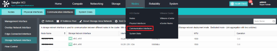
-
On the Storage Network Interface select Reset Storage Area Network.
-
Based on the diagram, select the Dedicated Mode.
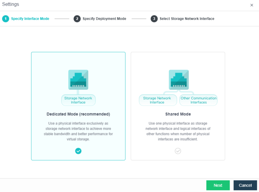
- Specify the deployment mode of the storage network interface. In this case, select Link aggregation disabled.

- Configure the storage network interfaces.
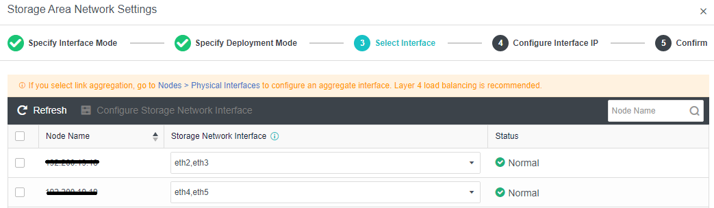
- Configure the private network IP address for the storage network. It is compulsory that the private network IP address of the storage must be in the same IP segment.
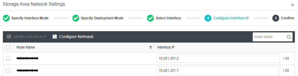
- Verify the storage network interface configurations.
Modify the Test Connectivity IP Address
Description
Test Connectivity is a network connectivity tester that performs ping to test the network communication and judges whether the network is disconnected.
Precautions
- Only two node environment requires the Test Connectivity feature. Three nodes environment is not required.
- Test connectivity IP address must be on the same segment as HCI management IP and pingable.
Prerequisites
None.
Steps
- Go to Nodes > Communication Interface and select Storage Network Interface.

- Click Test Connectivity.
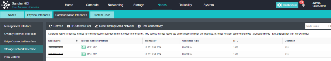
- Fill in the IP address that used for check connectivity. It is suggested to use the gateway address of the management IP.
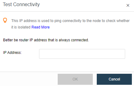
Configure IP Address Pool
Description
Configuring a virtual IP pool allows virtual machines to run across a virtual datastore.
Precautions
If there is only one volume, there is no need to configure a virtual IP pool. Make sure there is no other cluster or node that uses the IP of this subnet.
Prerequisites
Configure 2 or more storage volumes in the cluster.
Steps
- Go to Storage > Virtual Storage > Virtual Datastores and select Advanced.
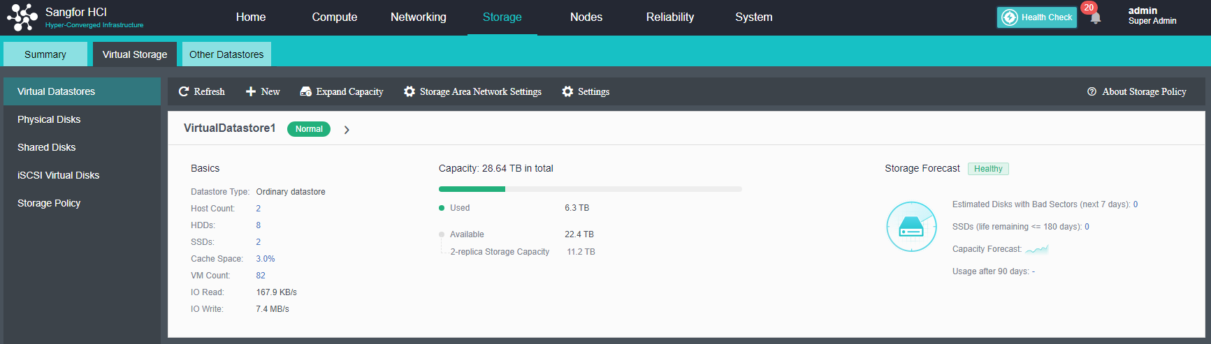
- Select VM Running Across Datastores and fill in the IP Address Pool.
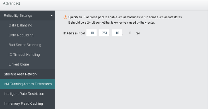
In-Memory Reach Caching
Description
In-memory read caching accounts for 1/16 of node memory, which the virtual machine cannot use. You may disable it and change to cache size.
Precautions
None.
Prerequisites
None.
Steps
- Go to Storage > Virtual Storage > Virtual Datastores and select Advanced.

- Go to In-Memory Read Caching and click Settings. And can choose whether this function takes effect for all IO block sizes or specific block sizes only.
- In high-performance database scenarios, it is recommended to configure higher memory at a ratio of 1/4 of the node.
- For common scenarios, the memory is allocated in a ratio of 1/16 or 1/8.
- In scenarios where performance requirements are not high but multiple virtual machines are required to run, it is recommended to turn off memory performance optimization.
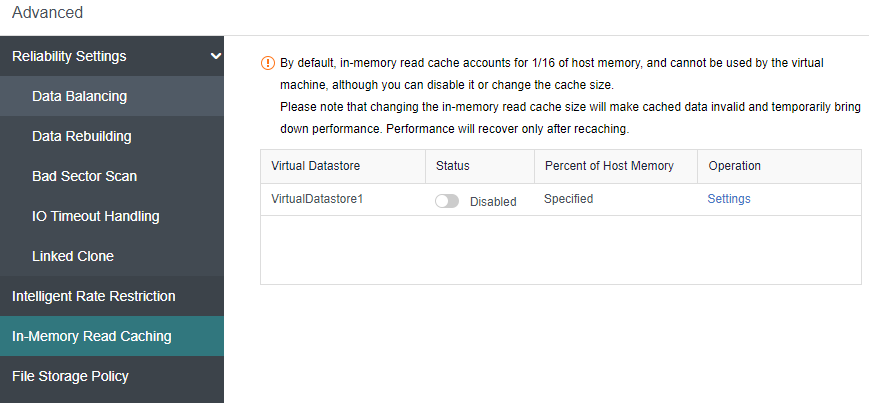
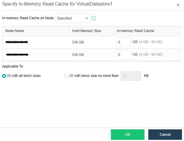
Creating a new Shared Disk
Description
The shared disk is mainly configured to use with Oracle RAC. Deployment using shared disks greatly simplifies the complexity and cost of Oracle RAC’s traditional deployment mode and supports uninterrupted business switching of 100 shared disks.
Precautions
To configure Shared Disks on the HCI cluster, it is necessary to have at least three nodes or above.
Prerequisites
None.
Steps
- Configure IP Address Pool: Go to Nodes > Communication Interface > IP Address Pool and click IP Address Pool to configure the address pool accordingly.
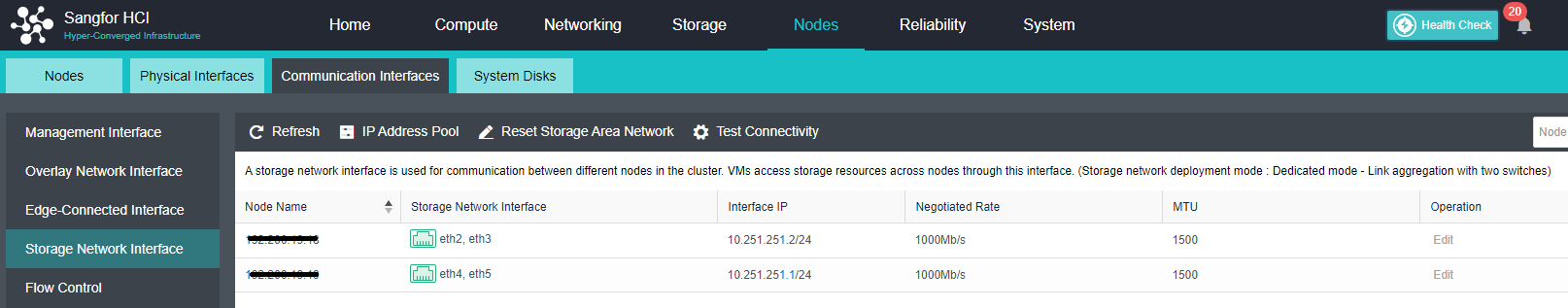
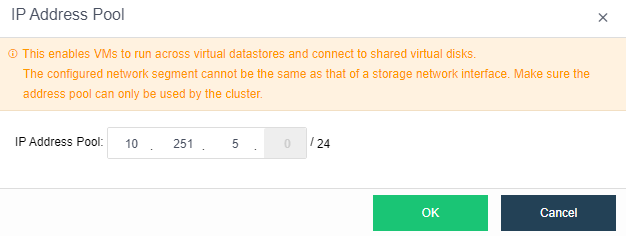
- Create new Shared Disks: Go to Storage > Virtual Storage > Shared Disks, click New to create a new Shared Disk.
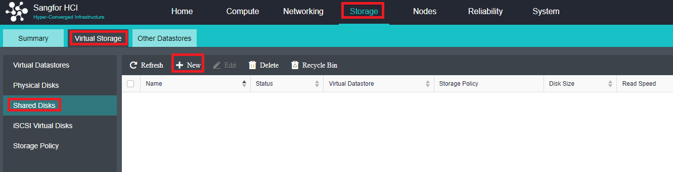
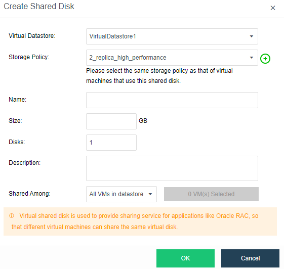
- Configure shared disk: Select the shared disk that needs to be modified, and press OK.
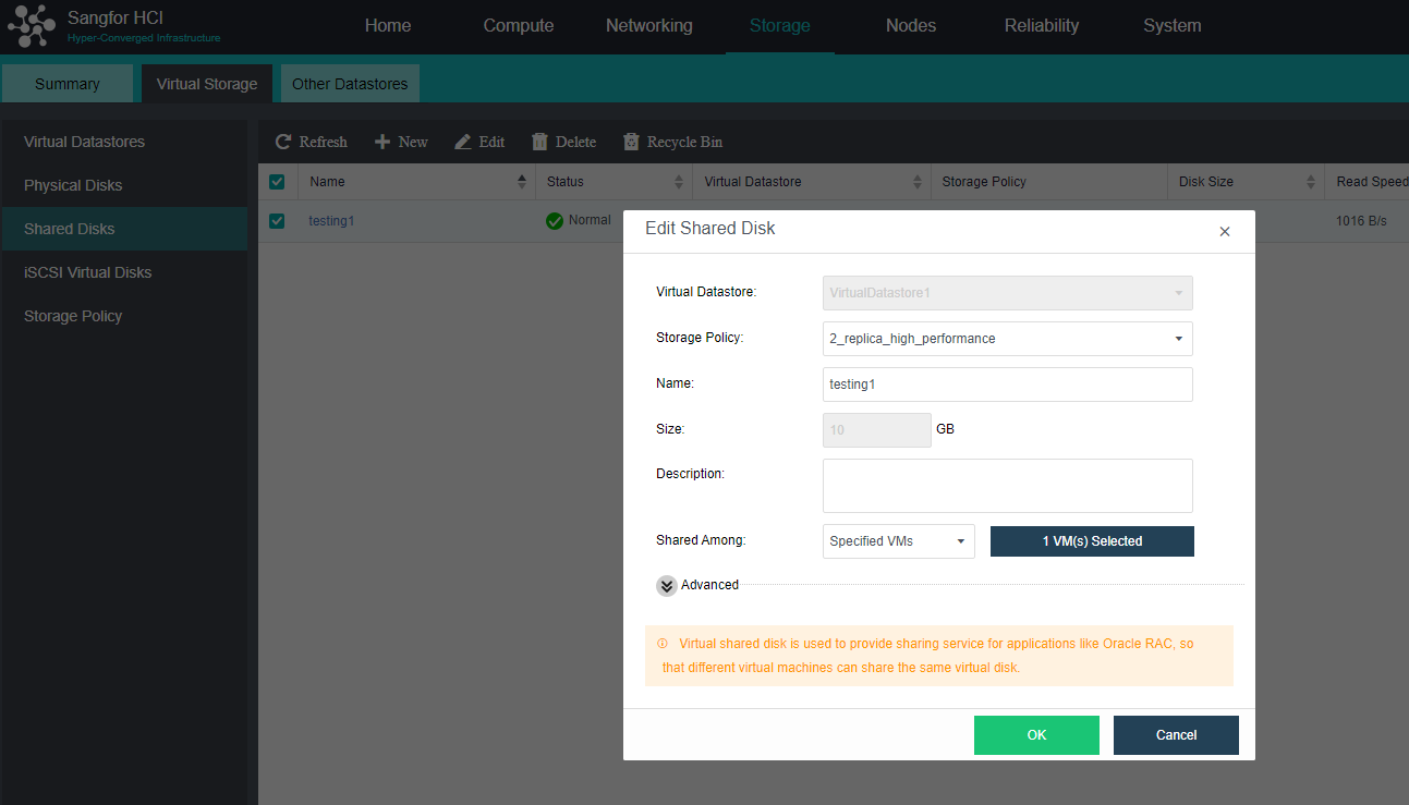
Delete Virtual Shared Disks
Description
Delete the shared disk that is not in use.
Precautions
None.
Prerequisites
Shared Disk nodes connection must be 0.
Steps
- Select the Shared Disk that needs to be deleted, click on Delete.
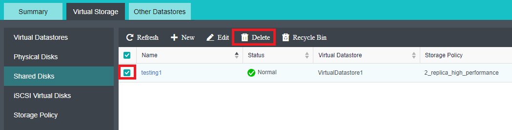
- Click Confirm to proceed with the deletion of shared disk.
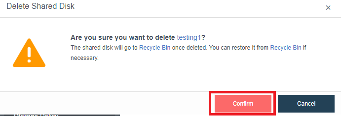
Storage Policy
Description
Different storage policies can be selected according to different business types. After a virtual storage volume is created, the virtual storage will automatically generate built-in storage policies based on commonly used storage configurations. If the built-in policy does not meet the requirements, you can add a new storage policy to customize storage-related configurations such as replicas, automated QoS, and stripe width.
Precautions
None.
Prerequisites
None.
Steps
-
Go to Storage > Virtual Storage and select Storage Policy to view the storage policies.
-
The most common scenarios and default policies are as shown below:
- Ordinary VM: 2 replicas default policy.
- Deploys Oracle, SQL Server: 3 replicas high-performance policy.
- Configures Shared Disks: 3 replicas high-performance policy.
- Configure iSCSI Virtual Disks: 2 replicas default policy.
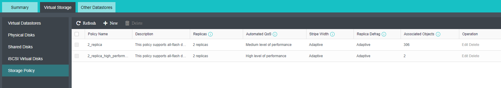
- Click New to create a new storage policy. Fill in the policy name and description and select the replicas, stripe width, and automated QoS.
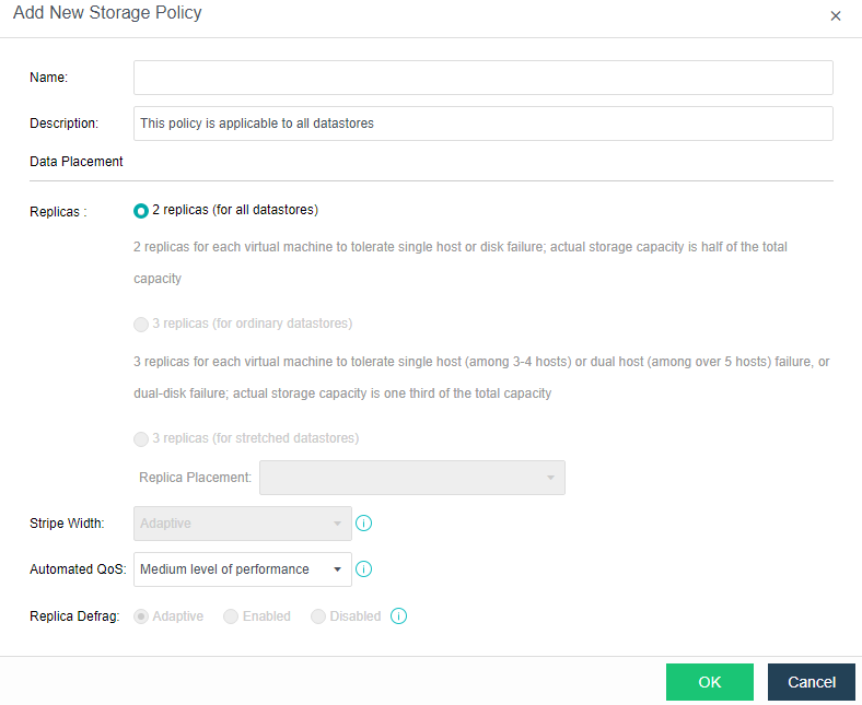
Configure Virtual iSCSI Disks
Description
iSCSI virtual disks are used by users who have iSCSI storage requirements. Part of the virtual storage can be divided to provide services in iSCSI storage.
Precautions
The configured virtual iSCSI disk size can be pre-allocated or not. If it is pre-allocated, a 100G disk will occupy 100G of space on HCI. Storage space is allocated on demand if Pre-allocate is not selected.
HCI platforms must have virtual storage before configuring virtual iSCSI disks because iSCSI Virtual Disks are based on virtual storage.
Prerequisites
None.
Steps
- Go to Storage > Virtual Storage and select iSCSI Virtual Disks.
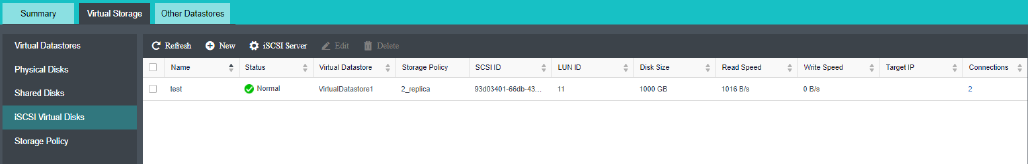
- Select the virtual datastore that will provide service to iSCSI and click Settings.
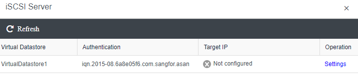
- Configure the iSCSI authentication username and password.
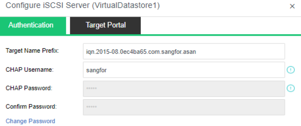
- Configure the Target Portal.
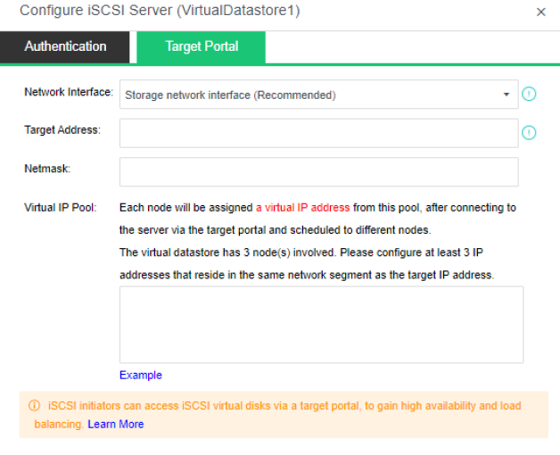
- On the iSCSI Virtual Disks tab click New to create new iSCSI Virtual Disk.
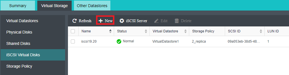
- Select the storage volume, configure the name, disk size, and accessible clients. Enabling Pre-allocation will give priority to occupying the SSD cache disk space. At the same time, you can limit the connected clients and whether to allow multiple clients to access them at the same time.
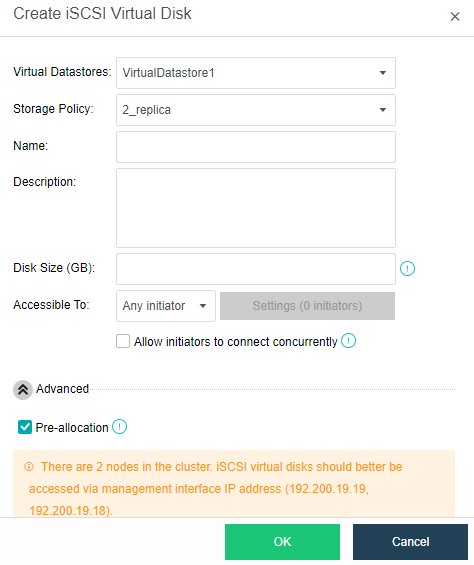
Disk Maintenance Mode (HDD isolation)
Description
When the lifetime of the hard disk has reached the end, the number of bad sectors is too high, and the hard disk is in a bad health state, it is necessary to replace the hard disk. If a data synchronization task needs to read data from the hard disk to be replaced, unplugging the hard disk at this time may cause a double-point failure and affect production. This is where disk maintenance mode comes in handy. Before isolating the hard disk, a comprehensive inspection of the data will be performed to ensure that the production will not be affected when the hard disk is isolated.
Precautions
- Support the maintenance mode of the data disk and cache disk.
- There are two ways to enter maintenance mode.
Data migration:
-
The popup box prompts the need to relocate ** GB of data(depending on the actual environment) to enter the maintenance mode. Check the box before proceeding to the next step. (If it is a cache disk, migrate all data in the disk group where the cache disk is located).
-
It will prompt that you need to wait for the data to be migrated completely successfully before entering the maintenance mode.
-
Prompted to migrate the affected virtual machine on the data disk.

Does not migrate data:
- Only ensure that the data involved in the disk can still be accessed after the disk is offline.
Prerequisites
The hard disk is in a bad health condition.
Steps
Hard Disk Isolation
- Navigate to Storage > Virtual Storage > Physical Disks, and click the affected hard disk.
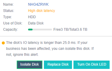
-
Click Isolate Disk, and you will be prompted to choose how to process the data.
-
When performing hard disk isolation, you can select Quick Isolate. If you choose this method, the replacement time will be shorter, and at the same time, there will be a single copy time window. If you select Prioritize data integrity, the system will first migrate the data on the hard disk to other disk groups to ensure that there are always two healthy copies of data in the environment.
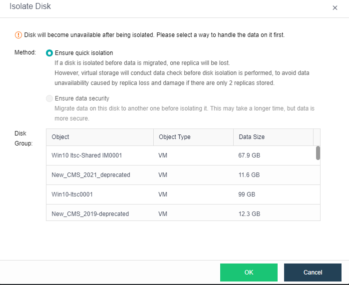
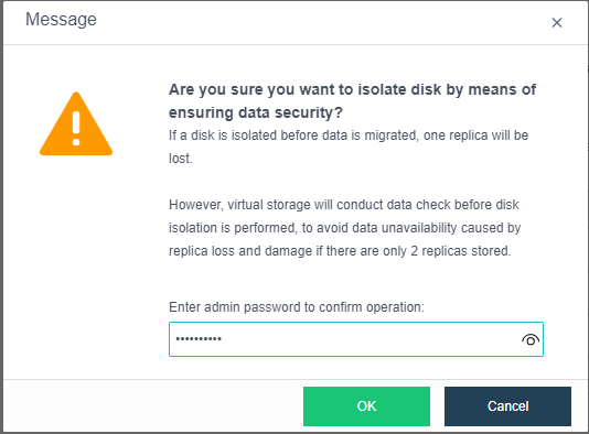
Replace Hard Disk
-
Enter the Storage > Virtual Storage > Physical Disk and click the affected hard disk.
-
Click Isolate Disk, and you will be prompted to choose how to process the data.

-
When performing hard disk isolation, you can select Quick Isolate. If you choose this method, the replacement time will be shorter, and at the same time, there will be a single copy time window. If you select Prioritize data integrity, the system will first migrate the data on the hard disk to other disk groups to ensure that there are always two healthy copies of data in the environment.
-
After the disk isolation is completed, enter the Storage > Virtual Storage > Physical Disk interface, click the affected hard disk and click Replace Disk.
-
On the node, first, unplug the failed disk, then insert the new disk, check I’m ready, and click Next.
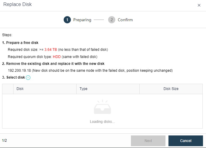
-
Select the new disk and click Next.
-
Confirm the information about the new disk and the faulty disk, check the I’m sure I want to replace the disk checkbox, and click Finish, and then the platform starts to replace the disk.
Healthcheck and Bad Sector Prediction
Description
Collecting hardware information predicts the bad sectors of the hard disk within seven days. In addition, it cooperates with bad sector scanning to detect and repair bad sectors in time to ensure higher data reliability.
Precautions
-
Bad sector prediction only supports SATA HDDs of Seagate and Western Digital brands.
-
Disks under non-virtual datastore do not support bad sector prediction.
-
The bad sector prediction only predicts if the hard disk will have bad sectors in the next seven days.
-
After upgrading to a lower version or creating a new virtual storage environment, the bad sector prediction result will not be generated until the environment continues to run for seven days.
Prerequisites
None.
Steps
- Navigate to Storage > Summary, and click Storage Forecast to view the disk’s bad sectors.
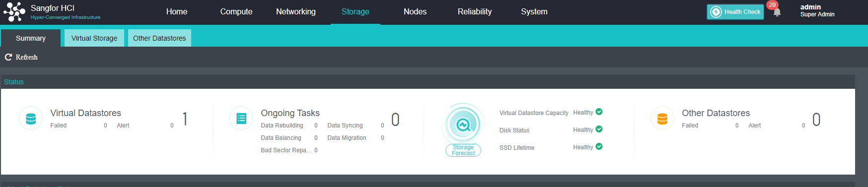
- Click Bad Sectors to open the Bad Sector Details tab, where you can view the progress and status of the specific scan.
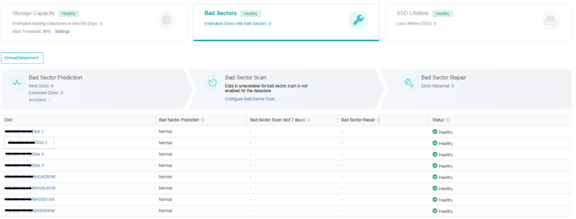
Storage Forecast
aSAN analyzes a large number of actual business scenario data. The underlying algorithm library integrates various machine learning and deep learning algorithms and independently develops a storage forecast module, including bad sector prediction, capacity prediction, and SSD lifetime prediction.
Bad Sector Prediction
Description
Sangfor independently developed a high-accuracy bad-sector prediction function by collecting and analyzing the SMART data, performance parameters, and hard-disk log information of bad-sector hard drives in many customer real usage scenarios, combined with advanced algorithm training models. The accuracy of aSAN bad sector prediction is over 95%.
aSAN can dynamically sense which hard disks in the cluster are most likely to have bad sectors according to the upper-layer production load and the usage of cluster hard disks and perform bad sector scanning on them first. This can reduce the actual window of hard disk bad sectors found from the original one week or even one month. It can be shortened to one day. Combined with aSAN bad sector scanning and repair, closed-loop processing of hard disk bad sectors is formed, which significantly shortens the risk period of data being in a single copy due to hard disk bad sectors.
In the bad sector prediction interface, users can see the bad sector prediction results, actual scan results, and bad sector repair status of the hard disk. At the same time, the risk assessment of the hard disk will be performed according to the number of bad sectors in the hard disk. An alert is generated to prompt the user to replace the hard disk as soon as possible to prevent data loss due to hard disk damage caused by too many bad sectors.
Precautions
None.
Prerequisites
None.
Steps
-
Go to the Storage > Summary page, and you can view the health status of the hard disk in the Storage Forecast module.
-
Click Bad Sectors to view the hard disk’s bad sector prediction result and repair status.
-
Hard drives with cumulative physical bad sectors greater than or equal to 40 are rated as risk.
-
Hard drives with cumulative physical bad sectors of 100 or more are rated as high-risk hard drives.
-
Perform risk assessment on hard disks based on the total number of physical bad sectors accumulated in history. Please replace hard disks rated as risk or high-risk in time.
Capacity Forecast
Description
aSAN can dynamically predict the capacity growth trend in the next 90 days according to the capacity usage of customer clusters. In the capacity prediction interface, the user can switch and view the raw capacity, actual used capacity, and dynamic prediction curve of different virtual datastore. It will prompt the user that the used capacity will reach the capacity alert threshold (90%) in XX days.
Precautions
Predicted results are available after 180 days of use for newly deployed clusters.
Prerequisites
None.
Steps
-
Navigate to Storage > Summary, where you can view the health status of virtual storage capacity in the Storage Forecast module.
-
Click Storage Forecast to view the prediction result of virtual storage capacity.
-
Risk: The usage rate will be predicted to exceed the alert threshold after xx days.
-
High risk: The usage rate will be predicted to exceed the alert threshold after xx days.
-
When the virtual storage capacity usage is predicted to be high risk or risky, start the virtual storage capacity expansion process as soon as possible.
SSD Lifetime Prediction
Description
aSAN collects and analyzes the IO data of SSD hard disks in the cluster, calculates the remaining lifetime of SSD hard disks, and displays the expected remaining available time of SSD in combination with the upper business pressure. According to the prediction results, it is divided into three-lifetime levels: Healthy, Medium Risk, and High Risk. Notify users to replace the SSD hard disks in the cluster in time.
Precautions
None.
Prerequisites
None.
Steps
-
Go to the Storage > Summary page, and you can view the health status of SSD lifetime in the Storage Forecast module.
-
Click SSD Lifetime to view the prediction results and alerts of the SSD lifespan.
- Assess the risk of SSD drives based on the remaining lifetime and estimated remaining usable time. It is recommended to replace risky and high-risk SSDs as soon as possible.
- High risk: Remaining life <=10%.
- Medium risk: Remaining life <=15%.
- Health: Remaining life>15%.
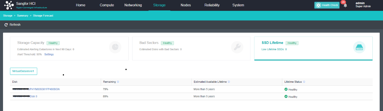
Handling Slow Disk
Description
When there is a problem with a hard drive, the IO activity on that hard drive may freeze or slow down. After the Sangfor HCI platform identifies the slow disk, the virtual storage will automatically isolate the slow disk to avoid continuous impact on the customer’s business.
Slow Disk:
- A slight slow disk alert will be generated if the 60-second IO latency exceeds 25 milliseconds within 5 minutes.
- If the 60-second IO latency is greater than 125 milliseconds within 5 minutes, the hard disk will be isolated, and a serious slow disk alert will be generated.
Frozen Disk:
- When IO does not respond for more than 3 seconds, it is considered that IO has been stuck. If the IO does not respond for 10 seconds in 13 seconds, the disk is considered a freeze. The software will isolate and switch the read/write source to a normal disk.
HDD Slow Disk Handling
Description
This chapter guides the administrator in handling the slow HDD.
Precautions
- It only supports virtual storage scenarios. This function does not apply to non-virtual storage scenarios.
- Two node scenarios do not support automatic isolation of hard disks and require manual isolation. Data Disk rebuilding is not supported after isolation. The hard disk must be replaced as soon as possible to ensure data integrity.
- The spare disk will not automatically replace the isolated disks.
- The slow disk will not automatically be isolated when the node and hard disk are in maintenance mode.
- Before automatically isolating the hard disk, the virtual storage will check the integrity of the replica. If it detects that other nodes have copies in an abnormal state, isolating the current hard disk may cause the virtual machine on the hard disk to run in the None method. Manual isolation can be done according to the current situation, but this situation may cause business interruption.
- The slow disk that appears during the upgrade process will not be automatically isolated.
- If there is a restart node operation, the slow disk processing service will take effect after half an hour.
Prerequisites
None.
Steps
Log in to the HCI platform and view the hard disk status on the Storage > Virtual Storage > Physical Disks interface. The interface will generate an alert prompt when a slow disk failure occurs.
- When a slight slow disk alert occurred and the service is affected, you can click Isolate Disk to manually isolate the hard disk;

- When a critical slow disk alert appears, the software will automatically isolate the hard disk, and it is recommended to replace the disk as soon as possible.
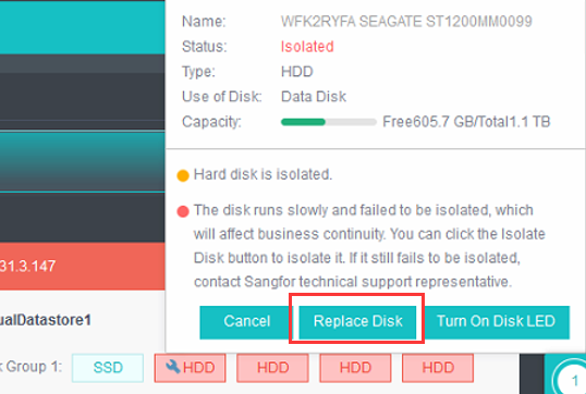
SSD Disk Latency Handling
Description
This chapter guides the administrator in handling SSD disk latency.
Precautions
- The following situations do not support the automatic isolation of slow SSD:
- The system disk will not be automatically isolated when it is in high disk latency. Please contact Sangfor technical support for handling.
- Two nodes scenario does not support the automatic isolation of disks, so manual isolation is required, and disk data rebuilding is not supported after isolation. The hard disk must be replaced as soon as possible to ensure data integrity.
- The slow disk will not automatically be isolated when the node and hard disk are in maintenance mode.
- Before automatically isolating the hard disk, the virtual storage will check the integrity of the replica. If it detects that other nodes have copies in an abnormal state, isolating the current hard disk may cause the virtual machine on the hard disk to run in the None method. Manual isolation can be done according to the current situation, but this situation may cause business interruption.
- The latency disk that appears during the upgrade process will not be automatically isolated.
- The disk performing the bad sector repair task will not be automatically isolated.
- Currently, automatic isolation of the virtual quorum node SSD is not supported.
- The following situations do not support the permanent isolation of latency SSD disk:
- Under circumstances of 3 nodes and each node having 1 or 2 disk groups with three replicas, it doesn’t support permanent isolation of latency SSD disk.
- If the permanent isolation process is performed, it is found that the data cannot be completely reconstructed after the isolation process, and the latency SSD disk isolation process will not be executed.
- The disk of the physical quorum node will not be handled with permanent isolation when the SSD disk is in latency, but temporarily re-attach the disk. When there is a latency SSD disk, must contact the customer to replace the disk as soon as possible.
- The current version supports latency SSD disk handling but not slow SSD disk handling.
- It only supports virtual storage scenarios. This function does not apply to non-virtual storage scenarios.
- If there is a restart node operation, the slow disk processing service will take effect after half an hour.
- Currently, it is not supported to identify the disk latency caused by the RAID card.
- If multiple SSD disks are identified as latency, they will be processed one by one, and batch processing is not currently supported.
- After the PCIe disk is kicked and the volume is deleted, the newly created volume cannot be scanned.
- Multiple PCIe disks will affect each other. One latency disk may cause other disks to become slow.
- Manually isolating SSD disks, the services of the entire disk group will be affected. Please operate with caution.
Prerequisites
None.
Steps
SSD disk latency handling is divided into three stages: temporarily isolated, permanently isolated, and manually isolated:
- When the SSD disk is flagged as a latency disk, you may proceed with temporary isolation (ensure it will not cause dual-point failure). The SSD disk will restore online after 5 minutes, then check again if the SSD disk is still detected as a latency disk.
- After being temporarily isolated three times, if it is still flagged to be a latency disk again, it will be permanently isolated (given that there is enough free capacity for data rebuilding).
- If the disk fails to isolate (for example, condition check fails), an Isolate Disk button will display on the page, and you can choose to isolate the latency disk forcibly.
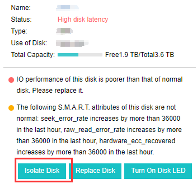
Handling Read-Only Disk
Description
If the hard disk is mounted as read-only due to an abnormality in the hard disk, the write operation on the hard disk will be blocked. Sangfor Virtual Storage will identify the read-only hard disk and isolate it. If it occurs three times within 24 hours, the hard disk is isolated to avoid affecting the customer’s business.
Precautions
- Two node environments do not support isolating read-only hard disks.
- PCIe disks currently do not support handling read-only disks.
- The witness node currently does not support handling read-only disks.
- If the virtual datastore has not been created, handling read-only disks are not supported.
- Hybrid volumes only support handling read-only disks of data disks, not cache disks.
- Data disks in all-flash volumes support handling read-only disks.
- If a disk is newly created/expanded/replaced, handling read-only disks will take effect 30 minutes after the disk is online.
Prerequisites
None.
Steps
Log in to the HCI platform and view the hard disk status on the Storage > Virtual Storage > Physical Disks interface. When a read-only disk fails, the platform automatically isolates the hard disk and generates an alert on the interface.
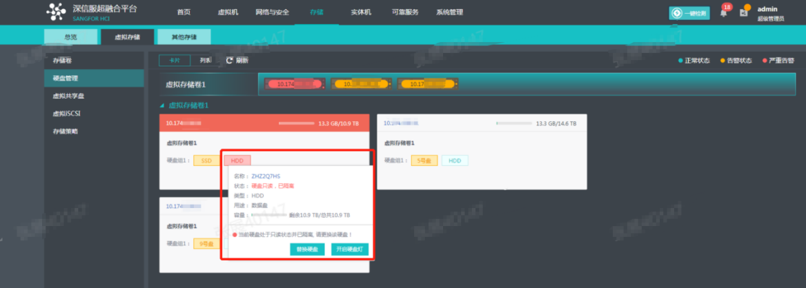
Other Storage Configuration Guide
Adding FC Storage
Description
HCI supports adding FC storage as external storage, allowing the datastore of virtual machines to be placed on FC storage. FC storage is used as external shared storage, and virtual machines whose datastore is in shared storage can implement the HA function.
Precautions
- When adding FC storage to HCI, the volume will be formatted. Before adding, please confirm that other nodes do not use the volume.
- If the FC storage has been added before, it will prompt whether to restore the virtual machine on the FC storage.
- It is recommended that the hosts be configured with two HBA cards, each HBA card is configured with a fiber optical module, and the single-link bandwidth is more than 6GE.
- Not allowed to use external storage that does not support ATS to run production business (verify whether the storage supports the VAAI interface). The external storage needs to support sharing (multiple hosts can access at the same time) and support VAAI features (mainly referring to ATS attributes).
- It is forbidden to shrink the external storage used by HCI.
- It is prohibited to use thin provisioning/dynamic allocation for disk overcommitment on the external storage used by HCI.
- Before adding FC external storage, you need to click Scan for New Disk and then click New.
Prerequisites
- There is an HBA card on the HCI node, which can be connected to the switch of the FC storage.
- The FC storage and switches must be properly configured to map the corresponding volumes to the HCI node.
- The storage must support hardware acceleration or ATS features. Otherwise, none can be added to the HCI platform.
Steps
-
Insert the HBA card into the HCI node and connect it to the FC storage directly through optical fiber or an FC switch.
-
First, check whether the HCI can recognize the HBA card normally. You can select the node in Nodes and enter the Summary page of the relevant node to check the status of the HBA card.
-
Make proper configurations on FC storage and fiber switches, then map the corresponding volumes to all nodes in the HCI cluster.
-
Navigate to Storage > Other Datastore, click New and select FC Storage to add FC storage.
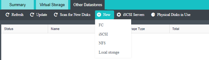
-
Select FC storage and add disks. After adding, you need to configure the accessible nodes as all current nodes in the cluster.
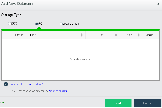
Adding iSCSI Storage
Description
HCI supports adding iSCSI storage as external storage, allowing the datastore of virtual machines to be placed on iSCSI storage. iSCSI is used as external shared storage, and virtual machines whose datastore is shared storage can implement the HA function.
Precautions
- The volume will be formatted when adding an iSCSI virtual datastore to HCI. Before adding, please confirm that other nodes do not use the volume.
- When configuring an iSCSI external storage, it is recommended not to configure the iSCSI alias in the storage configuration.
- Before adding iSCSI external storage, you need to click Scan for New Disk and then click New.
- It is forbidden to use thin provisioning/dynamic allocation for disk overcommitment on the external storage used by HCI.
Prerequisites
- The interface on the HCI node can communicate with iSCSI and the storage server.
- The storage must support hardware acceleration or ATS features. Otherwise, none can be added to the HCI platform.
Steps
-
Configure the IP address of the storage interface on the HCI node so it can communicate with the iSCSI storage server normally.
-
Configure the iSCSI storage and map the LUN to the HCI node. You need to check the IQN of the HCI.
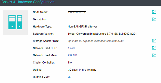
-
Navigate to Storage > Other Datastore in the console, and click iSCSI Server.
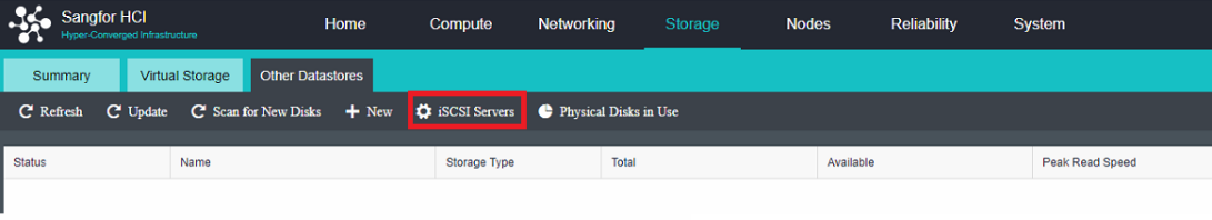
- Add an iSCSI server, and configure the server’s IP address, interface, and related authentication information. After configuration, click Detect Target.
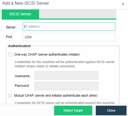
- Click New and select iSCSI.
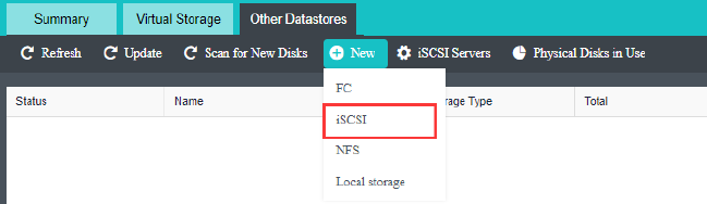
- Select iSCSI, then select the corresponding volume to add. After adding, you need to configure the accessible nodes to be all the nodes in the current cluster.
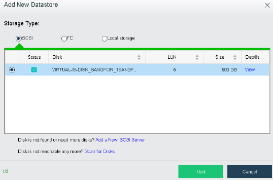
Adding NFS
Description
HCI supports adding NFS as the backup datastore of virtual machines. Virtual machines are backed up to NFS to ensure the data security of virtual machines.
Precautions
- NFS cannot be used as a datastore for virtual machines. It can only use for backup purposes.
- It is forbidden to use the Windows shared drive as an external datastore.
- Before adding NFS storage, you need to click Scan for New Disk and then click New.
Prerequisites
The storage network on the HCI host needs to be able to communicate with NFS storage normally.
Steps
- Navigate to Storage > Other Datastore, click New and click NFS.
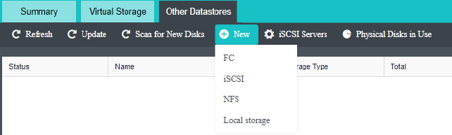
- Configure the name of the NFS storage and the server IP, select the corresponding folder, select the node to be connected, and click OK.
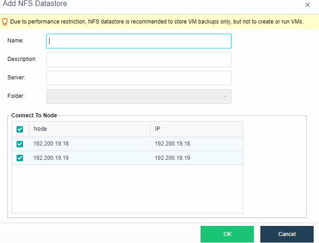
Adding Local Storage
Description
HCI supports adding local storage of disks except for the node system disk or a logical disk after the disks on the server are formed into the RAID as the virtual machine’s datastore.
Precautions
- Adding a disk to local storage will format the disk.
- Before adding local storage, you need to click Scan for New Disks and then click New.
Prerequisites
Free disks on the HCI node must be used for local storage, and the RAID card needs to be configured accordingly.
Steps
- Go to Storage > Other Datastores, click New, and select Local Storage.
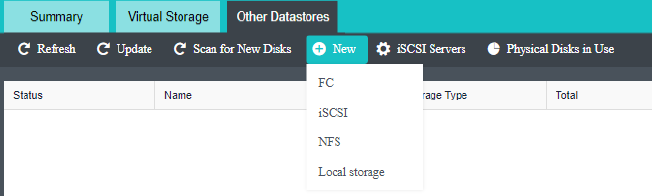
- After selecting the local storage, select the disk to be added, click Next, configure the local storage name, and confirm.
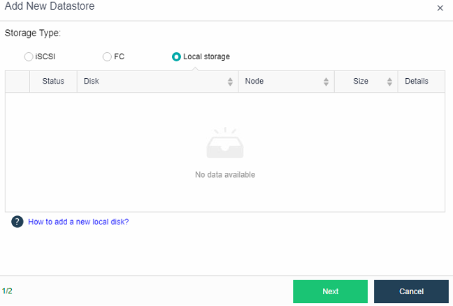
- Fill in the storage name and description, then click OK.
Deleting Storage (High Risk)
Description
Storage needs to be removed from HCI and is no longer available for HCI.
Precautions
- Deleting storage from the HCI will delete the virtual machine whose datastore is the storage from the platform. After the deletion, the virtual machine will start with the None method.
- Both external storage and local storage can be deleted.
Prerequisites
None.
Steps
Go to Storage > Other Datastores, and select the datastore that needs to be deleted. Click on the dropdown menu and select Uninstall.
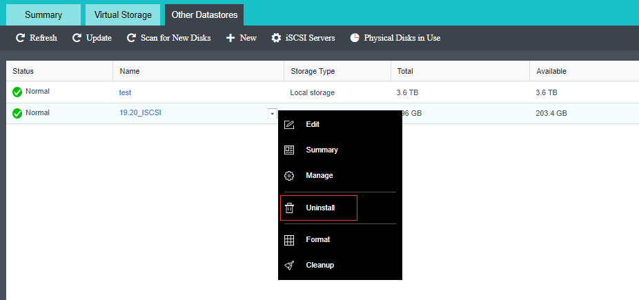
Reliability Configuration Guide
HA Configuration
Description
For virtual machines on shared storage, you can use the HA function. By configuring the detection conditions, when the following failures on the node are detected and persist for a certain period, it will trigger the HA function of the virtual machine to restore operation on another node.
Precautions
-
The failover function is only available for virtual machines with HA checked.
-
Only virtual machines whose datastore is virtual storage or external storage can use the HA option.
-
In the HA scenario of many virtual machines, if the cluster resources are insufficient, it leads to HA failure.
-
After the platform license expires, the virtual machine HA does not work.
-
Do not edit the HA configuration when testing HA.
-
It is recommended for core applications to reserve a certain amount of resource space on some nodes in Reliability > Resource Reservation to ensure that there are enough resources to run the virtual machines for core services when HA occurs.
-
When the management and service communication interfaces are faulty, enabling HA only takes effect for the two-node cluster and does not take work in a three-node or more cluster.
-
When the communication interface is faulty, enabling HA only takes effect in a two-node cluster and does not take effect in a three-node or more cluster.
Prerequisites
HCI cluster consists of multiple nodes.
Steps
- Go to Reliability > HA.
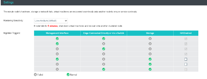
- Enable the scenario you want to implement HA (it is required that the virtual machine on the platform should not be restarted unless in extreme cases, you can disable the two options), and click Save.
Resource Scheduling Configuration
Description
Cluster resource scheduling will schedule cluster resources in a specific scenario. The resources here refer to virtual machines. The scheduling operation is actually migrating virtual machines. We can set CPU and memory thresholds, and if any node exceeds the thresholds, resource scheduling will be triggered, and virtual machines will be scheduled according to the automation level. As a result of scheduling, virtual machines are migrated from nodes with relatively high CPU or memory usage to nodes with relatively low utilization, and the utilization of nodes with excessively high load is reduced below the threshold.
Precautions
None.
Prerequisites
- HCI clusters consist of multiple nodes.
- The virtual machine is stored on external storage or virtual storage.
- The virtual machine running location is configured to be selected automatically.
- The CDP function is not enabled on the virtual machine, the CPU exclusive function is not configured, and the USB mapping is not configured.
Steps
- Go to Reliability > Resource Scheduling.
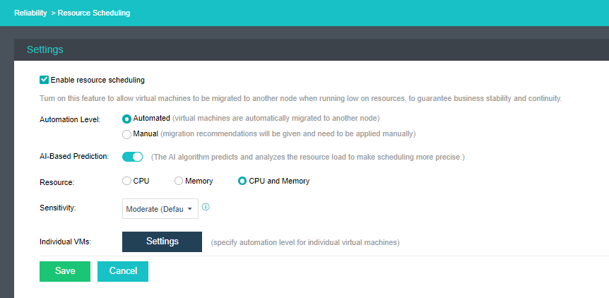
- The user can choose whether to enable AI-Based Prediction. The cluster can perform intelligent DRS scheduling based on the load of the host or virtual machine in the past 7 days to estimate the load for the next 2 days. If this function is enabled, the resource scheduling will use the AI-Based Prediction algorithm, which makes resource scheduling more intelligent.
- Users can set the measurement factors of resource scheduling and choose according to three types of resources: CPU, memory, or CPU and memory. If CPU and memory are selected, the resource scheduling policy will be triggered when any of them reaches the threshold trigger condition.
- Users can set the sensitivity for resource scheduling. Different sensitivities correspond to different node load thresholds. Assuming that Moderate is selected, the node load is greater than 60%, and resource scheduling will be triggered when the node load difference exceeds 20%. For Aggressive sensitivity, when the node load > 50% and the node load difference exceeds 5%, it will trigger resource scheduling.
- The user can choose the automation level (automatic or manual). When you set Automated, a node triggers the threshold and generates recommendations. The recommendations will be automatically executed without manual operation. If you want to generate only recommendations after the node triggers the threshold, no migration occurs, and you need to manually migrate by yourself, select Manual for the Automation level.
- If the scheduling methods of virtual machines require special processing due to certain scenarios, configure the Automation Level for individual virtual machines. There are three modes: Manual, Automated, and Disabled.
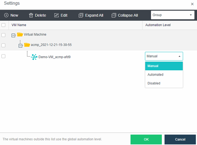
Automated Hot Add Configurations
Description
It is necessary to automatically add CPU and memory resources to the virtual machine during peak business hours to ensure the normal use of business systems.
Precautions
- Automated hot add can only increase resources, not able to automatically reduce them.
- Automated hot-added resources will become invalid after the virtual machine is restarted.
- The maximum value of automated hot add is the configuration size (the original configuration *2). The CPU increases the number of cores in one slot in the original configuration each time, and the memory is 1/8 of the configuration, rounded up, and the unit is GB.
- VM template and virtual network devices do not support automated hot add.
Prerequisites
The operating system needs to support automated hot add. The list of specific operating systems is as follows.
- Operating Systems that support automated hot add of memory.
| Windows | Linux |
|---|---|
| 2008 Ent 32 | RHEL6.5 64bit |
| 2008 Ent 64 | RHEL 7 64bit |
| 2008 DC 32 | ubuntu 14 64bit |
| 2008 DC 64 | CentOS Linux 6 64bit |
| 2008 R2 Ent 64 | CentOS Linux 7 64bit |
| 2008 R2 DC 64 | – |
| 2012 Std | – |
| 2016 Std/Ent/DC 64 | – |
| 2019 Std/Ent/DC 64 | – |
- Operating System that supports automated hot-adding of CPUs.
| Windows | Linux |
|---|---|
| 2008 DC 64 | RHEL6 64bit |
| 2008 R2 DC 64 | RHEL 7 64bit |
| 2012 Std | ubuntu 14 64bit |
| 2012 DC | CentOS Linux 6 64bit |
| 2012 Ent | CentOS Linux 7 64bit |
| 2012 R2 Std/DC 64 | – |
| 2016 Std/Ent/DC 64 | – |
| 2019 Std/Ent/DC 64 | – |
Steps
- Enter the virtual machine editing page, click Processor and check the Enable CPU hot add checkbox.
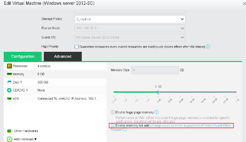
- On the Memory configurations, check the Enable memory hot add checkbox.
- Go to Reliability > Automated Hot Add, check the Enable automated memory/CPU hot add checkbox, and configure Resource, Trigger, and Sensitivity Level.
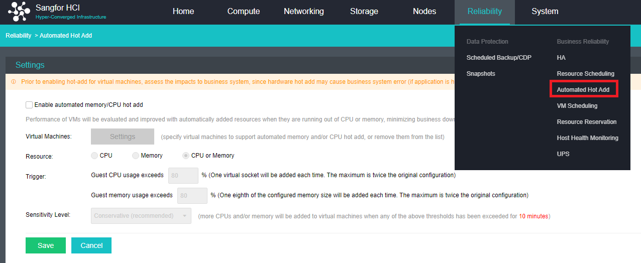
- Configure the virtual machines that require automated hot add and configure the conditions for automated hot add.
Virtual Machine Scheduling Configuration
The virtual machine scheduling policy supports configuring mutual exclusion or aggregation policies for multiple virtual machines and clusters. Through the scheduling policy, you can precisely control the running location of virtual machines to meet the needs of virtual machine service tuning.
VM-VM Affinity
Description
Affinity virtual machines allow multiple virtual machines to be bound and run on a single physical node. For example, virtual machines with frequent business visits or virtual machines in the same business group are bound to the same server to improve business access performance.
Precautions
- A running virtual machine does not support modifying the Running Location configuration.
- After the scheduling policy is created for the running virtual machine, the cloud node needs to be restarted for it to take effect.
Prerequisites
None.
Steps
Enter the Reliability > VM Scheduling interface, and click Create to configure an affinity policy for the virtual machines in the same running location.

VM-VM Anti Affinity
Description
Anti-Affinity virtual machines support running selected virtual machines on different physical nodes. For example, Oracle RAC and other cluster systems are mutually anti-affinity on different physical servers to ensure business reliability.
Precautions
- A running virtual machine does not support modifying the Running Location configuration.
- After the scheduling policy is created for the running virtual machine, you need to restart the virtual machine for it to take effect.
Prerequisites
None.
Steps
Enter the Reliability > VM Scheduling interface, and click Create to configure an affinity policy for the virtual machines in the same running location.
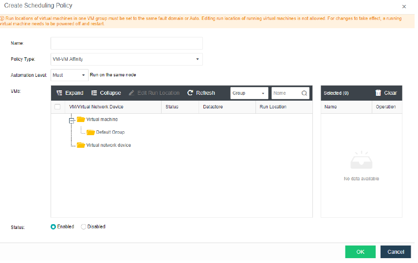
VM Group Anti Affinity
Description
VM Group Anti Affinity supports running multiple selected VM groups on different physical nodes. For example, suppose the three virtual machines of service A and the three virtual machines of service B are configured to be anti-affinity in cloud node groups when the physical node running service A fails. In that case, service B will not be affected, improving service availability.
Precautions
-
The running location must be configured in the same fault domain or automatically selected for the same VM group.
-
A running virtual machine does not support modifying the Running Location configuration.
-
After the scheduling policy is created for the running virtual machine, you need to restart the virtual machine to take effect.
-
The virtual machines in the same VM group will not be in affinity by default, and the affinity policy needs to be configured manually.
Prerequisites
None.
Steps
- Go to the Reliability > VM Scheduling > VM Group interface, and add the virtual machines planned to run in the same location to the VM group.
- On the Reliability > VM Scheduling interface, click Create, select VM Group Anti Affinity for the policy type, select the VM group and click OK.
VM Node Affinity
Description
VM Host Affinity supports running selected VM groups on different physical host groups. For example, run service group A of the active-active service in the main fault domain of the stretched cluster, and run service group B of the active-active service in the secondary fault domain of the stretched cluster to ensure that data and services are active-active at the same time.
Precautions
-
The running location must be configured in the same fault domain or automatically selected for the same VM group.
-
A running virtual machine does not support modifying the Running Location configuration.
-
After the scheduling policy is created for the running virtual machine, you need to restart the virtual machine to take effect.
-
A stretched cluster group hosts in the same fault domain into the same host group by default.
Prerequisites
None.
Steps
-
Go to the Reliability > VM Scheduling > VM Group interface, and add the virtual machines planned to run in the same location to the VM group.
-
Go to the Reliability > VM Scheduling > Node Group interface and add the nodes in the primary and secondary fault domains to the same node group.
-
Select VM Node Affinity for the policy type, fix service A to the primary fault domain, and fix service B to the secondary fault domain.
Resource Reservation Configuration
Description
By configuring resource reservation, the memory of the node can be reserved. When a virtual machine fails HA, this part of the reserved resources can be used preferentially for recovery.
Precautions
None.
Prerequisites
- HCI cluster consists of multiple clusters.
- The virtual machine is stored on external storage or virtual storage.
- The virtual machine running location is configured to be selected automatically.
Steps
- Go to Reliability > Resource Reservation.
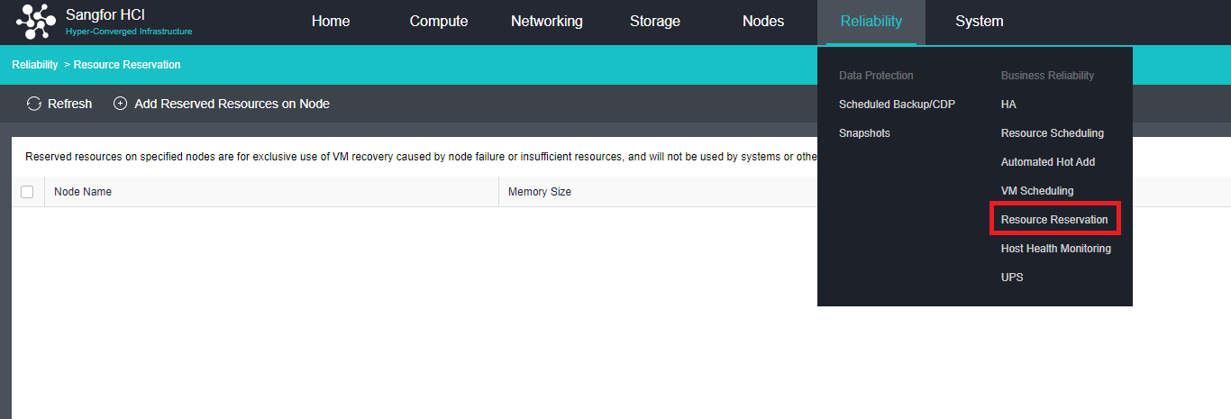
- Click Add Reserved Resources on Node to set reserved resources according to the service’s actual usage and the node’s resources.
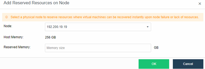
Host Health Monitoring
Description
The HCI platform can automatically identify and display hosts’ health, and for hosts that have been judged to be unhealthy, they will be downgraded when the virtual machine is powered on or HA is performed. For scenarios such as cluster capacity expansion and host replacement, hardware status is checked to avoid frequent node downtime or suspended systems due to hardware failures and to reduce business risks caused by hardware problems.
Precautions
- Only supports the identification of the suspended host due to hardware failures.
- Suppose it is suspended caused of a memory failure when the host is turned on and restarted. In that case, the host will not be automatically released if the faulty memory position is not accessed. To remove the unhealthy host manually, you can click Remove to remove the host from the list after resolving the issue.
Prerequisites
None.
Steps
- Enter the Reliability > Host Health Monitoring interface. If the physical host is automatically identified as unhealthy, it will be displayed in the Unhealthy Hosts list.
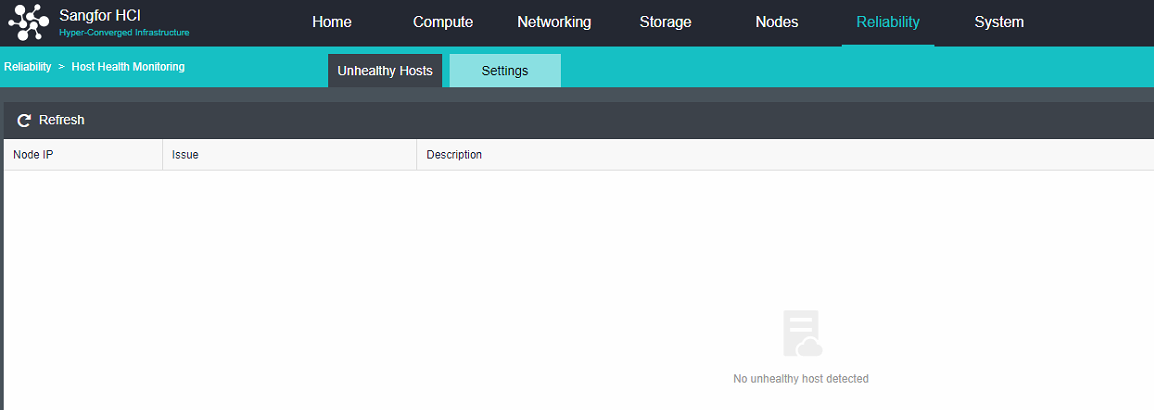
- Enter the Settings interface to perform health detection-related settings.
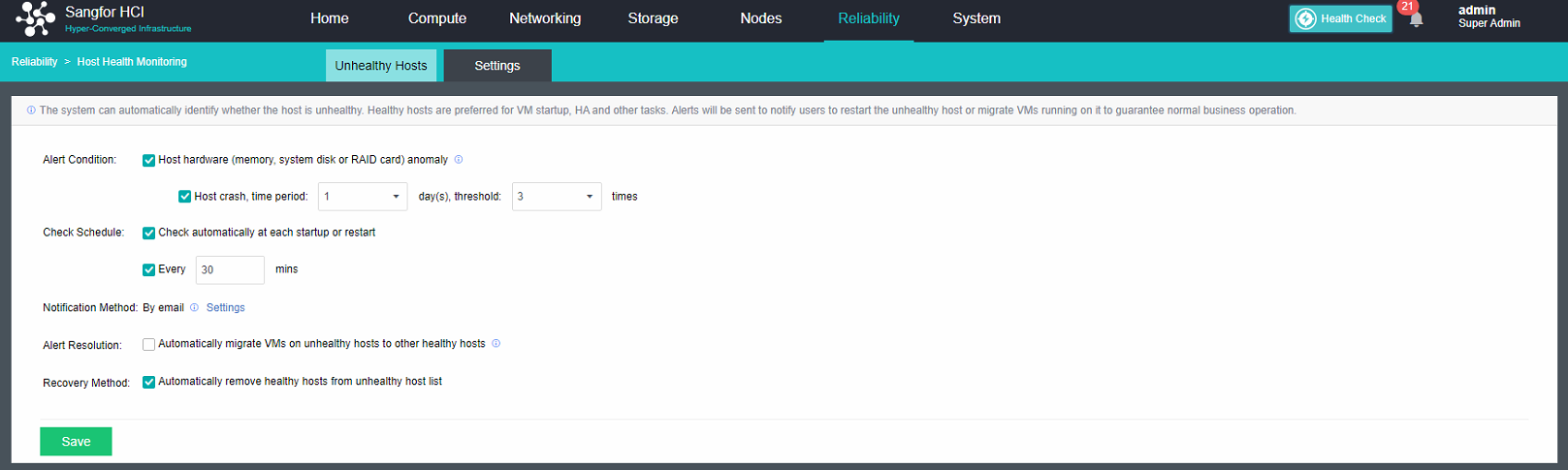
Memory ECC Isolation
Memory ECC Isolation
Description
When a production or platform process runs in a memory location with an ECC error, the kernel will receive the ECC error message reported by the memory. Sangfor HCI memory isolation mechanism will try to isolate the memory space to prevent subsequent business or platform processes from using it again.
Precautions
The memory ECC function requires the server CPU to support the MCE function. If hardware confirmation is involved, please contact Sangfor technical support.
Prerequisites
None.
Steps
- Log in to the HCI platform. When ECC memory isolation occurs, an alert prompt will appear on the interface, prompting " The node (XX.XX.XX.XX)’s RAM stick (CPUx-MCx-CHANx-DIMMx) contains too many correctable ECC errors that could not be isolated. ".

- When the isolation ratio of a single memory module exceeds 10%, a general alert will be generated.
- When the isolation ratio of a single memory module exceeds 25%, there is very little available memory, and an emergency alert will be generated.
- When an alert appears on the platform, it is recommended to contact the service provider to replace the memory module. When replacing a memory module, please turn on the node maintenance mode of the corresponding node before replacing it.
Notice:
The memory module address in the alert prompt is the logical address of the memory module. You need to refer to the memory layout diagram of the server to replace the memory module.
Memory UE Error Isolation
Description
When the fault memory space of ECC memory UE is located in the application layer process, the physical node will not go down but only kill the process. This is because the memory isolation mechanism will try to isolate the memory space. The physical node will be down when the wrong memory space of ECC memory UE is located in the kernel during the layering process. After restarting, the HCI platform will receive an ECC UE error message. The memory isolation mechanism will try to isolate the memory space to prevent subsequent services or platform processes from using the memory space again.
Precautions
The memory UE isolation function has related hardware requirements:
- CPU architecture model must be Purley platform.
- The BIOS version requirement is BIOS RC code 610D02 (BKC: Purley BKC IPU 2020.2) and above.
- The server’s firmware cannot shield the scanned UE/CE and UE/CE errors triggered by user mode access.
- BIOS function setting switch: System memory poison > Enabled (UE recovery function, required), and Enable patrol scrub (memory hardware scan function, required), Patrol Scrub Error Downgrade (error downgrade function, optional).
Notice:
For confirmation of hardware information, you can contact Sangfor technical support to obtain it.
Prerequisites
None.
Steps
Log in to the HCI platform. When ECC memory isolation occurs, an alert prompt will appear on the interface, prompting, "The node (XX.XX.XX.XX)’s RAM stick (CPUx-MCx-CHANx-DIMMx) contains too many uncorrectable ECC errors that could not be isolated. ".
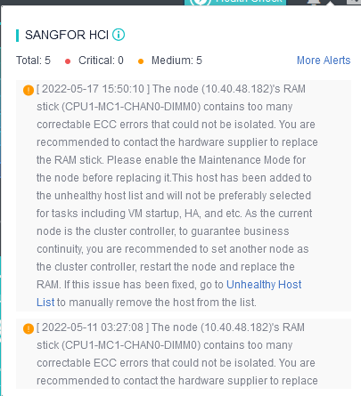
UPS
Description
The HCI node can be associated with the UPS power supply. When the mains line fails, it supports setting different shutdown thresholds for virtual machines of different importance levels. By default, when the remaining power of the UPS drops to 80%, the non-core virtual machines are shut down. Likewise, when the remaining power of the UPS reaches 30%, the core virtual machines are shut down (users can set the trigger threshold according to their own needs) to achieve the effect of protecting services.
Prerequisites
The platform can only detect the network connection status between the UPS and the host. Please ensure that the node’s power supply is connected to the associated UPS. Also, ensure that the physical switch connecting the node and the UPS is powered.
Precautions
-
When the physical host is powered by both the utility power and the UPS power supply (as shown in the figure), it is recommended not to enable the shutdown policy to prevent the linkage shutdown mechanism from being triggered when the power supply connected to the UPS is powered off.
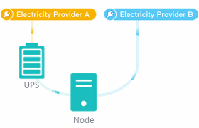
-
After the shutdown policy is enabled, the virtual machine running on the associated node will be shut down when the UPS’s battery power is lower than the set threshold. Still, the physical node will not be shut down.
-
When the node is associated with multiple UPSs, the associated UPS must be powered by batteries simultaneously. Therefore, the linkage shutdown mechanism will be triggered when the power is less than the set threshold.
-
If Resource Scheduling is enabled, virtual machines are not scheduled to physical nodes powered by UPS batteries.
-
If the UPS is already offline on the page, the platform will not execute the coordinated shutdown policy for the host associated with the UPS.
Steps
- Go to Reliability > UPS and click Add UPS. Enter the name, IP address, version, and read community, select the appropriate OID and click OK to add.
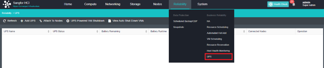
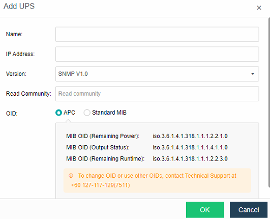
- After the UPS power supply is added to the HCI, click Attach to Nodes to associate the UPS with the node.
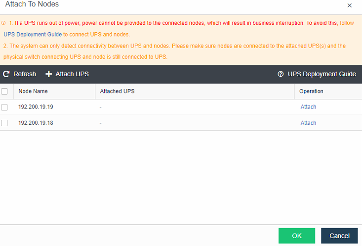
- Click UPS-Powered VM Shutdown to enable or disable the UPS coordinated shutdown policy, make specific policy settings, set the first and second stage threshold, and select the virtual machine as the core virtual machine.
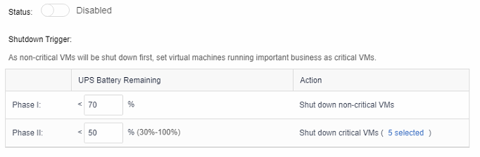
- Click View Auto Shut-Down VMs to view which VM had been shut down automatically. The virtual machine can be powered on after disabling the UPS linkage policy.
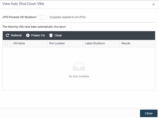
RAID Card Troubleshooting
Description
When the RAID card of a node in the HCI cluster is abnormal (for example, the card runs slowly), the storage performance of the cluster will be degraded or even cause the production/storage to fail. The RAID status anomaly detection function can detect the abnormality of the RAID card, notify the administrator in time, and isolate the physical node corresponding to the RAID card when the card is stuck to avoid affecting the stability of the entire cluster and interrupting storage as the whole or cluster production.
Precautions
- The node must configure IPMI. Otherwise, the node cannot be recovered remotely after being isolated.
- Alert prompts might fails if the RAID card has failed.
- In a two-node Virtual Storage cluster (in the scenario where no quorum node is configured), the virtual machine may experience split-brain when one of the nodes has isolated.
Prerequisites
None
Steps
- Login to the HCI WebUI console and navigate to System > Advanced. Under Node, enable the RAID Card Status Check.
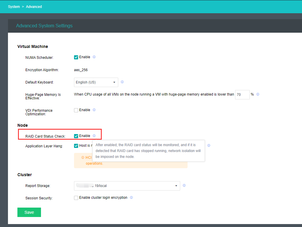
- When the RAID card is at fault, an alert will be prompted: RAID card status of node (xxx.xxx.xxx.xxx) is abnormal. Virtual Machines on the node will automatically HA or failover to another node to avoid cluster production interruption.
Virtual Machine Disaster Recovery and Backup
Precautions
- Enable the scheduled backup policy for virtual machines required for data protection, and back them up on external storage.
- It is recommended to use enterprise-class block and NAS storage.
- It is forbidden to use open-source software to install free NAS on the server for backup.
- Using iSCSI/NAS backup in the network below the Gigabit environment is forbidden.
- Mounting iSCSI/NAS across the WAN for backup is forbidden.
- Not allowed to use Windows file sharing for backup purposes.
- Core business backup: The core VM must be backed up, and it is recommended to back up once a day (use HCI’s backup or the customer’s backup software but must have a backup).
- Backup target storage space: It is recommended that the backup space utilization rate be lower than 80%.
- Virtual machine backup failure: If the backup fails, please contact Sangfor technical support directly.
Fast Backup and Recovery
Manually Backup
Description
This section guides administrators in performing manual backups of virtual machines.
Precautions
- The virtual machine can be backed up when powered on or off.
- The first backup is a full backup, and the backup to the same datastore is an incremental backup.
- When the backup repository is virtual storage, FC storage, or iSCSI storage, it supports quickly pulling up the virtual machine when restoring the backup.
- After upgrading from HCI5.0 to HCI5.3, trigger the backup for the first time, the old backup will be moved to the recycle bin, and a new backup will be made. After 30 days, the old backups in the Recycle Bin will be cleared, but new backups will be available. If there is a need for long-term retention of old backups, contact technical support for processing.
Prerequisites
A backup datastore has been configured (a third-party backup repository is recommended).
Steps
- Navigate to Compute, move to the selected VM and click More > Back Up.
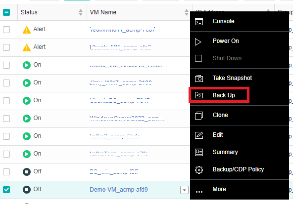
- Enter the Create Backup page, input a custom description, and select the Destination Datastore.
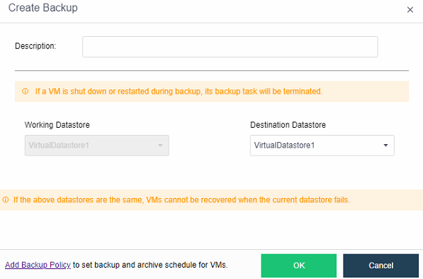
- Click OK, the virtual machine enters the backup state, and the virtual machine completes the backup after a few minutes.
- You can view the created backup information in the VM Backup&CDP Policy section.
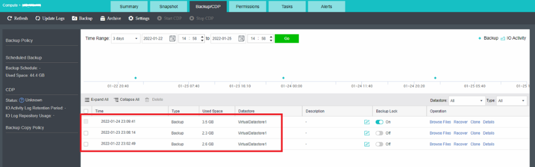
- Backup merge speed limit: Enter the backup merge speed limit configuration page from the settings option in Reliability > Scheduled Backup/CDP > Settings.
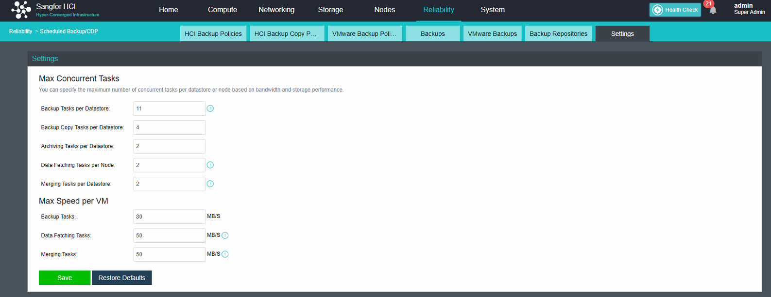
- The maximum number of concurrent backup and merge speed limits can be configured to 16, and the maximum speed limit can be up to 300MB/S.
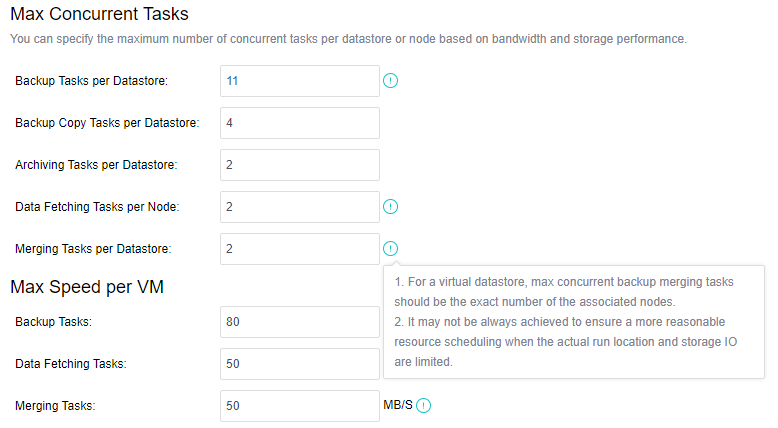
Backup Policy Configuration
Description
Guide administrators to configure automatic backup policies in the scenario of automatic virtual machine backup. The backup cleanup policy setting is more flexible, and the backup retention period can be set up to 100 years. Supports setting up regular full backups on a monthly basis. Supports automatic archiving of backup files to secondary storage and restores virtual machines from archived files.
Precautions
- The virtual machine can be backed up when powered on or off.
- The first backup is a full backup. Other backups within the backup retention period are incremental backups.
- Only one full backup is retained in each backup retention period, and the system will automatically merge the first full backup and multiple incremental backups into a new full backup at the start of the next backup retention period.
- The virtual machine can be quickly pulled up during backup and recovery when the backup repository is virtual storage, FC storage, or iSCSI storage.
- Each virtual machine can only be added to one backup policy.
- When compression is enabled for backup archives, the compressed archive time will increase by three times or more than the uncompressed case, and the data sorting time after recovery will increase by about three times or more than the uncompressed case. It is recommended to choose whether to compress according to the actual situation.
Prerequisites
- A third-party backup repository has been configured (it is recommended to configure a third-party backup repository).
- When using the archive function, a separate archive repository is required, and the archive needs to be added to the backup repositories before configuring the archive. The Windows shared directory and the storage in the same location as the backup location cannot be selected for the archive storage.
Steps
-
Go to Reliability > Scheduled Backup/CDP and enter virtual machine backup configurations.
-
Select Regular Backup for the backup method, select New Backup Policy for the backup policy, enter the backup policy setting page, and set the backup schedule, backup date, and duration. Select whether to select Enable regular full backup according to actual needs.
Notice:
The priority of regular full backup tasks is higher than that of common backup tasks.
Even if no incremental data is generated, the virtual machine will be backed up according to the regular full backup policy and will not be canceled by timeout.
Enabling regular full backup will consume more storage resources and may take a long time to complete. During this period, incremental backup is not executable. However, it can reduce the length of the backup chain of the virtual machine and improve the IO performance during the fetch data stage after the virtual machine is restored.
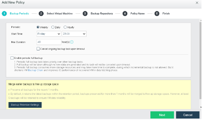
- Click Next.
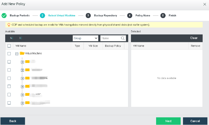
- Select the corresponding backup location. If the cluster is configured with an archive repository, you can select Archive backups to other datastores and click Next.
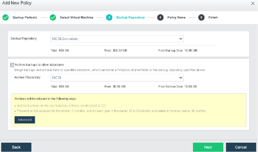
- Fill in the backup policy name and description, and click Next.

- Confirm the configuration of the backup policy. If there is an error, you can go back and click Previous to modify it step by step. After confirming there is no problem, click OK to make the scheduled backup policy take effect.
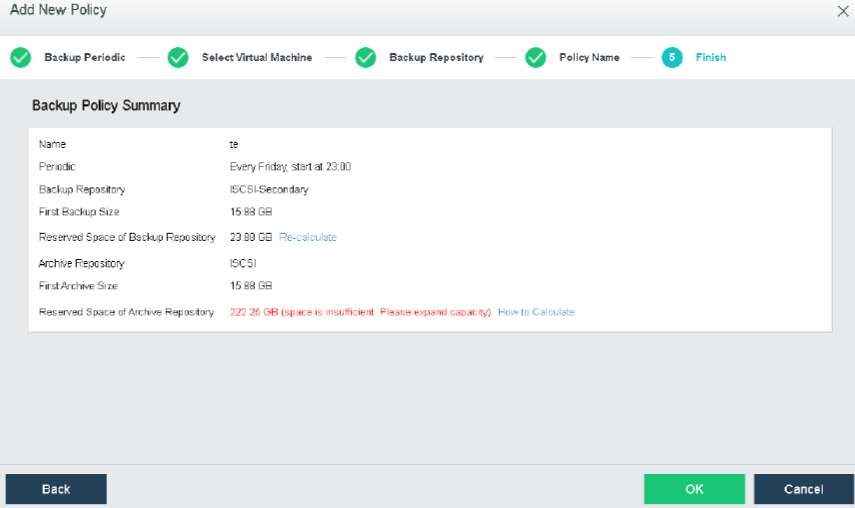
Backup Recovery
Description
This section guides the administrator in restoring the backup virtual machine.
Precautions
None.
Prerequisites
- The virtual machine that needs to be restored has backup files before the operation.
- Manual recovery is not supported for backup files moved to the recycle bin.
Precautions
- After restoring the virtual machine (whether a new one or overwriting the original virtual machine), the disk allocation mode becomes thin provisioning, leading to performance degradation. You can manually go to Compute and move to the selected Virtual Machine. Then, click More > Edit > Disk to adjust the settings to pre-allocating.
Steps
-
On the Compute page, move to the selected virtual machine and click More.
-
Click Backups to find the backup file of the virtual machine.
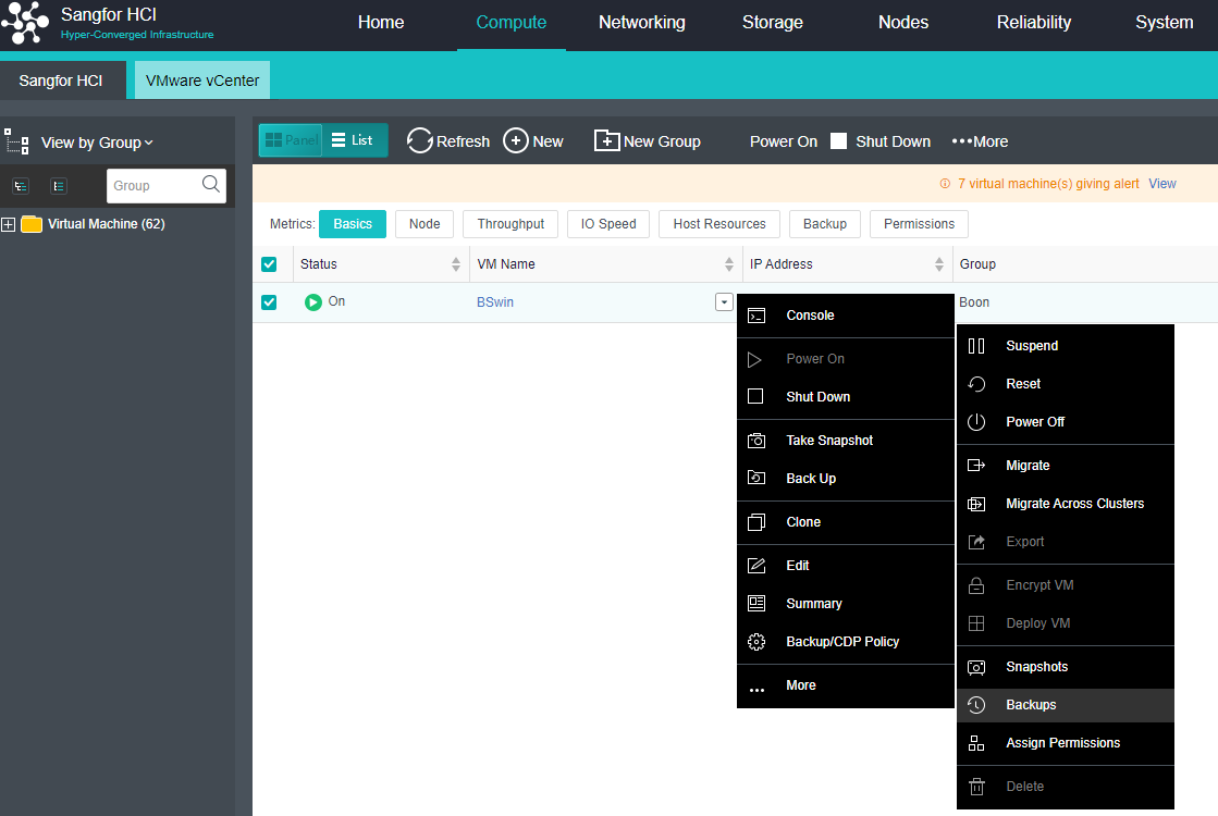
- Click Recover to restore the corresponding backup file. You can choose to Create a new one or Overwrite the existing one to restore.
CDP Backup and Recovery
Backup Policy
Description
This section guides administrators in configuring CDP policies in automatic virtual machine backup scenarios. The HCI platform provides a virtual machine-level Continuous Data Protection (CDP) solution, which records every IO of important services. It can be restored to a complete service server in seconds and quickly retrieve the services at any IO moment in the past. System Files.
Precautions
- The formula for calculating the maximum space used by IO logs: average write IO speed 3600 (1 hour and seconds) retention time (hours) / 1024 = GB. For example, if the average writes IO speed of the business system is 10MB/s, the retention time is 1 day, and the interval is 1 hour, the maximum space used by the IO log is 10 3600 24 / 1024 = 844 GB.
- It is recommended to start with three HCI cluster nodes.
- CDP protection of physical disks mapped in virtual machines is not supported.
- Only the destination storage of CDP is supported to be configured on iSCSI, FC, and aSAN.
- Only NTFS and FAT32 file systems support file retrieval functions, and the Linux system does not support file retrieval operations.
- Using the CDP function, if the backup and I/O logs are placed on the external storage and because the I/O logs and backups occupy space, the I/O logs cannot be stored in time, and the I/O log buffer is exhausted. Resulting in CDP interruption. It is recommended not to place backups and logs in the same storage.
Prerequisites
A third-party backup repository has been configured.
Steps
- Navigate to Compute, move to the selected VM and click More.
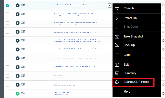
- Click Backup/CDP Policy to enter the VM backup page.
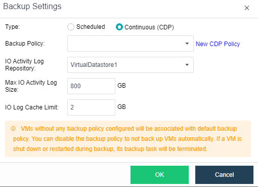
- Click Settings, and set the IO Activity Log Retention Period, IO Activity Logging Interval, Backup Schedule, and Backup Retention Period.
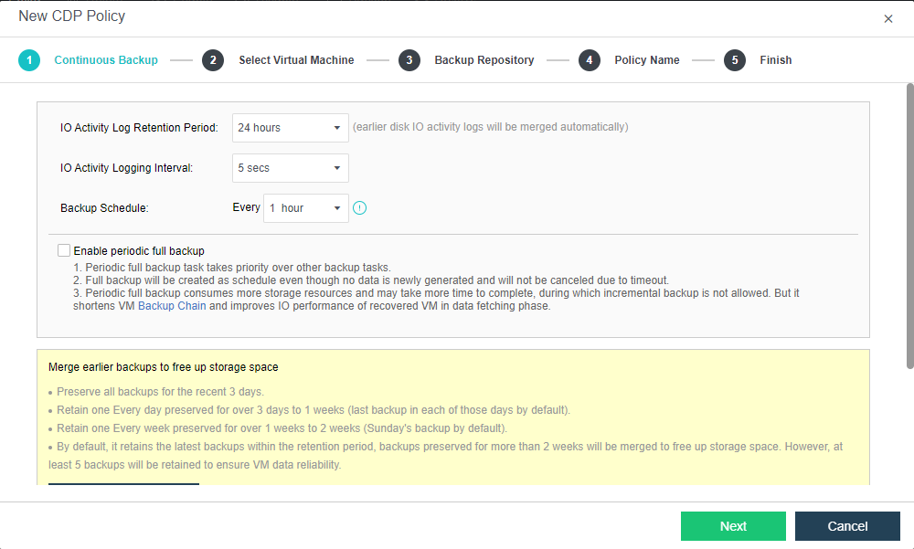
- Select the VM to be configured with the CDP policy.
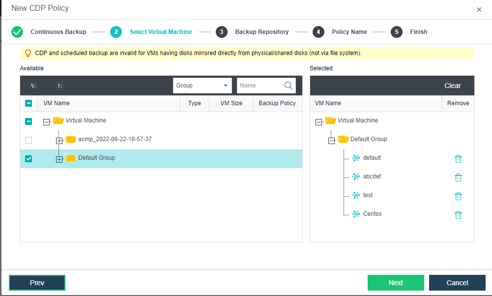
- Select the Backup Repository and IO Activity Log Repository.
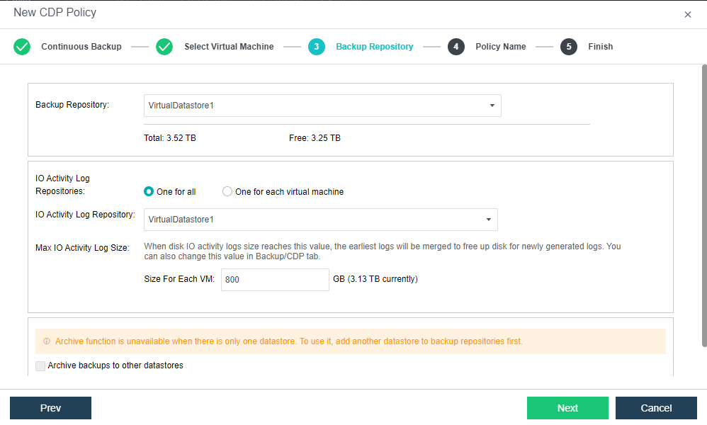
- Fill in the policy name and description (optional).
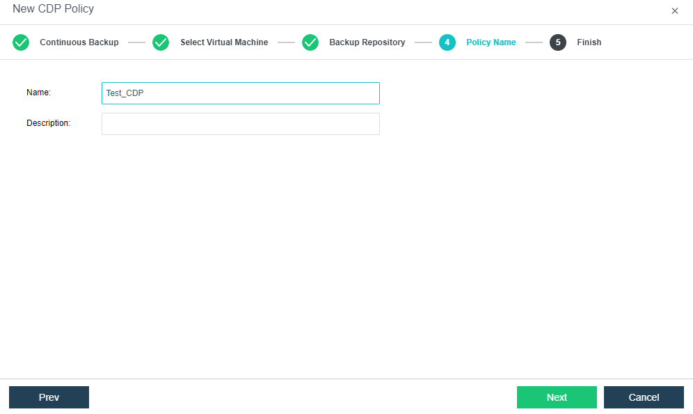
- Confirm the configuration of the CDP policy. If there is an error, you can go back and click Prev to modify it step by step. After confirming there is no problem, click OK to make the scheduled backup policy take effect.
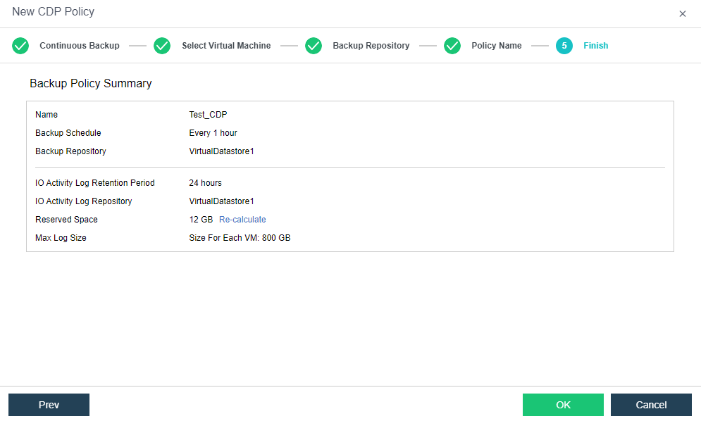
CDP Recover System
Description
This section guides the administrator in restoring the backup file. CDP supports recording every IO of the business system and restoring the business system state 5 seconds ago.
Precautions
- Supports power on the virtual machine quickly when restoring the backup.
- After restoring the virtual machine (whether a new one or overwriting the original virtual machine), the disk allocation mode becomes thin provisioning, leading to performance degradation. You can manually go to Compute and move to the selected Virtual Machine. Then, click More > Edit > Disk to adjust the settings to pre-allocating.
Prerequisites
The virtual machine that needs to be backed up has a CDP backup file before the operation.
Steps
- On the Compute page, click the virtual machine name in the virtual machine list to enter the virtual machine details status page.
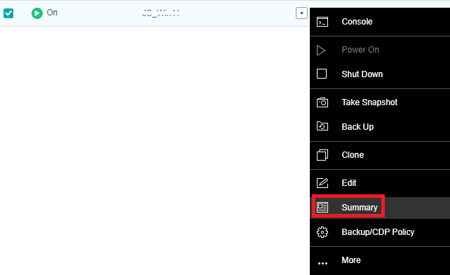
- Click Backup/CDP to find the backup file point of the virtual machine. Then, click Browse File of the selected Time.
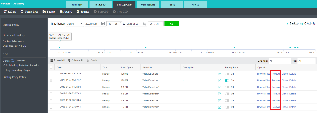
- Click Recover to restore the corresponding backup file. You can choose to Create a new one or Overwrite the existing one to restore.
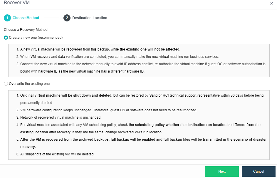
File Recovery
Description
This section guides administrators in browsing and downloading backup files.
Precautions
- Currently only supports Windows NTFS, FAT32 file system format and Linux system ext2, ext3, ext4, xfs file format to retrieve files.
- The None method supports special characters in package_name, such as %, & is the file name.
- When the backup of the virtual machine is stored in sffs, the soft link file of the virtual machine is linked to /proc, and file download is not supported in the /run directory.
- Downloading is not supported when the file to be downloaded in the virtual machine is larger than 5GB.
- When the virtual machine uses a physical disk, the physical disk does not support file browsing.
Prerequisites
A virtual machine needs to browse or download files that have been backed up before the operation.
Steps
- On the Compute page, click the virtual machine name in the virtual machine list to enter the virtual machine details status page.

- Click Backup/CDP to find the backup file point of the virtual machine. Then, click Browse File of the selected Time.
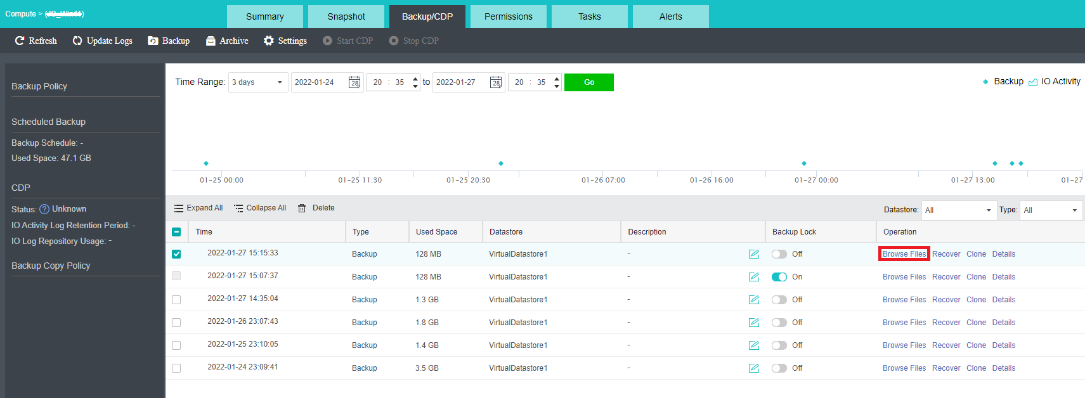
- Click Recover File, and the following message box will pop up. Select OK.
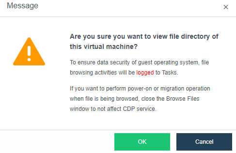
- You can see the download page of Recover File. You can find the file you want to download by searching for the download path of the file or file name. Then, click Download File.
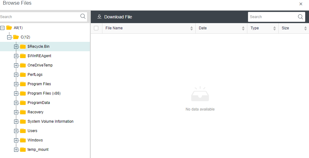
Backup Management
Description
This section guides administrators in managing backup files, repositories, and policies.
Precautions
None.
Prerequisites
None.
Steps
HCI Backup Policies
Description
This section guides administrators in creating and managing backup policies on the HCI platform.
Precautions
None.
Prerequisites
None.
Steps
-
Navigate to Reliability > Scheduled Backup/CDP.
-
In HCI Backup Policies, enable or disable the current backup policy. You can also add, delete, modify, and check the existing backup policies.
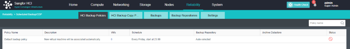
HCI Backup Copy Policies
Description
This section guides administrators in creating and managing backup replication policies.
Precautions
- The destination storage for backup replication does not support local storage.
- The source and destination storage of backup replication cannot be the same.
Prerequisites
None.
Steps
-
Navigate to Reliability > Scheduled Backup/CDP.
-
In HCI Backup Copy Policies, enable or disable the current backup and replication policy. You can also add, delete, modify, and check the existing backup and replication policies.
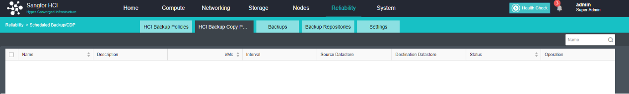
VMware Backup Policy
Description
This section guides administrators in creating and managing VMware backup policies.
Precautions
None.
Prerequisites
None.
Steps
- Navigate to Reliability > Scheduled Backup/CDP.
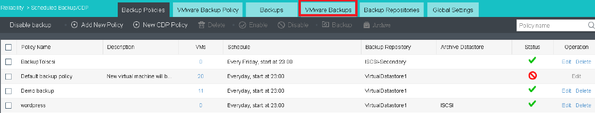
HCI Backups
Description
It is used to manage the virtual machine backup files in the cluster. The backup files can be used to restore the virtual machines or copy the backup files.
Precautions
None.
Prerequisites
None.
Steps
-
Navigate to Reliability > Scheduled Backup/CDP.
-
View the backup file of the virtual machine in the current HCI platform in Backups.
-
Select the virtual machine to be operated and click Recover.
-
Select the virtual machine recovery method and click Next.
-
Select the restore backup point and destination location of the virtual machine, and click OK to complete the restore.
VMware Backup File
Description
It is used to manage the virtual machine backup files on VMware managed in the cluster. The backup files can be used to restore virtual machines or copy the backup files.
Precautions
None.
Prerequisites
None.
Steps
- Navigate to Reliability > Scheduled Backup/CDP > VMware Backups.
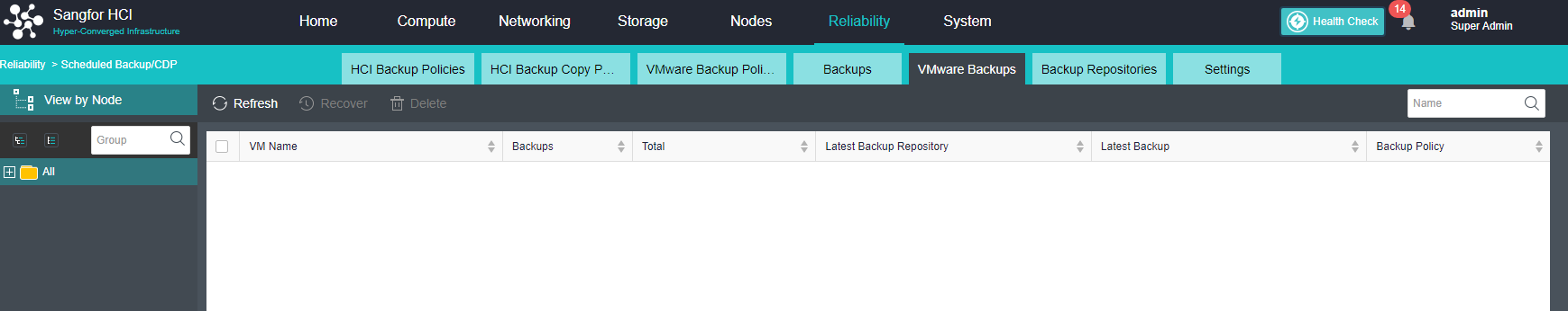
Backup Repository
Description
The backup repositories refer to the backup repository system that stores the current virtual machine files. It is recommended to use aSAN distributed storage for the backup repositories. Still, you need to specify the used capacity space so that the distributed storage can manage it in isolation. Click the backup space with the mouse to set the backup space. Storage media can be added to the backup resource pool.
Precautions
None.
Prerequisites
None.
Steps
-
Navigate to Reliability > Scheduled Backup/CDP.
-
View the current backup capacity usage in Backup Repositories.
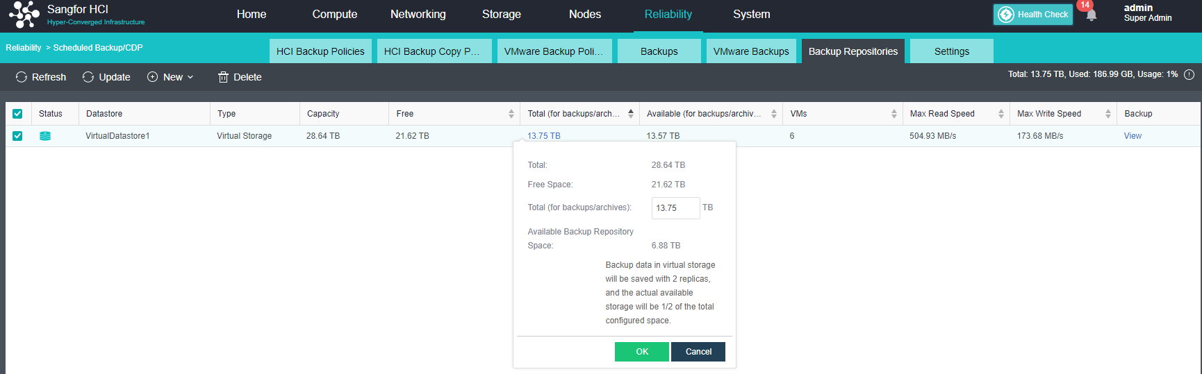
- Click New > Add Datastore to Backup Repositories.

- Select the storage that needs to be added to the backup repositories, set the size of the space for backup, and click OK to complete the resource pool addition.
Settings
Description
Backup tasks can be configured.
-
Backup Tasks per Datastore: Set the maximum number of concurrent tasks when storing backups.
-
Backup Copy Tasks per Datastore: Set the maximum number of concurrent tasks during storage backup copy.
-
Archiving Tasks per Datastore: Set the maximum number of concurrent tasks when storing archives.
-
Data Fetching Tasks per Node: Set the maximum number of concurrent data sorting tasks for each node.
-
Merging Tasks per Datastore: Set the maximum number of concurrent tasks during storage consolidation. During automatic consolidation of backup points, if the storage where the virtual machine is located is a virtual datastore, the maximum number of concurrent tasks is the number of nodes of the virtual datastore.
-
Backup Tasks: Limit the maximum backup speed during virtual machine backup.
-
Data Fetching Tasks: Limit the maximum data collation speed of each node. For virtual machines that are quickly recovered, the data collation rate of the virtual machine will be limited before the lightning icon disappears not to affect the virtual machine’s performance.
-
Merging Tasks: Limit the maximum speed of virtual machine data merging. When set to 0, there is no limit.
Precautions
None.
Prerequisites
None.
Steps
-
Navigate to Reliability > Scheduled Backup/CDP.
-
In Settings, you can adjust the concurrent number and speed of backup, restore, and merge tasks for each storage.
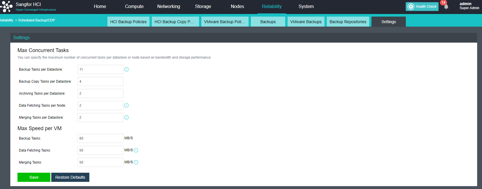
aSecurity Configuration Guide
Sangfor aSecurity (aSEC) builds a unified security platform on the cloud based on unified security policies and security management. It provides targeted protection for different businesses based on accurate asset identification. Security capabilities are automatically enabled without deployment and are deeply integrated with platform capabilities.
Overview of Platform Security Status
Description
The dashboard page of the aSecurity center displays overall platform security information, including whether the virtual machine has security protection enabled, the number of pending events and vulnerabilities to be handled, the number of security events that the aSecurity center has automatically handled since its first deployed, and an overview of security trend over last 30 days.
Prerequisites
None.
Precautions
Auto-detection events will be updated daily at 00:00. Real-time updates are currently not supported.
Steps
- Navigate to aSecurity > select Dashboard to enter the dashboard page. The dashboard shows an overview of security information which includes the total number of virtual machines in the platform, the number of virtual machines with security protection enabled, the number of virtual machines with security events detected, the number of virtual machines being compromised, and the number of virtual machines are unprotected or didn’t enable protection. Click the corresponding number to redirect to the virtual machine security list to view the details.
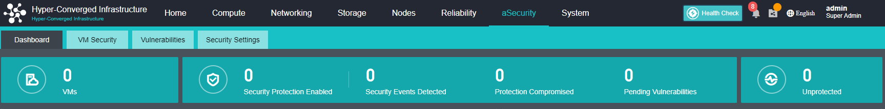
- Pending Events shows the number of security events that have not been handled, including the number of Brute-Force Attacks, WebShell Backdoors, Cryptomining, and Ransomware.
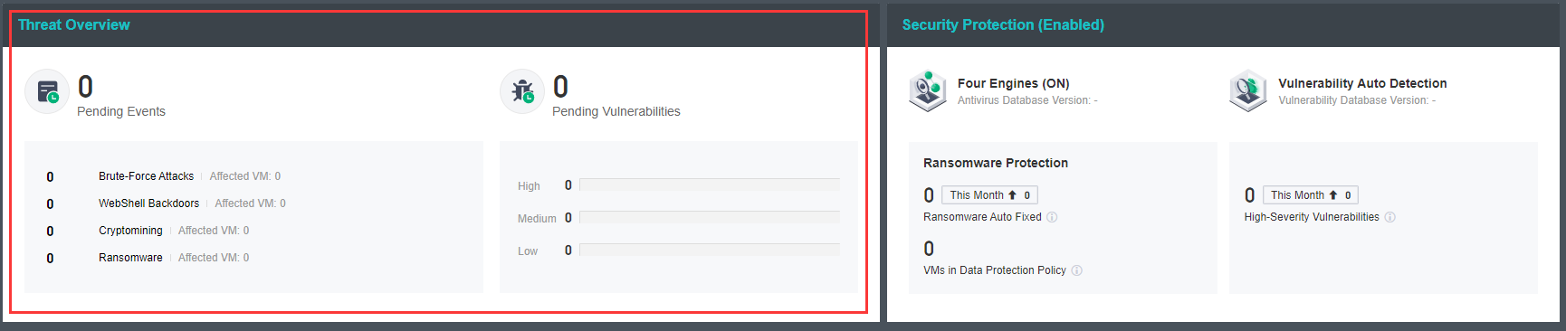
- Security Protection utilizes the four major detection engines: Sangfor Engine Zero, Gene Analysis Engine, Behavioral Analysis Engine, and Cloud-Based Engine for vulnerability auto-detection and handling virtual machines’ security events.
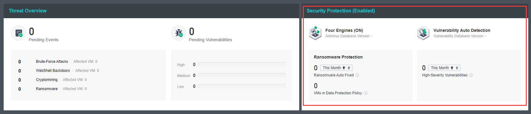
- Security Event Overview shows the security events and overview of all thread types in the last 30 days and supports the view of vulnerabilities based on severity.
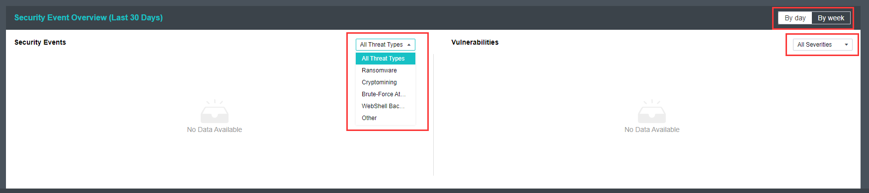
VM Security
-
Sangfor aSecurity supports unified asset management and displays all virtual machines on the HCI platform, as well as basic information and security information of virtual machines for ease and comprehensive management.
-
Sangfor aSecurity supports issuing virus or vulnerability scan tasks to specific virtual machines and provides virus operation policies: fix, trust, restore, untrust, and ignore.
-
Sangfor aSecurity supports one-click processing of security events and provides full-stack guided processing of security events from network isolation, snapshots, and virus processing.
-
Sangfor aSecurity provides ransomware recovery that supports network recovery from ransomware isolation and enables fast and safe business recovery without expert intervention.
Asset Management
Description
Asset management supports the automatic acquisition of virtual machines’ basic information and security events, including security status, running status, virtual machine name, IP address, operating system, application, and security events.
Prerequisites
None.
Precautions
- There are time intervals for asset information reporting. The basic information reporting interval is 1 minute, the security information reporting interval is 5 minutes, and the application information reporting interval is 4 hours.
- The virtual machine list is sorted by security status by default. The sorting policy is Protection Compromised > High > Medium > Low > Protection Off > Unprotected > Protected. When the security status is the same, it will sort by application information Database > Web > Unidentified Application.
Steps
- Navigate to aSecurity > select VM security to enter the VM security page. It supports filtering based on different events and statuses for asset management.
-
Ransomware Detected: The list of virtual machines not handled by ransomware detected.
-
Protection Compromised: The list of virtual machines where security status is protection compromise. When a virtual machine’s security protection capabilities have been maliciously compromised, the virtual machine’s security status will be displayed as Protection Compromised.
-
Security Events Detected: The list of virtual machines that have not been handled by security events detected.
-
Unprotected: The list of virtual machines where security protection is disabled.
-
Quarantined: The list of virtual machines being quarantined.
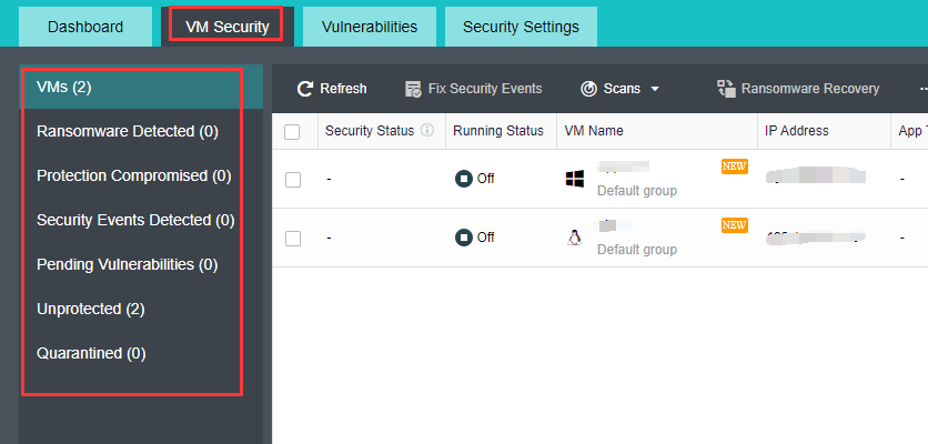
- Under aSecurity > VM Security > VMs page, you can view the running status and security event of all the virtual machines in the HCI platform.
- Security status includes protection compromised, high, medium, low, protection off, unprotected, and protected.
Protection Compromised: VMs whose security protection capabilities have been maliciously compromised, usually caused by ransomware attacks.
High: VMs with high-threat viruses or security risks.
Medium: VMs with medium-threat viruses, brute-force attacks, or security risks.
Low: VMs with low-threat viruses or security risks.
Protection OFF: The security agent is offline, possibly because the network connection encounters an error or the VM or security agent is being started.
Unprotected: VMs with security protection disabled.
Protected: VM with security protection enabled.
- Running status includes On, Suspended, and Off.
- Security events include Ransomware, Worm, Trojans, Infectious Viruses, Cryptomining, Brute-Force Attacks, WebShell BackDoor, Others, and No Security Events.
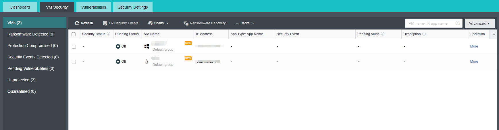
- Click the Advanced button to filter the list of virtual machines according to different categories.
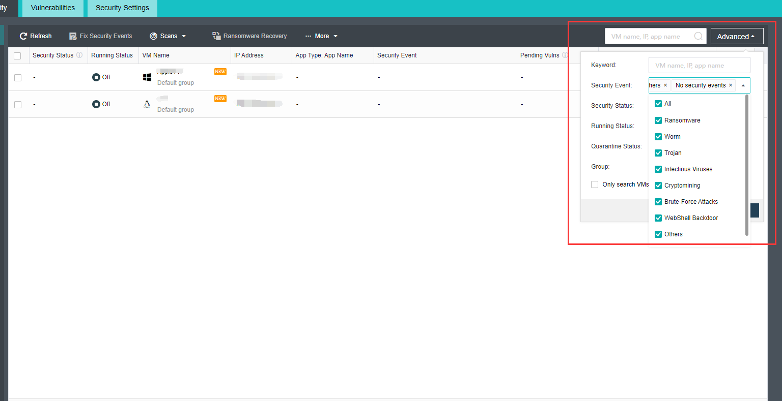
Virus or Vulnerability Scan
Description
Sangfor aSecurity utilizes the four major detection engines: Sangfor Engine Zero, Gene Analysis Engine, Behavioral Analysis Engine, and Cloud-Based Engine for virus or vulnerability scan toward virtual machines and executes security events when viruses or vulnerabilities are detected.
Prerequisites
None.
Precautions
- Up to 100 virtual machines can be selected for virus scanning.
- Only the scan records of the past 30 days are retained in the virus or vulnerability scan history.
- Virus or vulnerability scans will occupy CPU and memory resources, and it is recommended to perform during non-business hours.
- The platform currently only supports vulnerability fixes for Windows systems and does not support automatic fixes of Linux system vulnerabilities and application vulnerabilities.
Steps
Virus Scan
- Select virtual machines that need to perform virus scans from the VM Security list and click on the Scans > Virus Scan button.
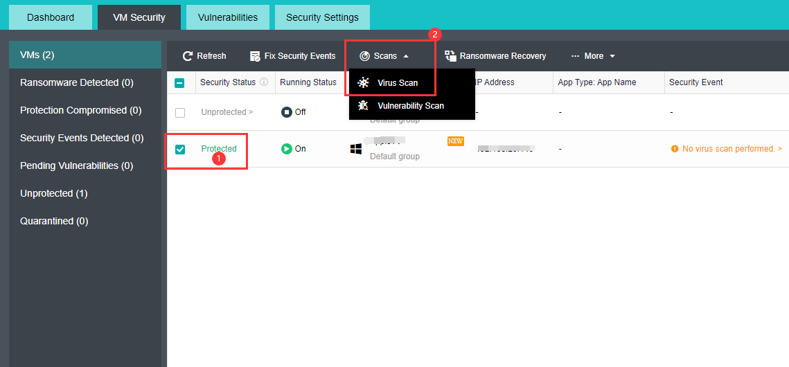
- Select the scan Method.
-
Quick Scan: Scans system key directories, key registry items, memory, and system running processes in a relatively short time.
-
Full Scan: Scans system memory, system running processes, key registry items, and files of all disk partitions in a relatively long time.
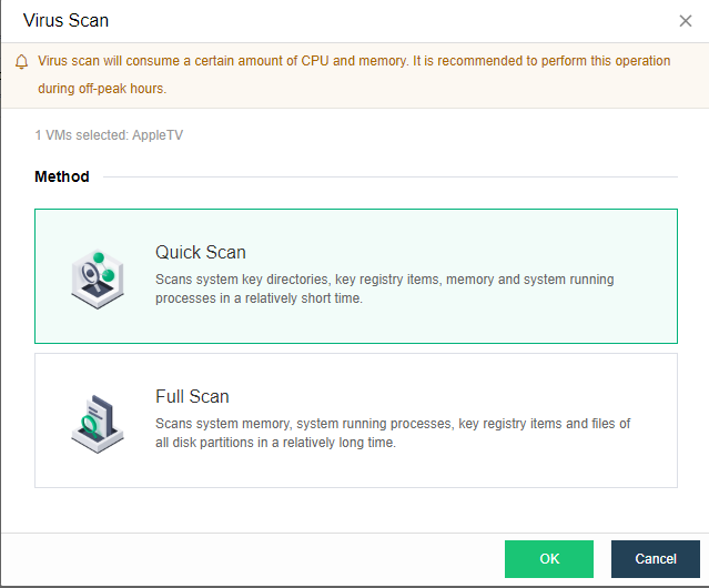
- After the scan is complete, click More > Virus Scan History to enter the scan result page.
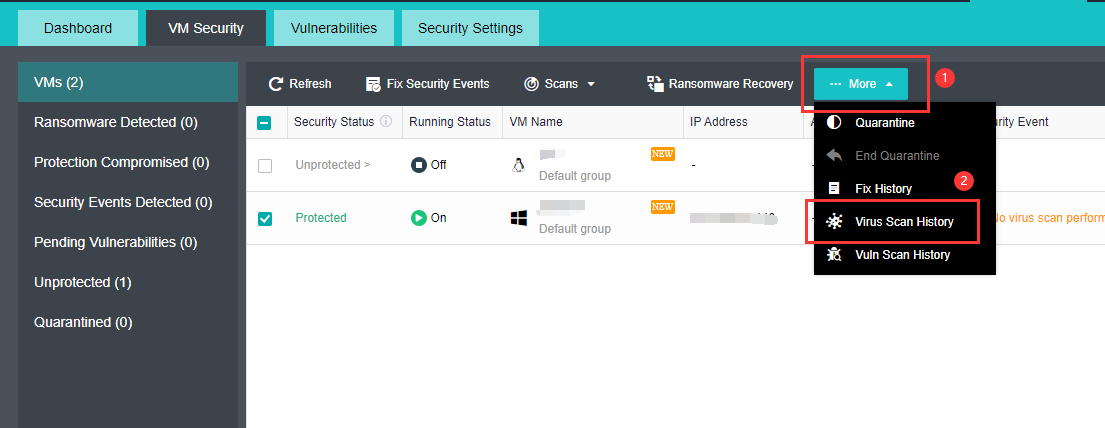
- Select the virtual machine in the virus scan history and click Details to manage viruses found in this scanning task. Operation include fix, trust, untrust and ignore.
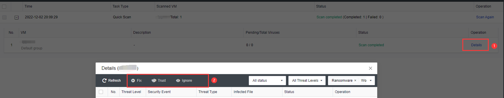
Vulnerability Scan
- Select virtual machines that need to perform vulnerability scans from the VM Security list and click on the Scans > Vulnerability Scan button.
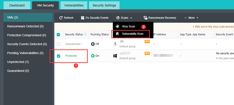
- Enter the Vulnerability Scan page. You can select or deselect the virtual machines that need to perform vulnerability scans.
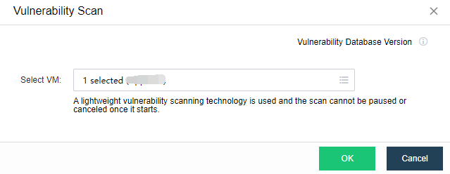
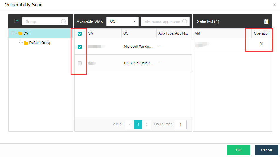
- After completing the scan, click More > Vuln Scan History to enter the result page.
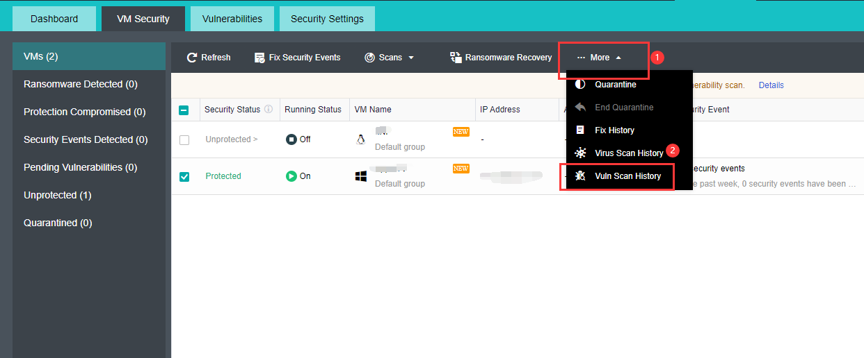
- In the vuln scan history, select the virtual machine and click Details to manage the vulnerabilities found in this scanning task, while Windows system vulnerability operations include: Patch or Ignore. Linux system vulnerability and application vulnerability status can be Marked as Fixed or Ignore.
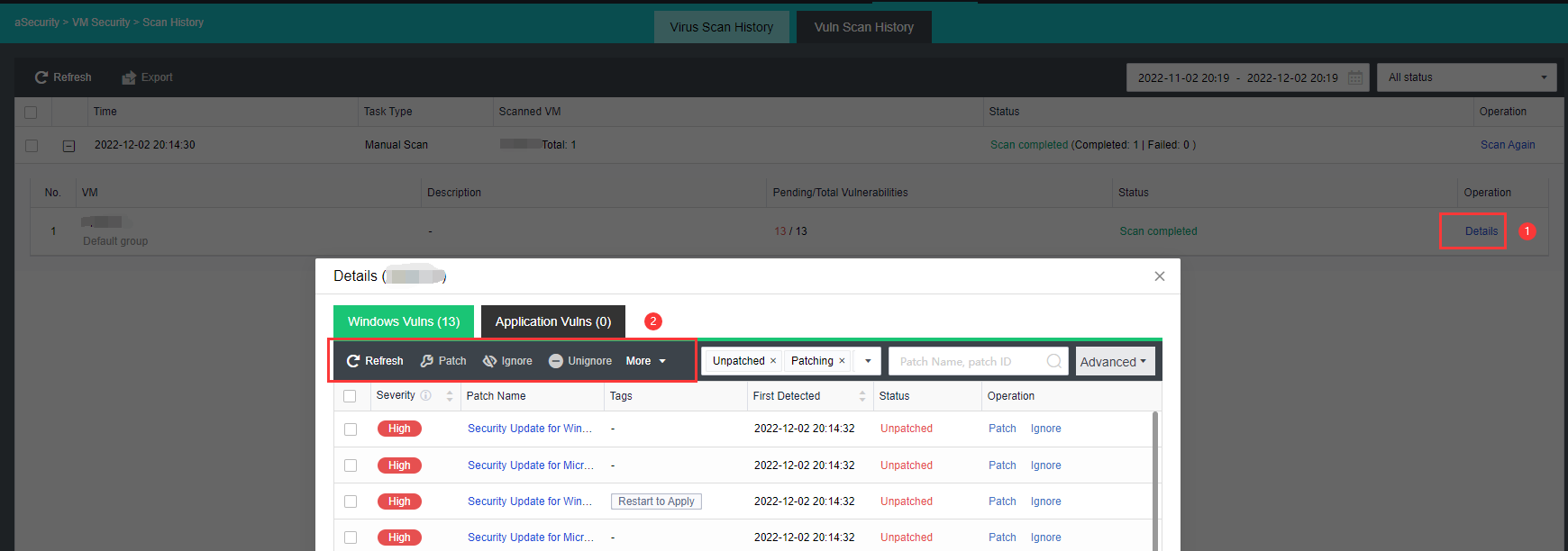
Quarantine
Description
When the system has been infected by computer viruses, to prevent the virus from spreading and infection, the aSecurity center provides the ability to quarantine. For virtual machines that have been encrypted, the quarantine can be done in seconds to ensure that the virus will not spread again.
Prerequisites
None
Precautions
-
Quarantine will completely disconnect the virtual machine network but will cause network disconnection and interruption of VM services for critical services. You can go to Distributed Firewall to configure rules to quarantine risks without service interruption.
-
The quarantined VMs will be added to the aSecurity quarantine policy. The policy will not take effect if the VM is directly connected to the edge.
Steps
- In the VM Security list, check the virtual machines at risk of virus spread and click More > Quarantine.
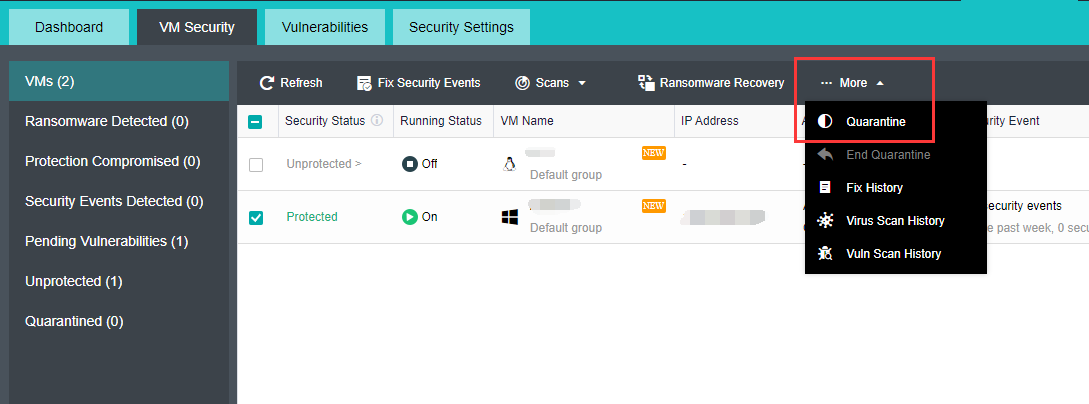
- After the virtual machine has been completely quarantined, the status of the virtual machine will be marked as Quarantined.
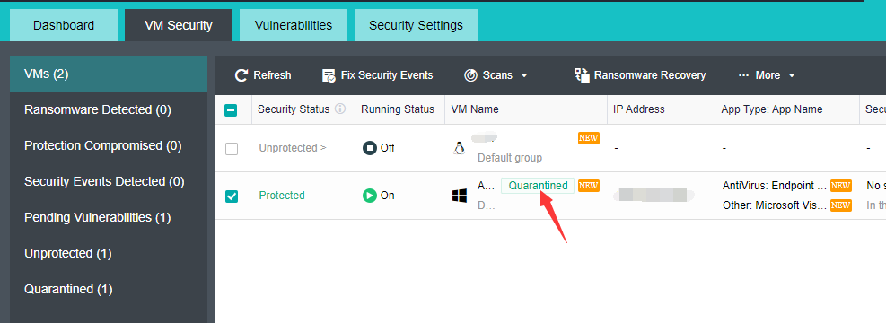
- When the quarantined virtual machine has been handled properly and can be released from quarantine, click More > End Quarantine to exit from quarantine.
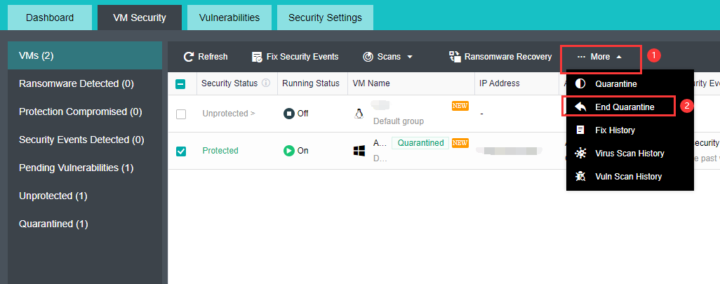
Ransomware Recovery
Description
- Sangfor aSecurity provides a guided ransomware recovery process, which can quickly and safely restore production or services without needing expert intervention.
- Sangfor aSecurity uses the linked clone method for service verification, which can be created in seconds. No additional storage space is required during the process. The environment is completely independent, and the virus will not spread during recovery.
- After the recovery point is determined and the recovery is performed, the entire process is strictly isolated from encrypted assets and other assets. The isolation will be released after the recovery is completed and the virus is confirmed to be safe.
Prerequisites
None.
Precautions
There is a time difference between the snapshot data from the ransomware recovery and the current data. Rolling back the snapshot will cause data loss. In a formal business scenario, please evaluate the impact of ransomware before deciding whether to roll back to the snapshot.
Steps
- In the VM Security list, select virtual machines under potential ransomware security events and click Ransomware Recovery.
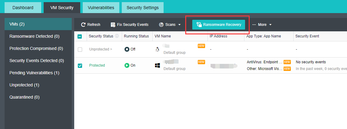
- Firstly, it is required to quarantine the virtual machine to prevent the further spread of ransomware to other virtual machines. Click the Quarantine button. After the quarantine is completed, click Next.
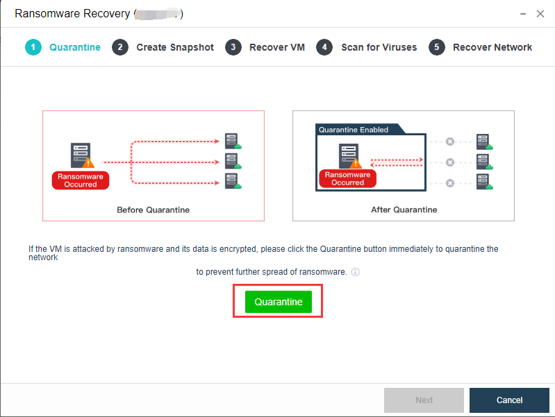
- Before proceeding to ransomware recovery, click the Create Snapshot button to create a snapshot for the virtual machine. After the recovery from ransomware is completed, you can use the snapshot to retrieve the encrypted data.
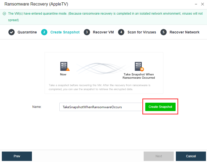
- After the snapshot is created, click Next to recover the virtual machine. This phase will show all the snapshots of the virtual machine. When the platform has detected the virtual machine’s security agent is abnormal or suspected ransomware virus, a snapshot will automatically create and name SuspectRansomewareSnapshotXXX. Click the Preview button, and the platform will create a new linked clone virtual machine. After the clone is completed, click the Console button to enter the virtual machine to check whether the virtual machine is being encrypted. If the virtual machine isn’t encrypted, click Start Recovery and input the admin password to begin the recovery.
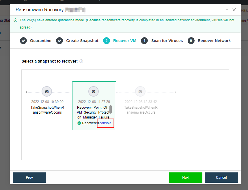
- After clicking the OK button, the platform will automatically delete all linked-clone virtual machines created in the previous preview and restores the selected virtual machine snapshot.
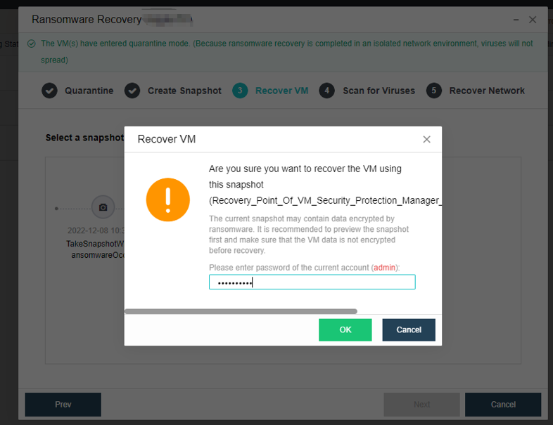
- After the recovery from the VM snapshot, click Next to enter the Scan for Viruses page. It is recommended to perform a full scan on the recovered virtual machine again. If a security event is detected, it can be dealt with immediately.
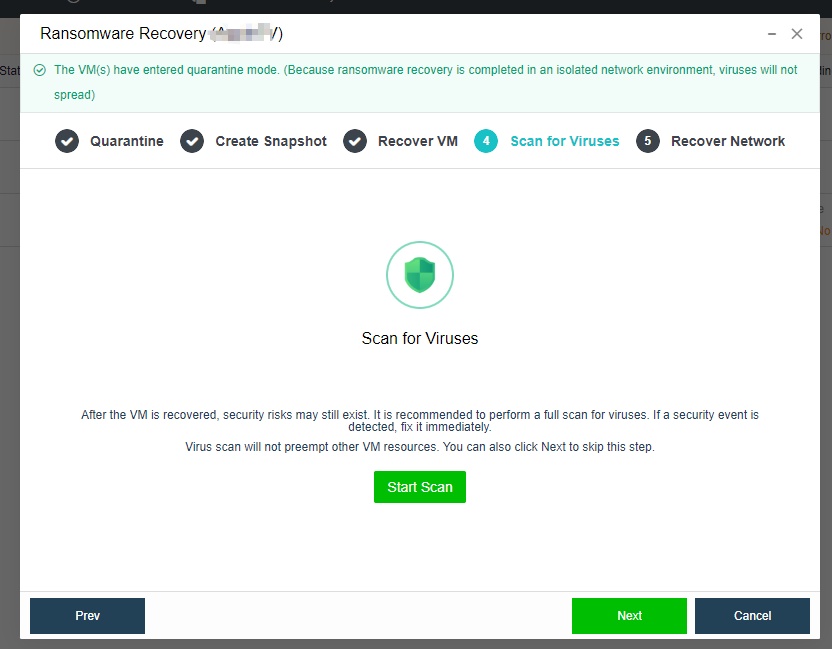
- For the scanned security events, you can click the Fix, Trust, or Ignore buttons above to handle the security events. After all security events have been addressed, click Next to enter Recover Network.
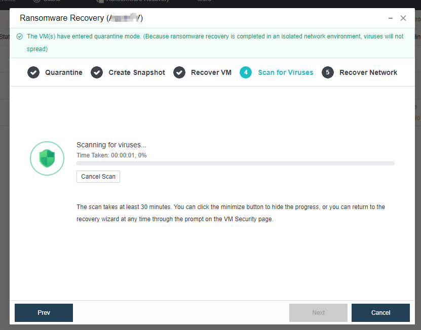
- Before recovering the network, since the current virtual machine data has been restored, to avoid secondary infection, it is recommended to check and confirm the security status of other connected virtual machines is appropriate and then click the Recover Network button. After the network is recovered, the virtual machine will be released from quarantine.
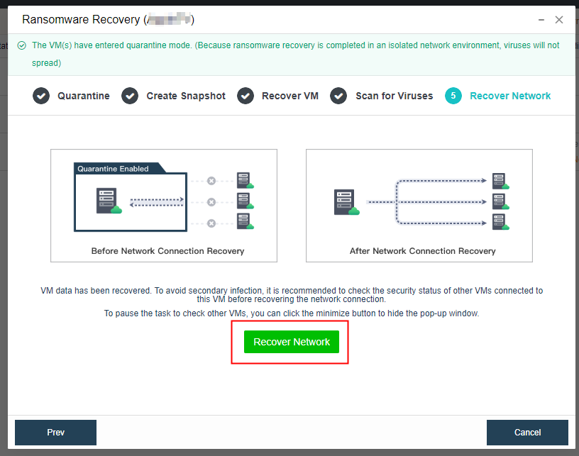
Fix Security Events
Description
- Sangfor aSecurity provides a full-stack guided security event fixing from network quarantine, snapshot recovery, and virus fix.
- The network quarantine adopts the SDN-capable micro-isolation solution, which does not need to modify any network configuration in the guest OS, has no impact on other services, and is completed in seconds.
- The fixing process guarantees the minimum RPO and RTO for anomaly occurrence. Sangfor aSecurity provides quarantine of files before fixing, encapsulating the files in an independent sandbox. At the same time, before fixing, a snapshot will be automatically generated. Even if accidental deletion occurs, the business can be restored quickly by restoring the snapshot. If the system crashes and cannot be powered on, the snapshot can also be used for rapid recovery.
Prerequisites
None.
Precautions
None.
Steps
- In the VM Security list, check the virtual machine that needs to undergo security events fix, then click the Fix Security Events.
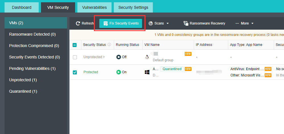
- Enter the Fix webpage.
-
Event Type is divided into: Virus Infection and Brute-Force Attack.
-
Threat Type: All are selected by default, and one or more types of threat can be selected individually.
-
Events to Be Fixed: All are selected by default, and one or more events can be selected individually.
-
Create Snapshot Automatically: It is disabled by default, you can enable it before the security events fix. After enabling, the snapshot will be automatically created for the virtual machine.
Note:
Taking snapshots of multiple VMs simultaneously will affect business performance. Therefore, it is recommended not to select too many VMs during peak hours or perform during non-business hours.
- Select VM: After enabling take snapshot, you can select VM that needs to take the snapshot. It can support up to 10 virtual machines at most.
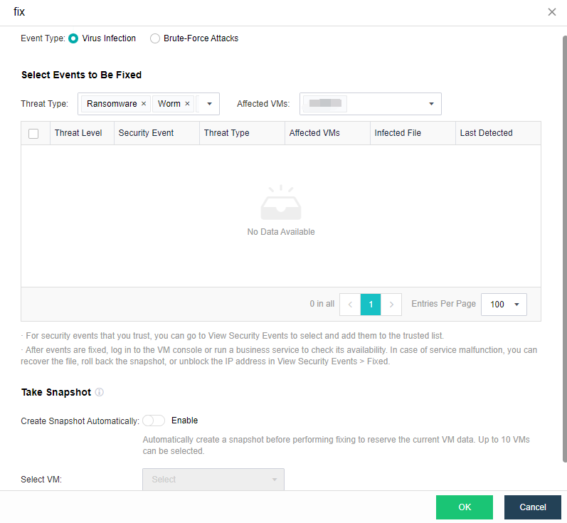
-
After the above information has been selected and confirmed, click the OK button to execute the security event fix.
-
After fixing, the virtual machine’s security event will be recovered.
-
Click More > Fix History to enter the Security Event Fixed list to view the above-fixed security event. If the business is still abnormal, you can click the Restore button for recovery.
-
Restore File: The file quarantined while fixing will be restored to its original location, which will overwrite any existing file with the same name. The security of the restored file cannot be guaranteed.
-
Recover VM From Snapshot: The VM will be recovered to the status at the selected snapshot time point. Please make sure that the VM data has been snapshotted or backed up. VM will be shut down before recovery and will cause business interruption. Therefore, it is recommended to perform during non-peak hours.
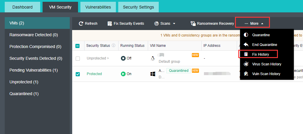
Security Events/Vulnerabilities Check
Description
- Sangfor aSecurity can fix, trust, or ignore the virtual machine’s security event.
- Sangfor aSecurity supports mark as fixed, patch, and ignore virtual machine’s vulnerabilities.
Prerequisites
None.
Precautions
It only supports patching Windows vulnerabilities and does not support automatic repairing of Linux system vulnerabilities and application vulnerabilities.
Steps
- Security Events
- Click on the Security Status of a selected virtual machine and click on View Details to enter the Security Event page, select security events that need to be fixed, then click Fix to fix the security event.

- If the business is abnormal after the security event is fixed, you can go to the Fixed list and click the Restore button to recover the quarantined files.
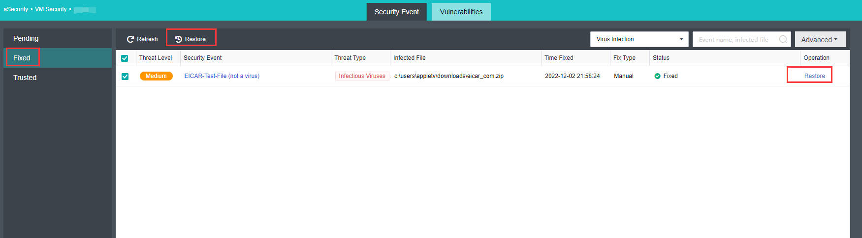
- When it needs to add trust to a security event file, click the Trust button.
Note:
- After the trust is executed, files with the same MD5 value on other virtual machines will be trusted at the same time.
- The platform will no longer prompt risk and fix reminders for trusted security events.

- To untrust, go to the Trusted list and click the Untrust button to untrust the file from the security event.
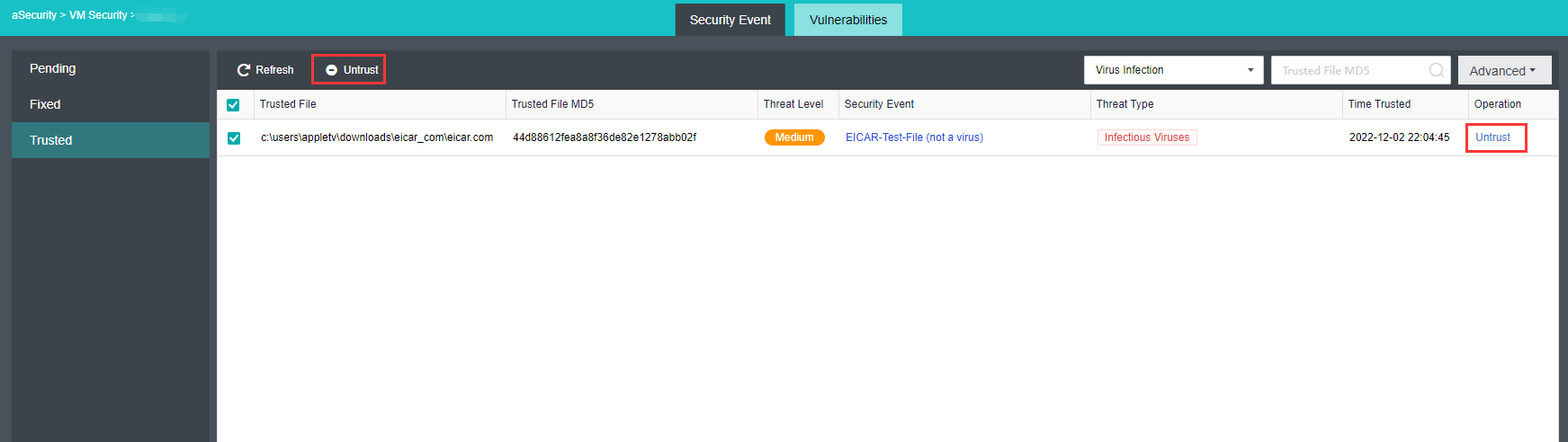
- If a security event does not need to be processed, you can click the Ignore button.
Note:
After ignoring it, the platform will still prompt an alert when it detects the same event again.
- Vulnerabilities
- Click on the selected virtual machine’s Pending Vulns, then select Windows Vulns or Application Vulns to select vulnerabilities that need to be patched and click the corresponding button to Patch or Ignore.
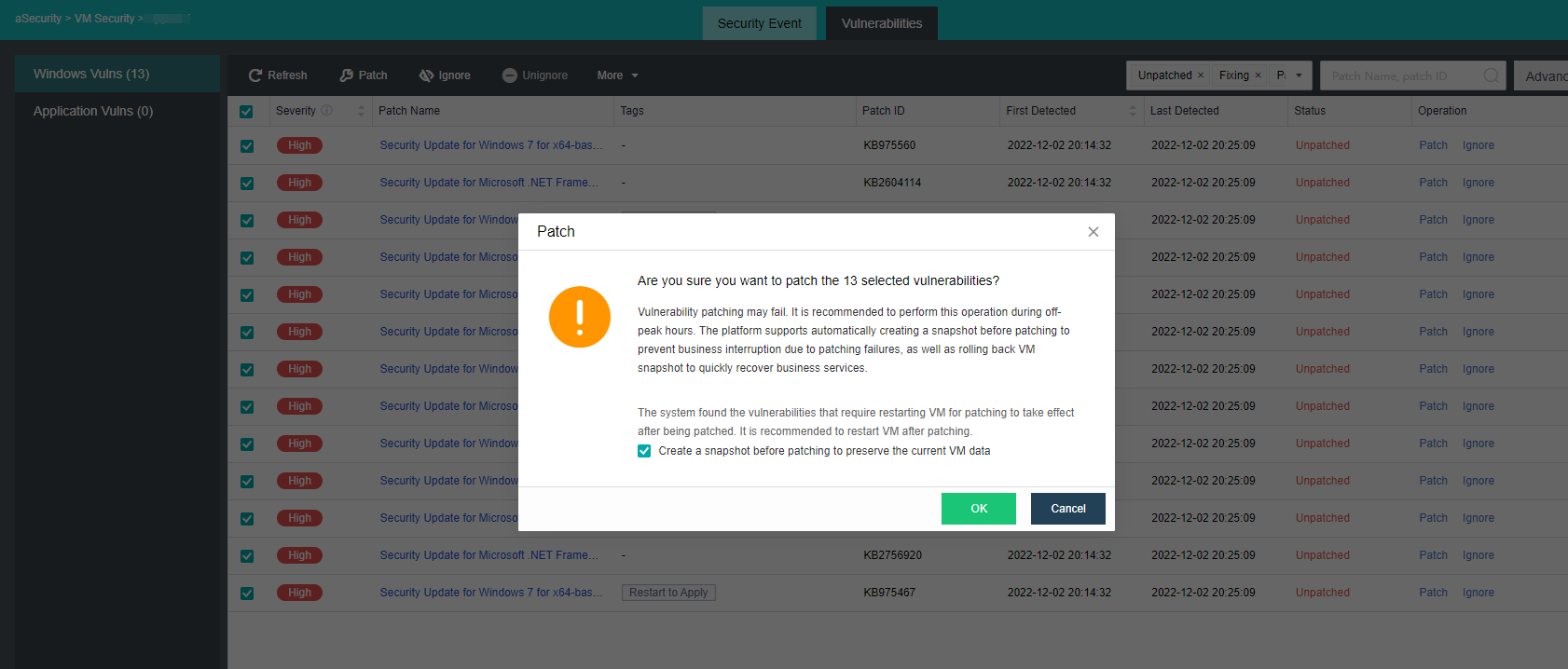
- Go to the Linux Vulns or Application Vulns page. The corresponding vulnerability can Mark as Fixed or Ignore.
- Mark as Fixed: when the user has manually fixed the vulnerability, it can be Mark as Fixed. Vulnerabilities that mark as fixed, if the vulnerability is still detected upon the next scanning, a security event will still be generated.
- Ignore: If a vulnerability does not need to be fixed currently, you can click the Ignore button to ignore it. The vulnerability will no longer prompt for the currently affected VM after clicking Ignore, but the vulnerability record will still be visible.
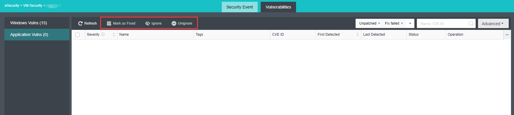
Vulnerabilities
Description
Sangfor aSecurity provides a holistic view of the vulnerabilities for virtual machines, which can comprehensively monitor the risk of business system vulnerabilities, and provides one-click Windows vulnerability fix capabilities in batch to improve business security protection.
Prerequisites
None.
Precautions
Only supports patching for Windows vulnerabilities. Support one-click scan for Linux vulnerability and application vulnerability but do not support automatic fix for Linux system.
Steps
- Go to the Vulnerabilities page, and the platform supports automatic discovery and reporting of Windows vulnerabilities, Linux system vulnerabilities, application vulnerabilities, and manual vulnerability scanning.
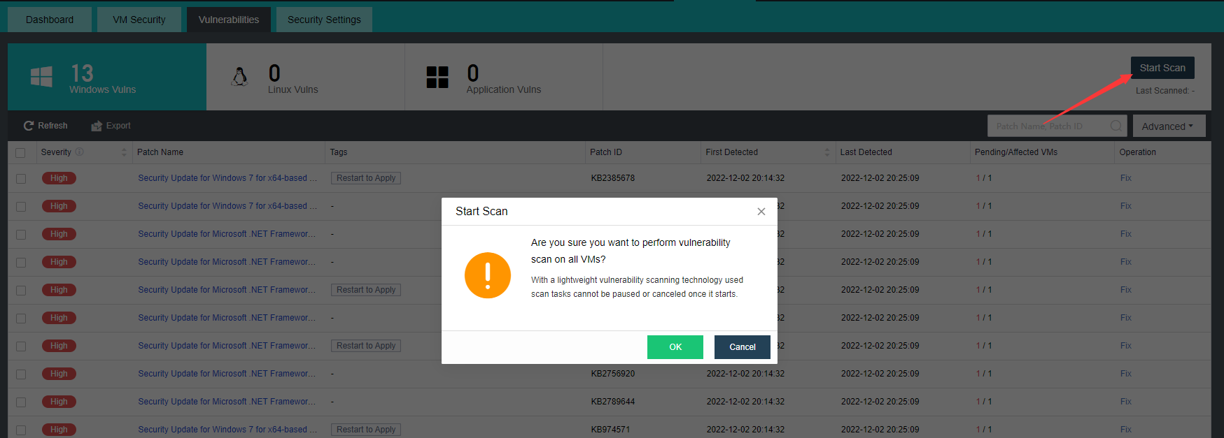
- The vulnerabilities page includes vulnerability information such as Severity, Patch Name, Tags, Patch ID, First and Last Detected, Pending/Affected VMs. Click the Fix button on the operation bar to view the detailed information on the vulnerability and the list of affected virtual machines.
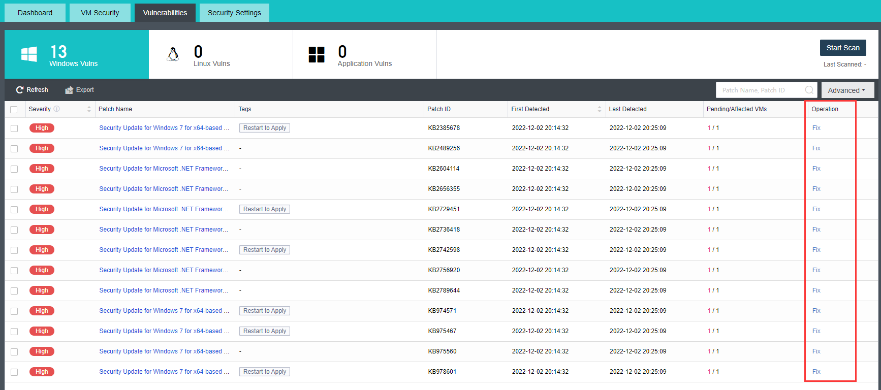
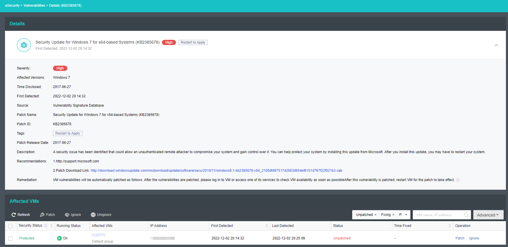
- Check the virtual machines that need to be fixed and click the Patch button to execute a single or batch vulnerability patch. It is recommended to check the Create a snapshot before patching to preserve the current VM data. After checking, the platform will automatically take a snapshot of the virtual machine before the vulnerability is fixed so that the business can be quickly restored in the event of a fixed failure.
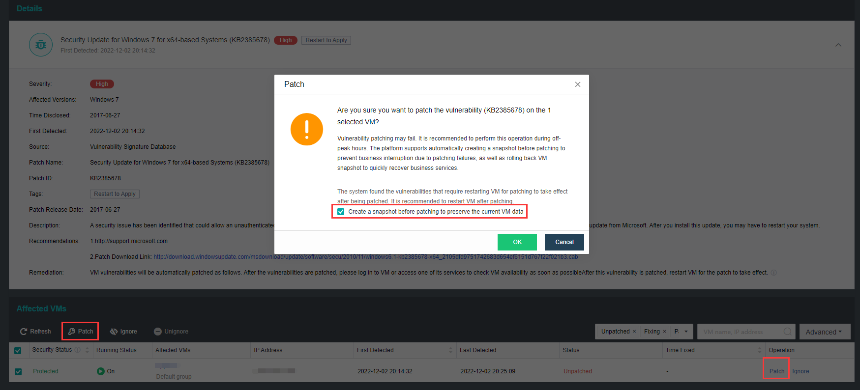
- The platform also supports selecting single or batch virtual machines and exporting the vulnerability scan results. The exported content includes vulnerability Severity, Vuln/Patch Name, Tag, Patch/CVE ID, VM Name, IP Address, Status, Remarks, etc.
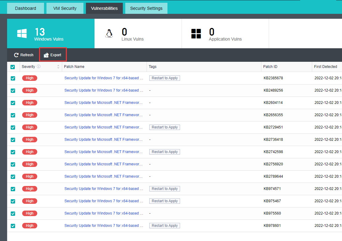
Security Settings
Data Protection Policy
Description
The Sangfor aSecurity supports enabling data protection policies. All virtual machines are protected by the policy, and a snapshot will be automatically created for each VM in the policy daily. When it detects that the security agent is uninstalled and there is a suspected risk of ransomware, the snapshot is immediately generated for data protection; when an abnormality is detected, persist the original timed protection files to avoid being overwritten by the virus.
Prerequisites
The snapshot policy in the Sangfor HCI platform has been set to automated mode, and the data protection policy cannot be enabled in manual mode. Mode settings can refer to Chapter 5.2.13 Snapshot Policy.
Precautions
- The data protection policy will automatically create a snapshot for each VM in the policy daily. It is recommended to prioritize adding important virtual machines into the policy to rapidly recover business services from rolling VM snapshots during critical security events such as ransomware.
- Data protection policy usually only retains the latest snapshot file. When critical security events such as malicious damage and suspected ransomware are detected, the latest snapshot file before the event will be kept for 7 days.
- In the data protection policy, there are limits on the number of snapshots taken every day:
- Hybrid volume: vm_num=(0.6(host_num-3)4+12)(1 SSD capacity0.5*SSD disk number/480G).
Note:
If the storage capacity is heterogeneous (not equal), take the smallest storage capacity as a reference.
- All-flash Datastore: 2048
-
If the selected virtual machine or consistency group already has a snapshot policy, it will be removed from the original policy and added to the current data protection policy.
-
The virtual machine/consistency group added to the data protection policy will take a snapshot once a day.
Steps
- In aSecurity select Security Settings > click on Data Protection Policy to enter the page, and click the Enable button (it is disabled by default) to enable data protection policy.
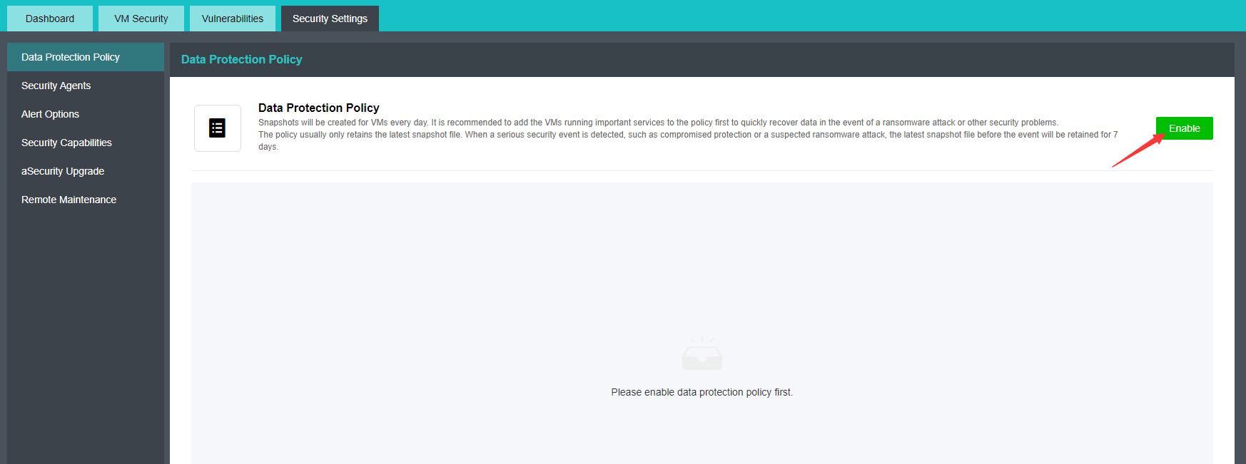
- After enabling, two snapshot policies of aSecurity will be automatically generated by the system in Reliability > Snapshot > Snapshot Policy.
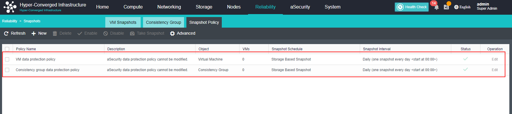
- Select Virtual Machine or Consistency Group and click Add Virtual Machine or Add Consistency Group to add the virtual machine/consistency group to the data protection policy.
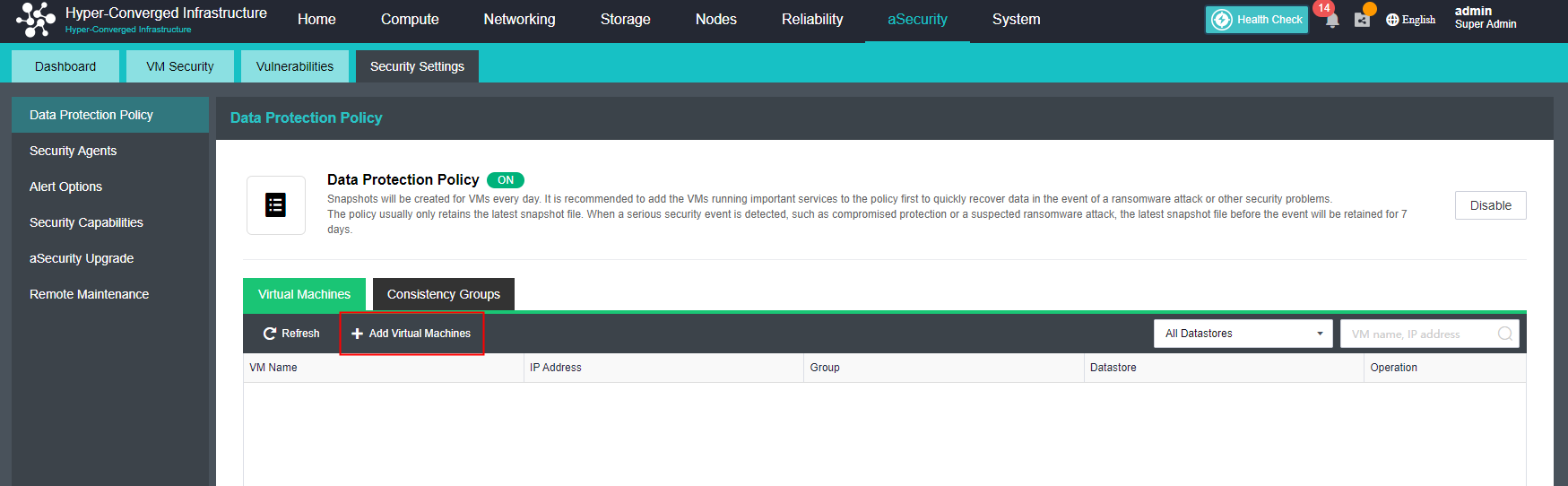
Alert Options
Description
Sangfor aSecurity supports real-time detection of security events that threaten the virtual machine, such as brute force attacks, webshell backdoors, ransomware, Trojan virus, etc. After the virus is detected, an alert email will be sent to inform the user that the Sangfor HCI platform has detected a security event.
Prerequisites
SMTP server is configured.
Precautions
The aSecurity currently doesn’t support SMS notifications.
Steps
- In Security Settings > Alert Options, click Edit to go to the Email Notification configuration page, click the New button and check the aSecurity Alert. Platform alert configuration can refer to the Chapter 10.5 Alert Options.
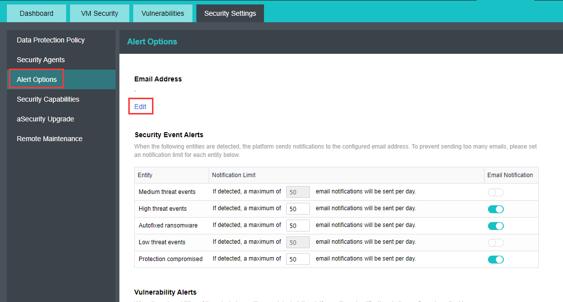
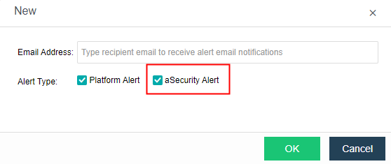
- When the platform detects a security or vulnerability event, it will send an alert to the recipient email according to the configured security event alerts.
- Security Event Alerts: The platform supports configuring a maximum number of email notifications to be sent daily for security event alerts ranging from 1 to 1000.
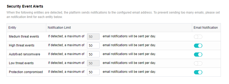
- Vulnerability Alerts: The platform supports configuring the vulnerability alert of vulnerability severity and notification frequency to send an alert email. When the notification frequency is selected as Realtime, the maximum number of email notifications to be sent per day ranges from 1 to 1000.
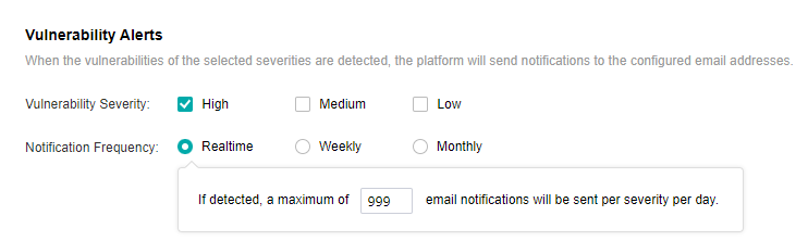
- Click Save to complete the aSecurity alert options configuration.
Security Capabilities
Description
Sangfor aSecurity provides the platform with an automated detection, monitoring, and response system to manage and control security events from one platform.
Prerequisites
The installation and deployment of the virtual machine security protection management(ES/EDR) platform have been completed. For details, please refer to Chapter 3.15.2 VM Security Protection Deployment.
Precautions
None
Steps
- In Security Settings > click on the Security Capabilities, then click View Default Security Settings, which can view the security settings for Windows/Linux virtual machine security protection.
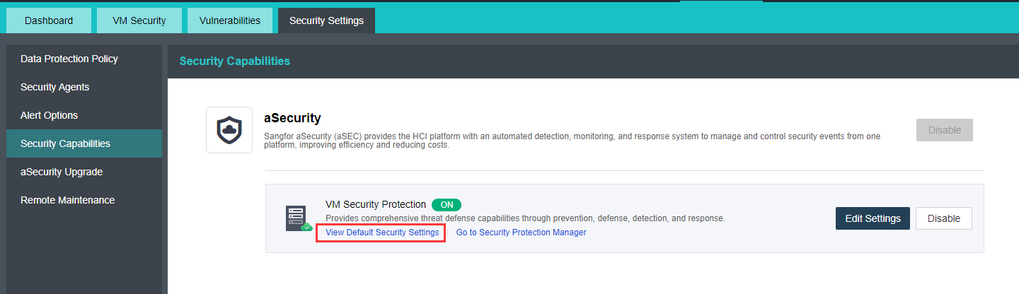
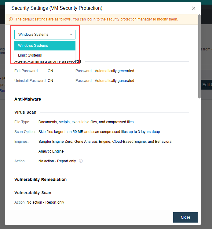
- Click Go To Security Protection Manager to log in to the virtual machine security protection management platform(ES/EDR) for other personalized configurations.
aSecurity Upgrade
Description
This chapter guides the administrator to upgrade Sangfor aSecurity.
Prerequisites
The new version upgrade package is ready.
Precautions
None.
Steps
- Go to aSecurity > click Security Settings > then select aSecurity Upgrade, click the Upgrade button and follow the instruction to perform aSecurity firmware upgrade.
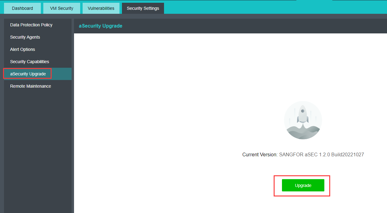
Remote Maintenance
Description
Remote maintenance is used for technical support to provide remote diagnostics, troubleshooting, and other solutions to improve the system’s performance or to recover business service.
Prerequisites
None.
Precautions
After being enabled, the SSH port will be automatically disabled 4 hours later.
Steps
- Go to aSecurity > click Security Settings > then select Remote Maintenance, and click the Enable button to enable the remote connection for technical remote maintenance.
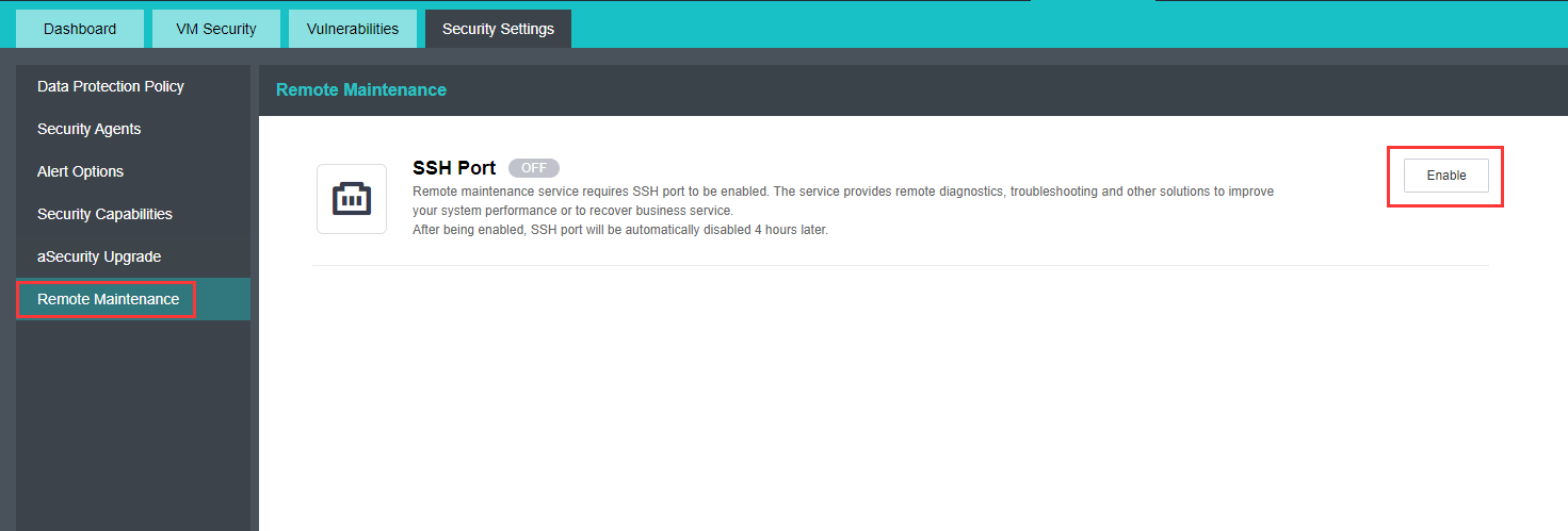
HCI Platform Configuration Guide
Viewing Node/Cluster Running Status
Description
You need to check the status of the cluster nodes to view the platform’s usage.
Precautions
None.
Prerequisites
None.
Steps
On the Home page, you can see the running status of the nodes in the cluster, including the number of nodes in the cluster, the number of virtual machines, and the number of storage, as well as the usage of CPU, memory, and storage in the cluster, as well as the usage of each node.
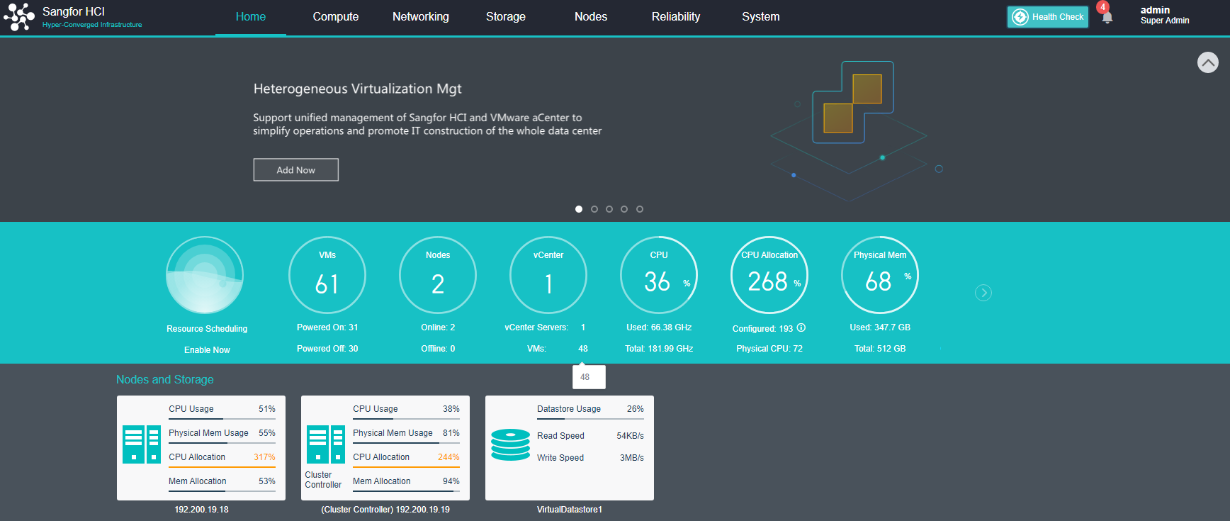
Port Management
Description
Supports manually disabling or enabling HCI interfaces. It supports enabling and disabling the SSH interface and can set the IP whitelist for accessing the SSH interface.
Precautions
- Disabling the port on the port management interface only closes the external port of the cluster, and does not affect the functions in the cluster. For example, shutting down the VM migration service only affects cross-cluster migration, not migration within the cluster.
- After the remote SSH login to the HCI platform, if the operation exceeds 10 minutes, the session will be automatically disconnected by timeout.
- A single IP can only access a single HCI cluster 100 times within 10 minutes.
Prerequisites
- Log in to the console, enter the System > Port Management interface, and Enable or Disable the ports.
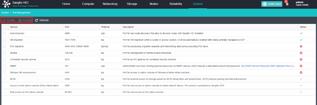
- Enable or Disable the SSH port. After the port is Enabled, IP login can be restricted. Check the Allow SSH access by IP address checkbox and enter the allowed IPs in the input box. The maximum number is 100 and click Save.
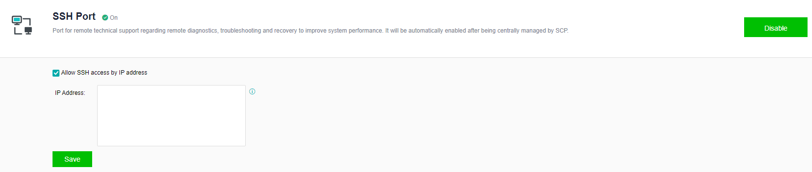
Certificate Setting
Description
The SSL certificate establishes an SSL secure channel between the client and the HCI device. When the client browser marks a danger warning on the HTTPS website, installing the SSL certificate can make the client trusted by the browser and remove the insecure warning. Sangfor HCI platform supports manual import of SSL certificates.
Precautions
- The certificate file currently only supports the .crt format. If there are certificates in other formats, they need to be converted.
- The upper limit of the key file size is limited to 1MB.
Prerequisites
A valid certificate file in .crt format has been obtained.
Steps
- Log in to the console, enter the System > Certificate Settings interface, import the correct .crt and .key certificates, and click Save.
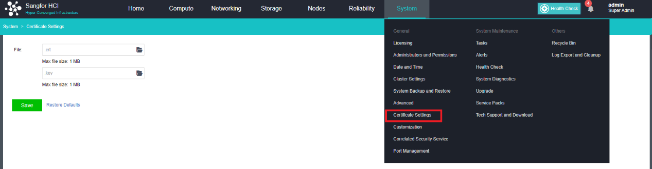
- It can be seen that after importing the trusted certificate, the client is trusted by the browser, and the insecurity warning is removed.
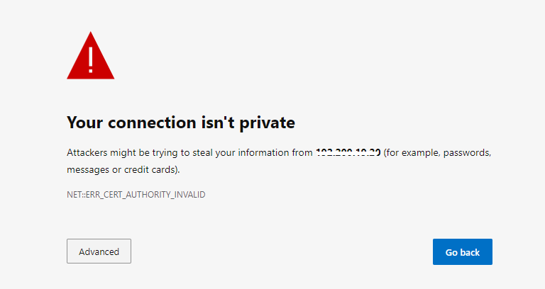
Viewing the Alarm Log
Description
Check the alert log to locate the problem.
Precautions
None.
Prerequisites
None.
Steps
- You can view HCI platform alarm information through System > Alerts.
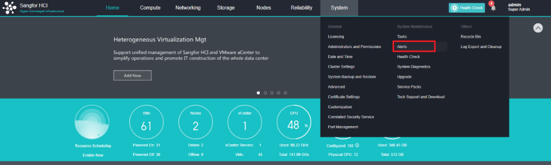
- The required alert information can be filtered through the filter function.
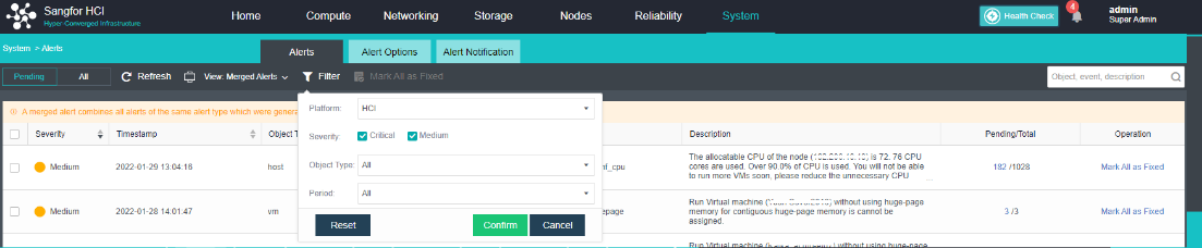
Alert Options
Description
- Set the thresholds of platform alert items, including Host, Storage, Virtual Machine, Virtual Network Device, Cluster, and various monitoring items.
- Send the set alert content to the specified email address/mobile phone number by email/SMS.
Precautions
-
SMS notification: After the cluster controller is offline for some time and back online, the user may receive multiple SMS messages (up to 50) simultaneously. Network exceptions may occur when the node is offline, which may cause the same alert SMS to be sent twice (alert retry mechanism).
-
Some text messages have a lot of content and may be split into multiple pieces by the operator for sending.
Prerequisites
Email notification: The mail server is configured.
Steps
-
Configure the alert settings.
-
Navigate to System > Alerts > Alert Options. Select the alert threshold to be adjusted and save the changes. Host alert events settings.
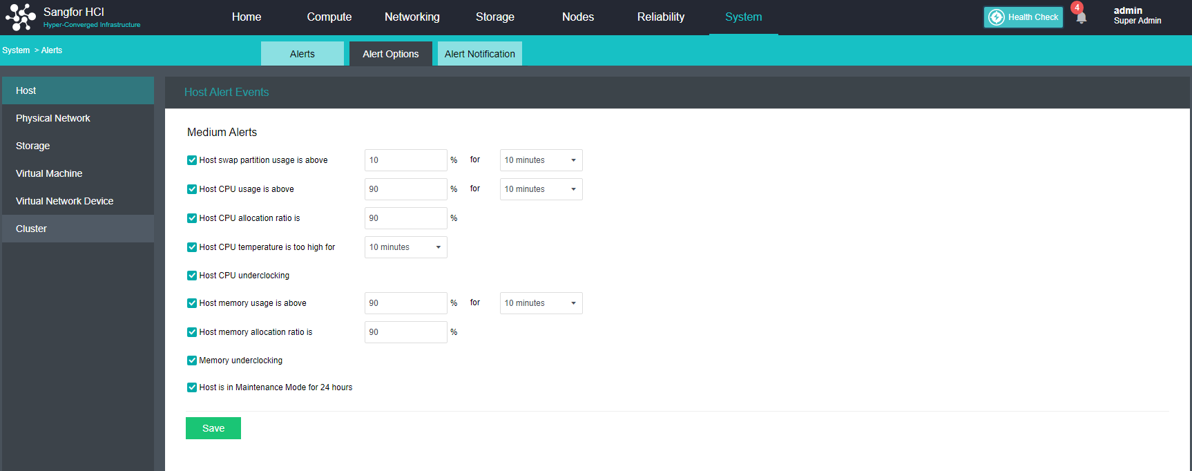
-
Physical network host network alert events settings. Set the conditions, including the Node is offline, NIC compatibility, NIC is damaged, NIC optical transceiver abnormal, error packet, and other alarm items.
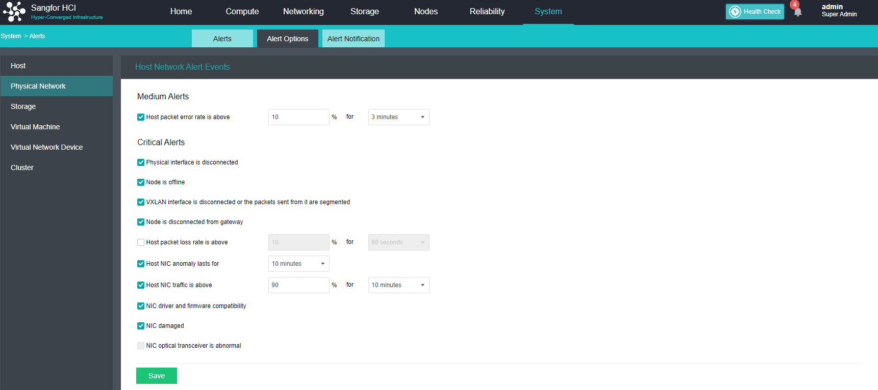
- Storage alert events settings.
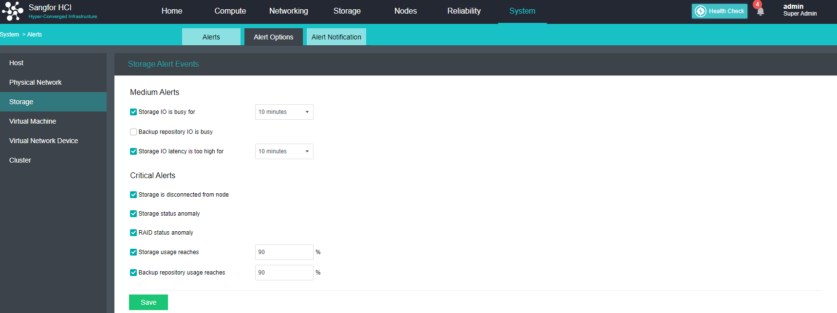
- Virtual Machines alert events settings.
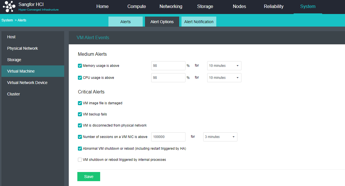
- Virtual network device alert events settings.
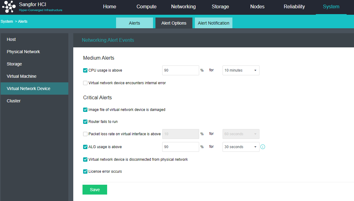
- Cluster Alert Events settings.
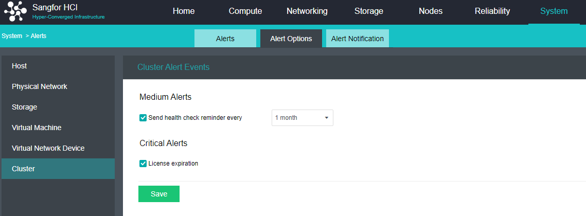
Syslog Configurations
Description
Automatically upload operational logs and kernel logs to the log server.
Precautions
None.
Prerequisites
There is a log server that can communicate with the management port.
Steps
Navigate to System > Log Export and Cleanup > Syslog Server. Check the Enable Syslog checkbox, and configure the IP, port, and protocol of the Syslog server. After configuration, click Test Connectivity to confirm that the Syslog server can be connected. Click Save and the selected logs will be automatically uploaded to the Syslog log server.
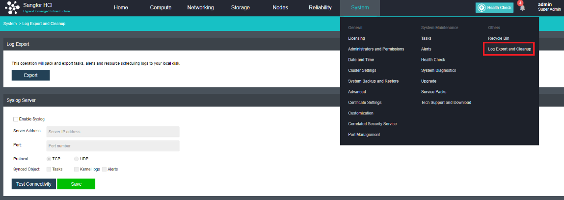
Administrators and Permission
Permissions
Description
The permission here is equivalent to a role function, which is what kind of permission a resource has.
Precautions
None.
Prerequisites
None.
Steps
Add permission
- Navigate to System > Administrator and Permissions > Permission.
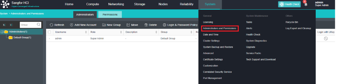
- Click New and then Add New Permission window will pop up.
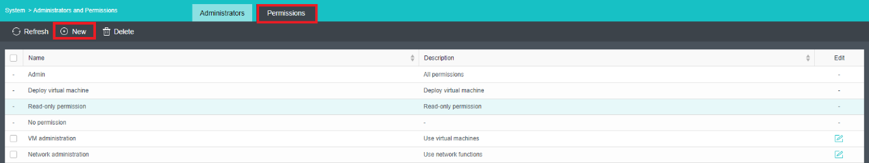
- Enter the permission name and description (the name is required, the description is optional, and the name needs to be unique), then select the specific permission required and click OK.
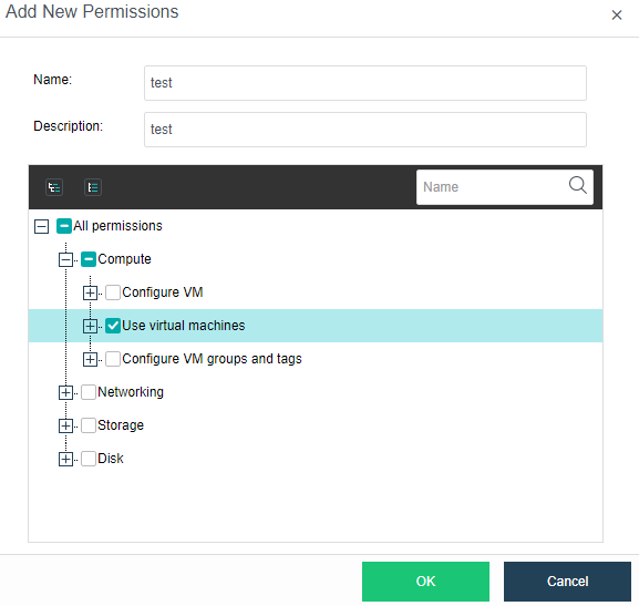
Edit Permission
After adding permission, you can modify the name and description of the permission as well as the specific permission content included in the permission as needed. Click the edit icon to the right of the permission you want to edit to edit it.
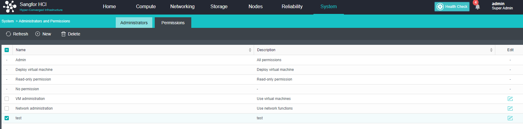
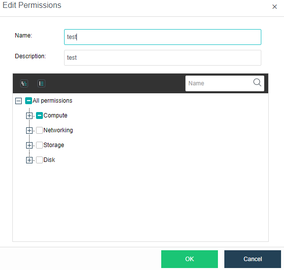
Remove Permission
Select the permissions and click Delete. Multiple permissions can be removed at the same time.
Notice:
Deletion fails when permissions are granted to a user.
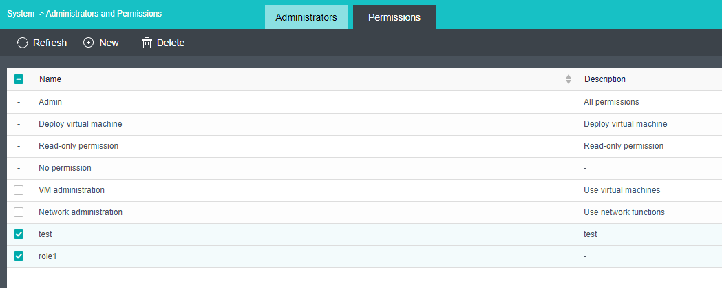
Adding New Users
Description
You need to create a new user on HCI and give different permissions.
Precautions
- After the username is confirmed, it cannot be modified. The description is optional and can be modified.
- The resource quota only limits the virtual machines created by the user. The virtual machines created by other users are authorized to be used by the user without occupying the resource quota of the user.
- Users and permissions can only be configured by the admin user.
- The system administrator has no right to configure the permissions for the following functions: VMware-related functions, consistency group snapshots and snapshot policies, correlated security service, and P2V migration.
Prerequisites
Permissions are already configured.
Steps
- Navigate to System > Administrators and Permissions > Administrators and click Add New Account, configure user name, description, role, group, password, and other information, and then click OK.
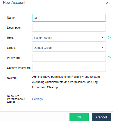
- On the Resource Permissions & Quota > Settings page, select the resources for which permissions need to be configured and grant pre-configured permissions. Resources include virtual machines, virtual networks, storage, and physical disks.
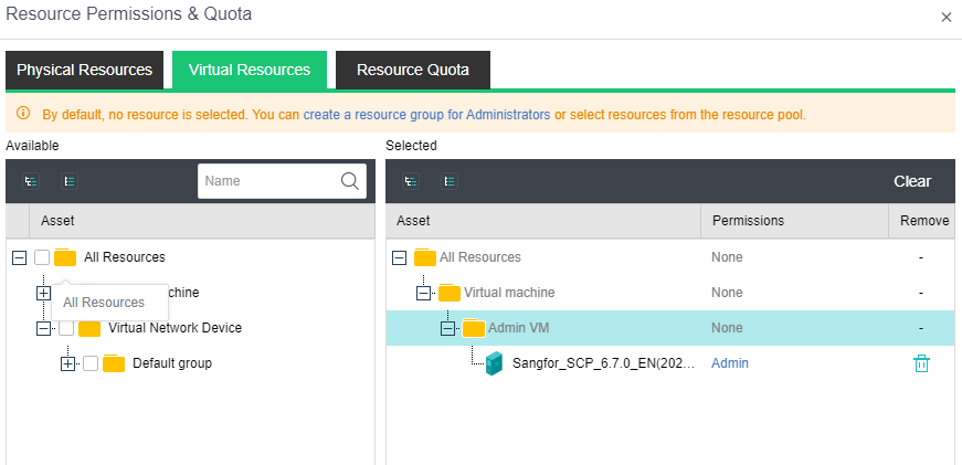
Roles of Three Members
Description
Create three administrator roles: System Admin, Security Admin, and Audit Admin, and assign different permissions to manage the cluster.
Precautions
- The security administrator has the viewing rights of platform users, including viewing user lists, viewing user quotas, and modifying user passwords. The None method can add users and modify user quotas.
- The audit administrator has the configuration rights for operation logs, alarm logs, and log management. The operation logs include all the operation logs of the platform, scheduling logs, and HA logs.
Prerequisites
None.
Steps
-
For the steps of creating a new system administrator, please refer to Chapter 10.7.2 Adding New User.
-
Log in to the console as admin, navigate to System > Administrators and Permissions, click Add New Account configure name, description, group, password, and other information. Select Security Admin for the role, and then click OK.
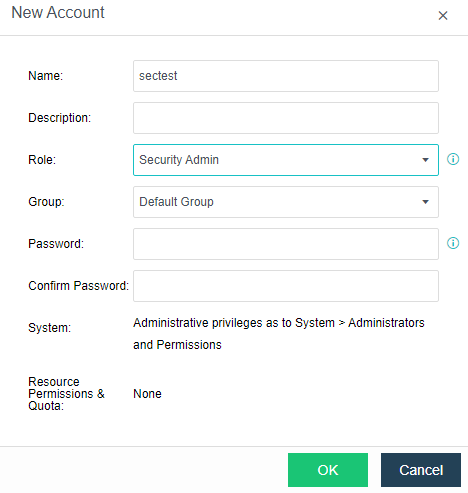
- Click Add New Account to configure the name, description, group, password, and other information, select Audit Admin for the role, and then click OK.
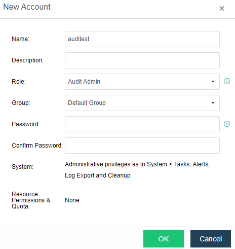
Password Policy
Description
All users on the platform can be forced to issue password policies, including password length, complexity, validity period, and the number of incorrect entries.
Precautions
- Password policies must be followed when creating new users.
- If an existing user does not comply with the password policy, it will be forced to modify it during login.
Prerequisites
None.
Steps
Use admin to log in to the console, navigate to System > Administrator and Permissions > Administrator, click Login & Password Policy, configure the minimum length for the password, password complexity, password validity, and max password retry attempts, and click OK.
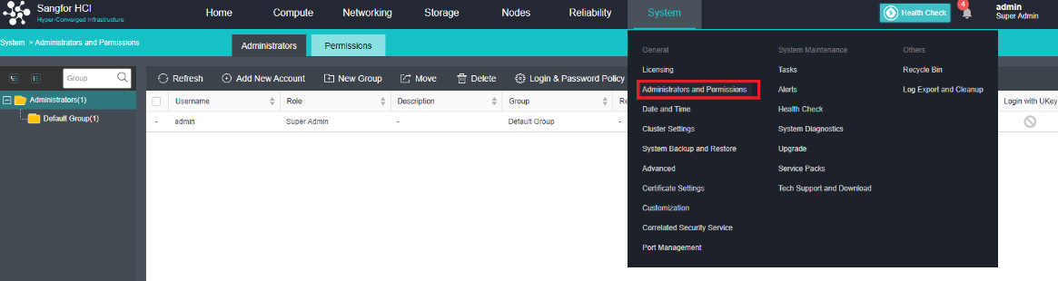
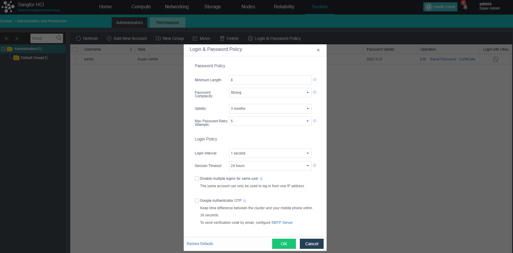
Login Restriction
Description
It can control user login based on the following scenarios.
- Login control policy based on IP address and MAC address.
- Terminal device-based login control policy.
- Time period-based login control strategy.
Precautions
- If you set a restricted login terminal, you must log in to the terminal that meets the conditions.
- The UUID limitation of terminal devices only supports Windows.
Prerequisites
User already exists.
Steps
- Go to System > Administrators and Permissions > Administrators, and click Login & Password Policy.
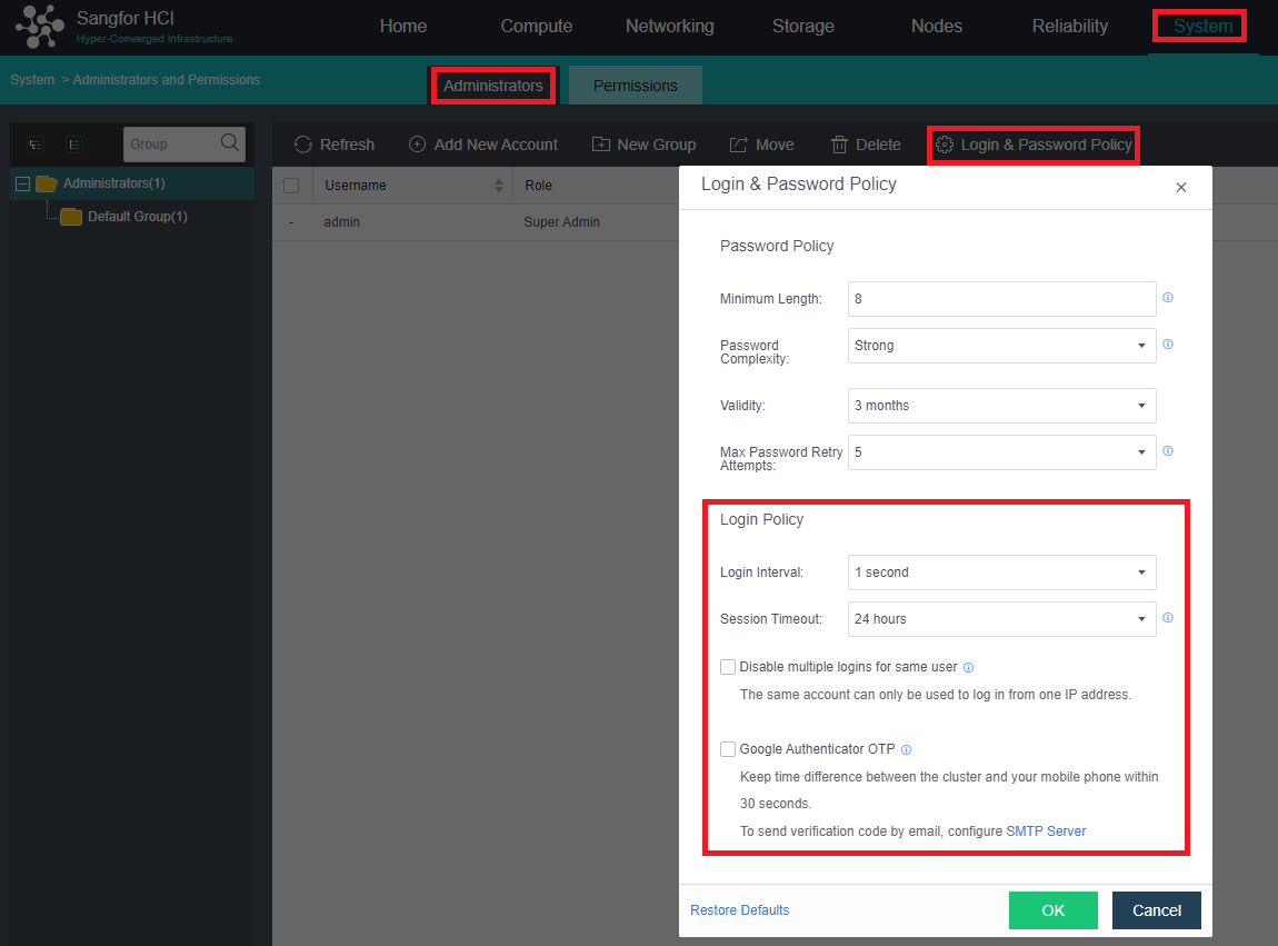
- Select the user to be restricted and edit the user.
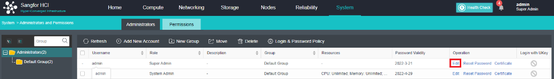
- Add constraints as required by the constraints.
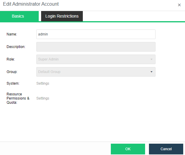
UKey Two-factor Login Configuration
Description
The HCI platform adopts a two-factor login authentication method based on USB-KEY and user account passwords. The administrator sets UKey policies for all platform users, including whether to bind UKey and enable UKey login authentication.
The purpose of Ukey authentication login is to restrict illegal users from logging in to the platform and ensure that they can log in normally only with the registered UKey.
The UKey authentication function module exists in the background as a service. The browser can obtain the UKey-related information of the terminal through the service’s interface and send commands to make the service burn the certificate to the UKey.
Precautions
- Only one UKey can be connected to each terminal at the same time.
- Repeated writing of UKey will overwrite the original information.
- After binding and enabling UKey, the terminal that the user logs in to must insert the corresponding UKey, and then enter the correct account password to log in to the platform.
- Only the system administrator can operate binding UKey, other administrators do not have this operation, and the Sangfor UKey service client needs to be downloaded and installed for the binding operation.
- After enabling the USB-KEY authentication login, you cannot log in to the cluster if the authentication key is lost or damaged. Please contact technical support for help.
Prerequisites
- The corresponding user has been created.
- UKey is ready.
- Windows Terminal.
Steps
- Plug the UKey into the operating terminal PC device, and bind the administrator to the UKey. At this time, the platform requests to obtain the current version number of the service. If the service does not respond, it will prompt you to install the service and provide a download link. After downloading, the user needs to install it manually. If the version number of the service response is not the latest, the user will be prompted to download the latest installation package. Otherwise, you cannot proceed to the next step. After installing the latest installation package according to the prompts, restart the browser, log in to the platform again, and proceed to steps 1 and 2. The following window should pop up normally. If you cannot use it, you can click the Installation Guide and configure the environment correctly according to the guide.
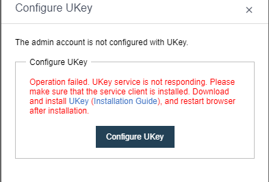
-
Click Bind UKey: At this point, the system will confirm the number of UKeys currently inserted into the terminal. Only one UKey can be programmed at a time. If there is no UKey or more than one, improper operation will prompt. The owner of the requested UKey. If the currently inserted UKey already has other user information, a prompt to confirm overwriting will pop up. After the UKey is burned, the platform will generate a public-private key pair, the private key is stored in UKey, and the public key is stored in the background. After the user and KEY binding are completed, a completion prompt will pop up.
-
After the binding is completed, you can enable certificate management for the user and enable or disable certificate login in the user list management as needed.
Google OTP Two-factor Login Configuration
Description
HCI 5.8.8R1 version starts to support the two-factor login authentication method based on Google OTP and user account password. Google Authenticator OTP can be configured in the platform user login settings.
Precautions
- This version only supports HCI to enable OTP, whereby SCP does not support it.
- Only the admin administrator has permission to enable Google Authenticator OTP.
Prerequisites
Prepare Google OTP server and client.
Steps
- Navigate to System > Administrator and Permission > Login & Password Policy.
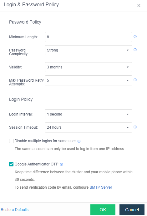
- Before enabling it, you need to configure the SMTP server if you need to send a verification code to the mailbox (use the mailbox to receive the login verification code).
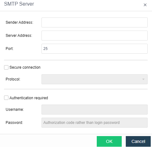
-
After the Google Authenticator OTP is enabled, it will automatically log out of the current login status and log in again. Register OTP by installing the authenticator app (Google Authenticator APP) on your mobile device. After the installation is successful, scan the QR code.
-
After entering the verification code, enter the configuration receiving mailbox page and configure the specified mailbox. You can obtain the verification code through this mailbox to log in to the platform when the device is not around.
Modifying the Cluster IP Address
Description
There are two cases for modifying the cluster IP address:
- Only modify the cluster IP address.
- Modify the IP address of the node management communication interface and the cluster IP address in the cluster.
Precautions
- After modifying the node’s IP address in the cluster, you need to use the new IP to log in. You may need to change the switch’s configuration and modify the corresponding VLAN.
- When only the cluster IP address is modified, ensure that the modified IP is in the same network segment as the original cluster IP.
- When both the node management interface IP and cluster IP need to be modified, ensure that the management interface IP and cluster IP are in the same network segment.
Prerequisites
The switch needs to be configured accordingly, and a network engineer should be reserved for the switch configuration.
Steps
- Navigate to Nodes > Communication Interfaces > Management Interface > Cluster IP Address.

- If the IP address of the cluster is to be modified and the existing IP address is in the same network segment, you can modify it directly and skip steps 3 and 4. Suppose you want to modify the IP address of the node in the cluster to be on a different network segment. In that case, you need to delete the configuration information of the cluster IP address first, save the changes, and proceed to steps 3 and 4.
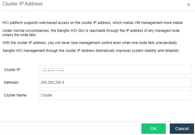
-
And then click OK.
-
Modify the IP address of the management communication port, and then configure information about the cluster IP address.

Management Port Switch without IP Address
Description
Through the management interface, the cluster can manage the node. When the management network is re-planned, it can switch the management network port without IP address in batches to realize the smooth switching of the management network.
Precautions
- When the cluster is configured with a cluster IP and the management interface is on the same network segment, it is not supported without IP switching. Instead, only a management interface with IP switching is allowed.
- After modifying the management interface for the non-cluster controller without IP and making the non-cluster controller offline, log in to the non-cluster controller separately to switch the management interface back. You need to log in to the non-cluster controller background to call the interface for switching the management interface and switch the management interface back to the network.
- If the new management interface’s IP information is empty, the old network interface’s information will be brought to the new NIC when switching the management interface.
Prerequisites
None.
Steps
- Navigate to Nodes > Communication Interfaces > Management Interface, and click Settings.
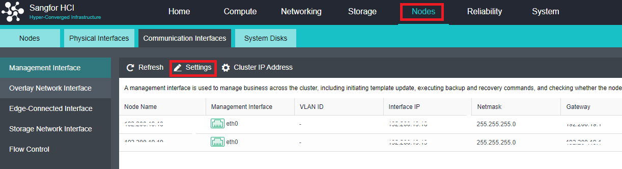
- Select the new management communication interface, and click OK.
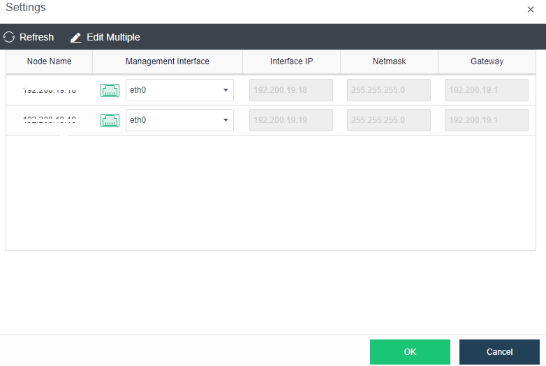
- Click OK on the prompt.
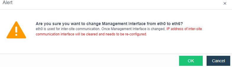
- After clicking OK, select whether to switch the management interface with an IP address in the pop-up confirmation option box and click OK.
Modifying the IP Address of the Arbitration Node
Description
When you need to adjust the network configuration of the stretched cluster, you need to synchronously modify the IP of the witness node so that it can communicate with the IP of the HCI cluster normally.
Precautions
Before modifying, you need to confirm whether there are data balancing and data rebuilding tasks on the HCI platform. If these tasks are running, you need to wait for the end of the task before modifying them.
Prerequisites
None.
Steps
- Enter the WEB admin console of the witness node and change the IP of the arbitration interface of the witness node to the new IP.
- Check whether the IP of the newly modified quorum node is connected to the HCI cluster network and ensure that the quorum node can communicate with the HCI cluster network normally.
- Log in to the HCI cluster, click Modify Witness Node IP in the Nodes quorum node, and fill in the new quorum IP so the HCI cluster can connect to the new IP.
Data Communication Port (VXLAN) Modification
Description
- The user needs to modify the physical network port corresponding to the VXLAN network or the IP address of the physical network port corresponding to the VXLAN network due to network planning changes.
- If a conflict with the VXLAN default interface due to the deployment of applications such as containers, the interface used by the VXLAN network needs to be modified.
Precautions
- Modifying the physical interface, IP address, or interface corresponding to the VXLAN network will cause the VXLAN network to be temporarily interrupted. Please modify the configuration during the downtime window.
- The overlay network interface requires a Gigabit (or 10 Gigabit) network interface and a Gigabit (or 10 Gigabit) switch for interconnection. (When only two nodes exist, the overlay network interface can be directly connected). To improve the interface bandwidth and redundancy of the Overlay Network Interface, it is recommended to configure the aggregation interface as the Overlay Network Interface. In this case, the peer switch must be configured with the corresponding aggregation mode.
- To obtain high network forwarding performance, it is recommended to set the management communication port and Overlay Network Interface (VXLAN) to different interfaces.
- Direct aggregation of two interfaces with different roles is not supported. You can cancel the role of one interface before aggregation. Example: Cannot directly aggregate eth0 (management interface) and eth1 (VXLAN interface). The VXLAN interface can be adjusted to eth2. At this time, eth0 (management interface) and eth1 (no role) can be aggregated.
Steps
- Using an aggregated interface is recommended: Navigate to Nodes > Physical Interfaces, click Add multiple aggregated interfaces, and select two network interfaces—for example, eth2 and eth3. The aggregation mode is recommended based on the MAC or IP address load.
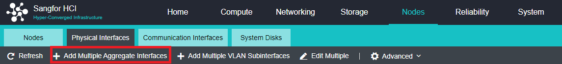
- Find the Overlay Network Interface and click Edit Configuration to enter the configuration page to modify the Overlay Network Interface.
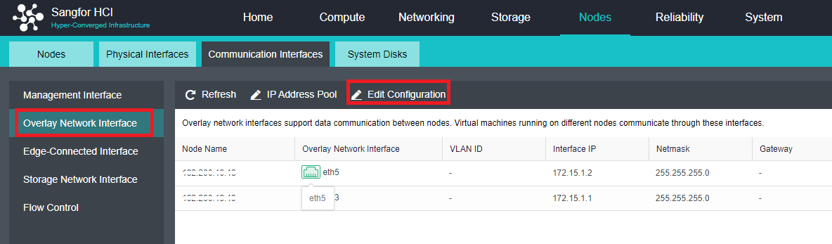
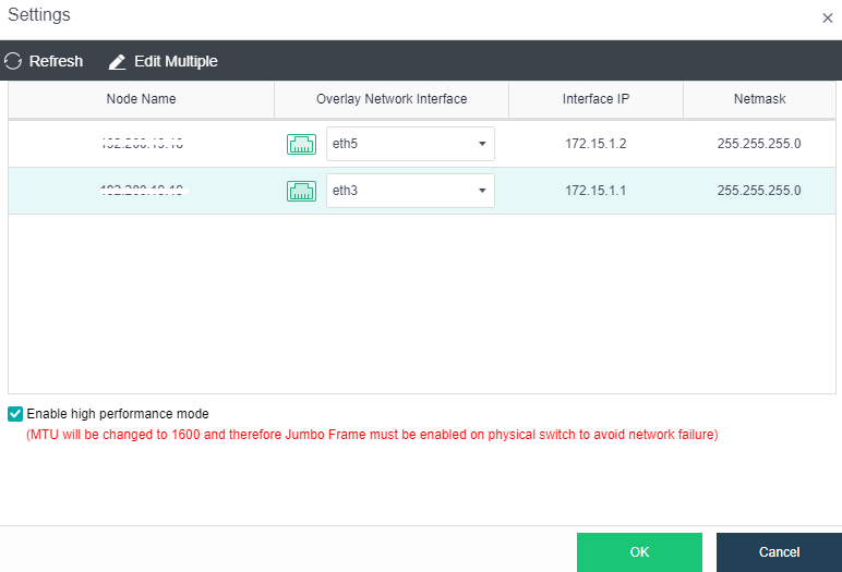
- By checking the Enable high performance mode checkbox, the MTU of the interface of the HCI node will be set to 1600 bytes so that the data encapsulated by VXLAN will not be fragmented when sent to the physical network, which can significantly improve the virtual network forwarding performance. At this time, the physical switch at the opposite end must enable Jumbo Frame.
Health Check
Description
- After the platform is deployed, you need to check whether the configurations in the cluster are correct.
- When troubleshooting, use the Health Check function to check whether the platform environment is normal.
Precautions
- Using the health check function of the cluster environment will impact the performance of the existing business system you are running. It is recommended that you run it when during non-peak business hours.
- Before performing dangerous operations on the cluster, such as powering off the node, you must first use the health check to check whether the cluster status is normal. The operation can be performed only when everything is normal.
Prerequisites
None.
Steps
- On the HCI, click Health Check.
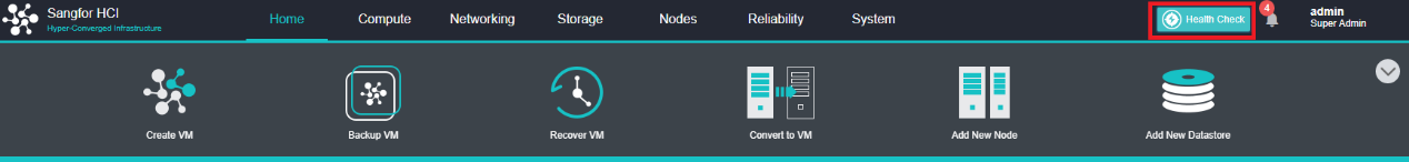
- Select the items that need to be detected, and click Start. After the checking is complete, the interface will obtain a current cluster health index score, and mark the alert items and fault items in the list.
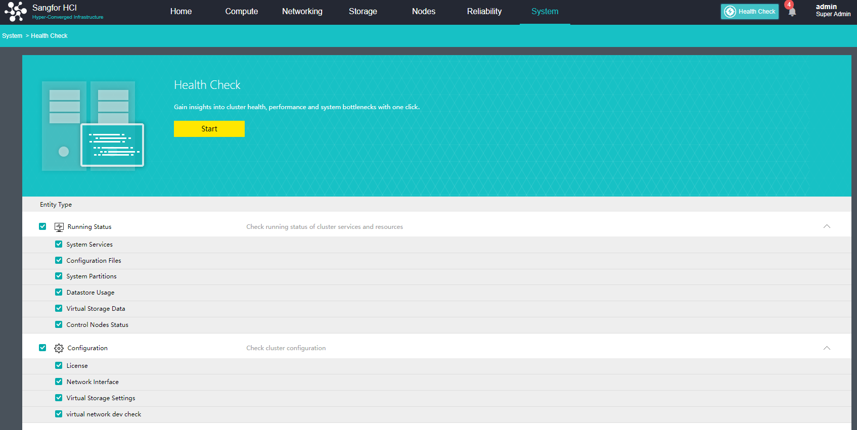
System Diagnostics
Description
In the regular daily operation and maintenance process, you can use the system diagnosis function to execute some common Linux commands on the HCI platform to troubleshoot problems quickly.
Precautions
None.
Prerequisites
None.
Steps
- Navigate to System > System Diagnostics.
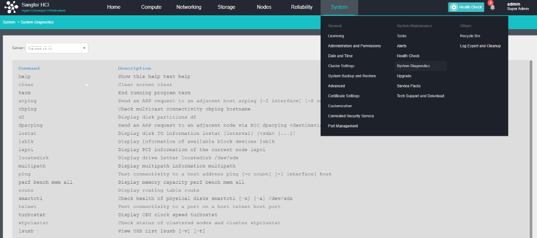
- Switch the node that needs to execute the command and execute the command.
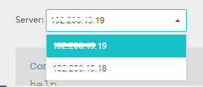
Modify Platform Date and Time
Description
When the platform time is inconsistent with the real-time, the platform date and time need to be modified.
Precautions
None.
Prerequisites
The platform needs to communicate with the external NTP server network.
Steps
- Navigate to System > Date & Time.
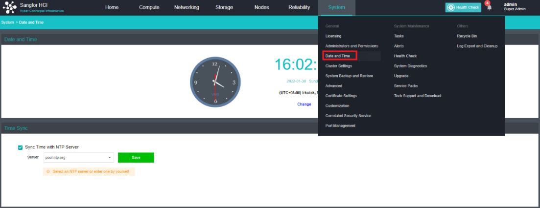
- Click Change to modify the time.

- Here you can fine-tune the time manually or configure the time of the platform by Sync with Local PC. It is also possible to modify the time zone of the platform.
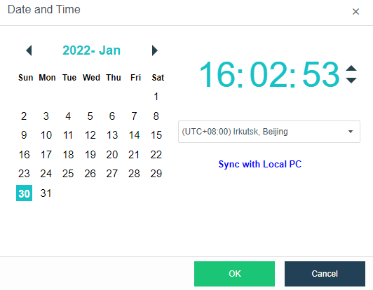
- If you want to synchronize the platform time with the internal NTP server, you only need to check the Sync Time with NTP server checkbox and modify the Server, then click Save.

System Backup and Restore Configuration
Description
- Back up the relevant configuration of the system and restore it in case of any problems occur. System configuration includes:
- aSV cluster configuration.
- User (including user password, please be careful when selecting).
- Virtual machine backup strategy.
- High Availability (HA) configuration.
- Automated Hot Add Configurations
- User Experience Improvement Program.
- Time synchronization settings.
- Alarm conditions.
- Resource Scheduling configuration.
- Restore the NUMA configuration.
- The platform saves system logs for 30 days by default, and you can manually save the system logs locally.
Precautions
- If you need to restore the related configuration of the cluster, you need to contact Sangfor technical support.
- System backup deletion only supports the deletion of all backup files but does not support the deletion of a single backup file.
Prerequisites
None.
Steps
- Navigate to System > System Backup and Restore.
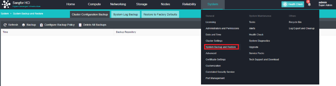
- Click Cluster Configuration Backup to set the backup policy and create or delete backups.
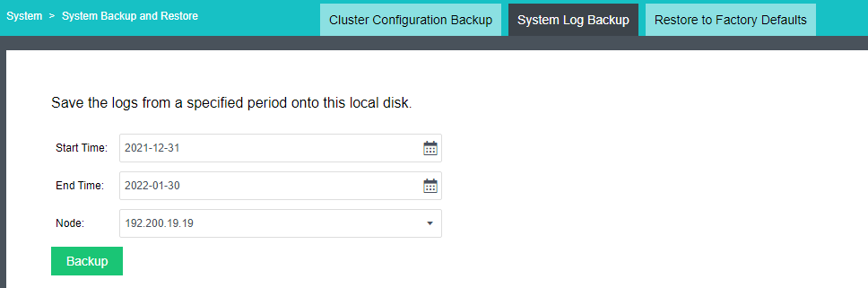
- Click System log backup to back up the system log locally.
Restore to Factory Defaults (High-Risk Operation)
Description
The entire platform can be formatted by Restore to Factory Defaults.
Caution:
Please operate with caution.
Precautions
- After restoring the factory settings, all the nodes will be restored to the factory state, and the aSV will be automatically removed. The aSV needs to rejoin.
- At the same time, all the parameter information of the aSV configuration will also be restored to the initial state, including aSV cluster configuration, users, virtual machine backup policy, user experience plan, date and time, and alert conditions.
- The virtual machines in the remaining local storage on the system disk will not be deleted.
Prerequisites
Factory reset will format the platform and ensure there are no virtual machines on the platform before operating.
Steps
- Navigate to System > System Backup and Restore > Restore to Factory Defaults on the console.
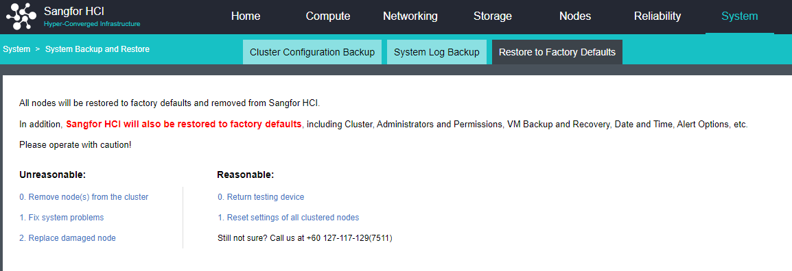
- The factory settings can be restored only when the test equipment is returned and the cluster configuration is restored defaults.
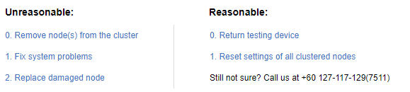
- Click Return Testing Device, and a message window will pop up to warn the user of the risk of restoring to factory settings. If the user insists on restoring the factory settings, you can click Continue, and the system will pop up the Warning window again to warn you of the risk of restoring the factory settings. If the user insists on restoring the factory settings, you can click Continue, and the system will pop up the Warning window again to warn you of the risk of restoring the factory settings. If the user insists on restoring the factory settings, enter the password in the input box in this window, and click OK. The system will immediately restore to factory defaults.
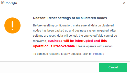
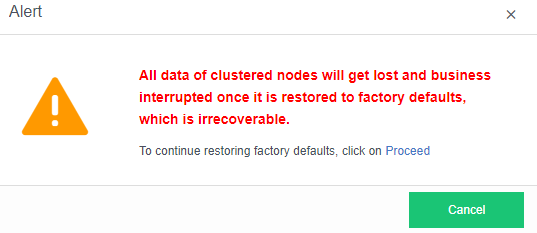
CPU Overcommitment Configuration
Description
HCI uses virtualization technology to achieve overcommitment and multiplexing of CPU resources. However, suppose the overcommitment is too high. In that case, the configurable resources increase, and the actual usable resources do not increase. This may lead to virtual machine resource preemption, resulting in the virtual machine not functioning properly. In regular operation, you can set the CPU overcommitment limit to avoid the impact on the platform virtual machine due to excessive overcommitment. In the new scenario, the default overcommitment ratio is 200%. The default overcommitment ratio is unlimited.
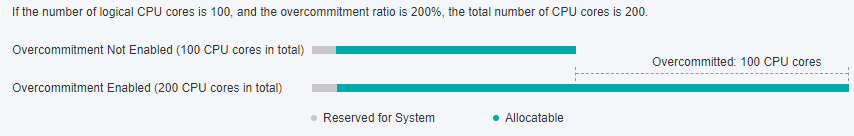
Precautions
- There are two types of CPU overcommitment: 100% to 500% and unlimited.
- The virtual machine will not function properly when the actual CPU usage exceeds the computing CPU capacity.
- When the actual configuration CPU of the running virtual machine exceeds the configurable CPU, the virtual machine will be unable to power on.
- The larger the CPU overcommitment ratio, the more virtual machines can start. If the ratio is too high, the virtual machine may have latency. Please set it carefully. It is not recommended to enable CPU overcommitment in core business scenarios.
Prerequisites
None.
Steps
- Navigate to System > Cluster Settings > CPU Overcommitment Settings.
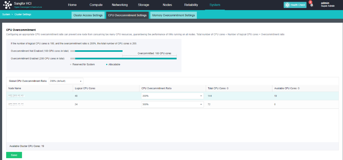
- Configure CPU overcommitment.
Memory Overcommitment Configuration
Description
Configure the memory over-provisioning parameters allowed by the host to meet the scenarios where the configurable memory exceeds the physical memory.
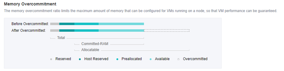
Precautions
- When the actual memory used exceeds the committed-RAM capacity, the virtual machine will not be able to power on.
- When the actual configured memory of the running virtual machine exceeds the configurable memory, the virtual machine will not be able to power on.
- After the active upgrade, the memory guarantee mechanism and the overcommitment alert need to restart to take effect.
- The larger the memory overcommitment ratio, the more virtual machines can be started. If the ratio is too high, the virtual machine may have latency, so please set it carefully. It is not recommended to enable memory overcommitment in core business scenarios.
- If the memory overcommitment ratio of the node before the upgrade is greater than 300%, it will be forced to be set to 300% after the upgrade.
Prerequisites
None.
Steps
- Navigate to System > Cluster Settings > Memory Overcommitment Settings.
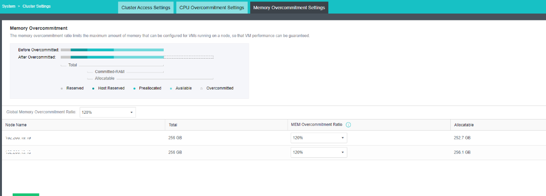
- Configure memory overcommitment.
VM Escape Detection
Description
Malicious programs running on virtual machines can exploit the vulnerabilities of virtualization to break the boundaries between virtualization permissions and data isolation and control the attack behavior of the hypervisor and the host (Host), called virtual machine escape.
Sangfor HCI analyzes virtual machine behavior, finds suspicious events, and outputs alert logs for auditing. Use the sandbox mechanism to implement multi-level protection to minimize the permissions of the protected object so that even if the attacker successfully exploits the vulnerability, the ability is limited and not enough to perform malicious behavior.
Precautions
Enabling virtual machine escape detection has a certain performance consumption, so you need to be careful. It is recommended to use this function when the business system is required to enable it. It is not recommended to enable it if it is not required.
Prerequisites
None.
Steps
- Enter the System > Advanced interface, and check or uncheck the VM Escape Detection checkbox to enable or disable it.
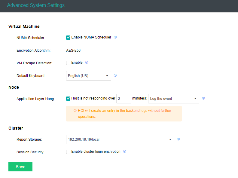
- Click Save to save the configurations.
Correlated Security Service
Cyber Command Correlation
Description
Sangfor Cyber Command (CC) supports calling the HCI platform and obtains the traffic in the HCI cluster in real-time through mirroring, conducts traffic monitoring and analysis, and realizes risk prediction and prevention before failure, and timely detection and processing of failure. Supports functions such as automatic isolation of infected virtual machines, automatic storage snapshots for risky virtual machines, and automatic shutdown/suspension of risky virtual machines.
Precautions
- After HCI is connected to CC, the virtual machine list can be automatically synchronized to the CC. You do not need to manually enter the IP.
- The storage snapshot scenario requires that the HCI cluster supports the aSAN storage snapshot function. Otherwise, the CC does not support using the correlated snapshotting function.
- CC takes snapshots of the virtual machines in the consistent snapshot group and snapshots of the entire consistent snapshot group.
- Support connecting NFV devices on HCI to CC.
Prerequisites
This function requires CC and HCI to activate corresponding authorization at the same time.
Steps
- The partner service is not enabled by default in HCI. It is necessary to ensure that the HCI has authorization. Enter the System > Correlated Security Service interface, and click Enable Correlated Security Service to enable the function.
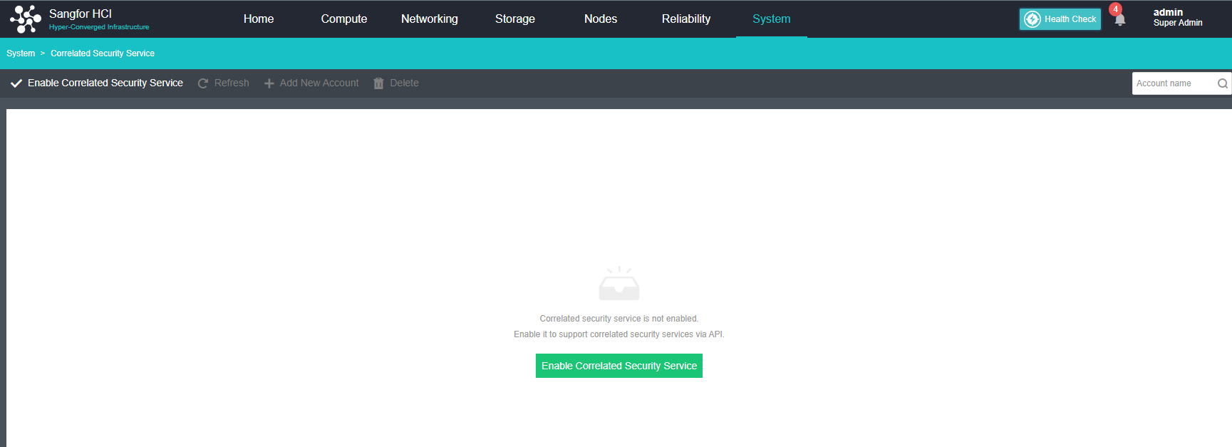
- Click Add New Account to add an account that can call the corresponding API interface.
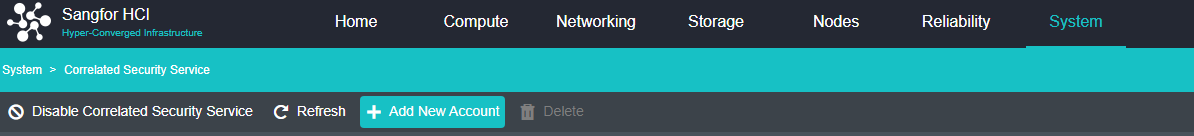
- Enter information such as the Account Name, Password, Correlated Platform, and Permissions: Third-party security service, PAAS, CC, etc. Select CC here, and the correlated service modules of CC will be automatically identified below. Multiple modules can be selected by yourself.
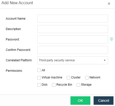
- Add HCI in the Authentication Account position, write the service account created on the HCI above, and wait for the assets to be synchronized.
- Create a linkage policy in the CC platform’s Response Toolbox > Linkage Response.
Correlate PAAS
Description
Sangfor Container Cloud KubeManager platform supports connection to Sangfor virtual storage aSAN or file storage NFS for persistent data storage. Users can store business data outside the application Pod. When the application Pod fails, the application data can be protected from Influence. To connect the KubeManager platform with Sangfor NFS or aSAN storage, you need to use the PAAS linkage function in the partner service.
Precautions
None.
Prerequisites
- The HCI platform requires aSI authorization.
- The management plane of the KubeManager platform and the HCI can communicate.
Steps
-
Log in to the HCI platform, select System > Correlated Security Services, and click Add New Account.
-
Customize account information:
- Account Name: Service account name, for example: simon.
- Description: Account description, for example: simon-paas.
- Password: Service account password.
- Correlated Platform: PaaS.
- Permissions: Check Storage (checked by default).
-
After clicking OK, the service account is added.
-
Log in to the KubeManager platform, switch to the cluster where the storage server needs to be added, select Storage > Storage Server, and click Add Storage Server.
-
Enter the name of the storage server, select the corresponding storage type, and configure the basic information of the server.
VMware Management
Adding vCenter
Description
The HCI platform manages VMware by adding the vCenter platform. Manage all VMware virtual machines on the HCI platform, and configure VMware virtual machines for backup on the HCI platform
Precautions
None.
Prerequisites
- The HCI platform needs to enable the authorization of heterogeneous management.
- Support vCenter5.0, vCenter5.1, vCenter5.5, vCenter6.5, vCenter6.7, vCenter7.0、vCenter7.0.1, and vCenter7.0.2 versions. Other versions are not supported.
- Ensure that the management IP of the HCI platform and vCenter can communicate normally.
- When adding a vCenter, the vCenter account needs to have administrator privileges.
Steps
- Navigate to the Nodes > VMware vCenter.
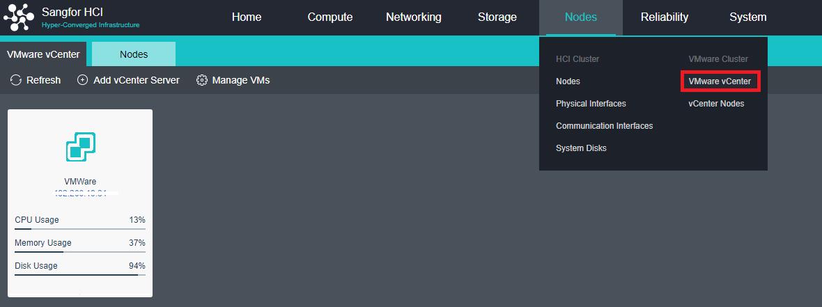
- Configure the information, such as the name, vCenter address, user name, password, and interface, and click OK after the configuration is complete.
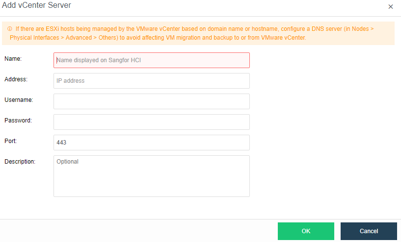
- After the configuration is complete, you can see the vCenter status in Nodes > VMware vCenter.
Managing VMware Virtual Machines
Create A New Virtual Machine
Description
HCI supports operations such as creating, deleting, starting, shutting down, suspending, restarting, powering off, and opening the console for VMware.
Precautions
None.
Prerequisites
- To shut down the virtual machine on VMware, you need to install VMtools on the VMware virtual machine.
- To open the console of the VMware virtual machine, you need to install the VMware Remote Console tool.
- To create a new VMware virtual machine on the HCI platform, you need a corresponding virtual machine template on the VMware vCenter.
- For VMware virtual machine, first, install the Sangfor vmTools, and then backup and restore the IP to HCI.
Steps
- On Compute > VMware vCenter, click New.
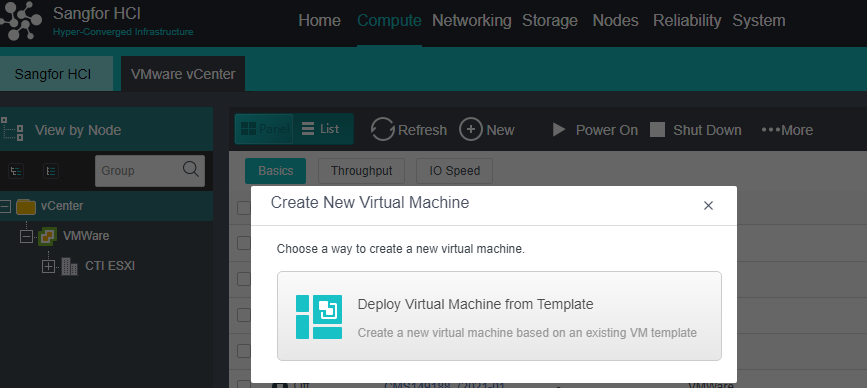
-
Select Deploy Virtual Machine from Template.
-
Select a virtual machine template and click Next.
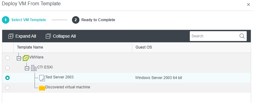
- Configure the Name, Group, Run Location, Datastore, and hardware-related information of the virtual machine. Click OK after the configuration is complete.
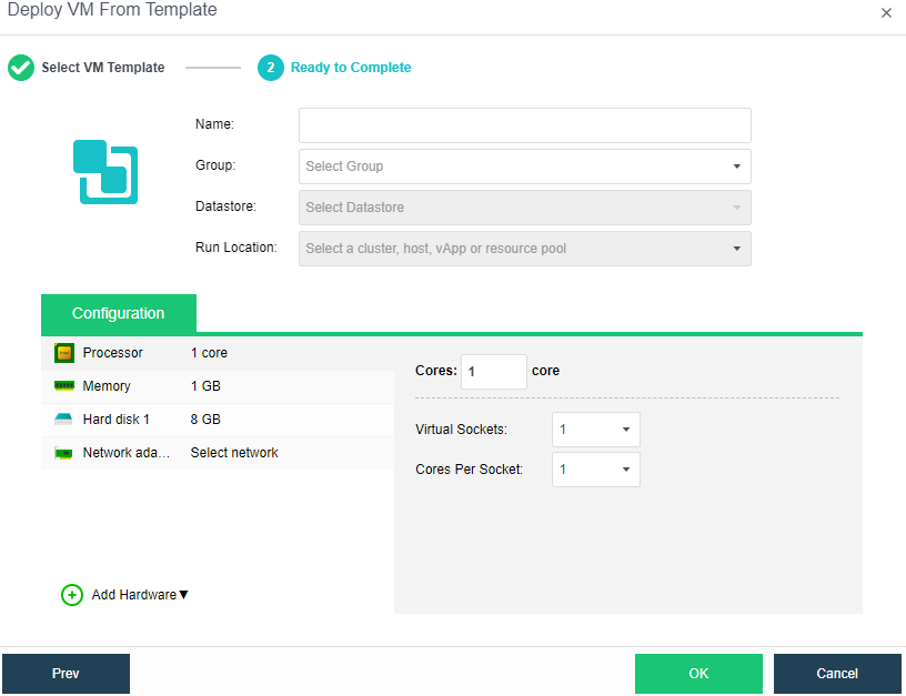
Deleting VMware Virtual Machine
Description
HCI supports operations such as creating, deleting, starting, shutting down, suspending, restarting, powering off, and opening the console for VMware.
Precautions
Confirm that the virtual machine is no longer in use and can be deleted from the VMware vCenter. After the deletion, the virtual machine cannot be restored.
Prerequisites
None.
Steps
- Find the virtual machine to be deleted in Compute > VMware vCenter, click the More button, and click Delete.
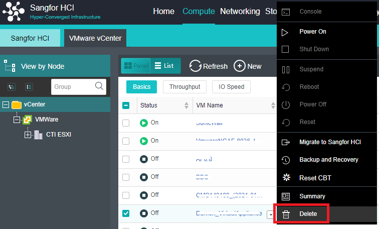
- After the task is complete, the virtual machine has been successfully deleted.
Virtual Machine Power On and Off Operations
Description
HCI supports operations such as creating, deleting, starting, shutting down, suspending, restarting, powering off, and opening the console for VMware.
Precautions
After installing vmTools, you need to restart the virtual machine. You cannot directly power off. Otherwise, problems such as blue screens and abnormal drivers may occur.
Prerequisites
- To shut down the virtual machine on VMware, you need to install VMtools on the VMware virtual machine.
- To open the console of the VMware virtual machine, you need to install the VMware Remote Console tool.
- To create a new VMware virtual machine on the HCI platform, you need a corresponding virtual machine template on the VMware vCenter.
Steps
- Click the More button on the selected virtual machine.
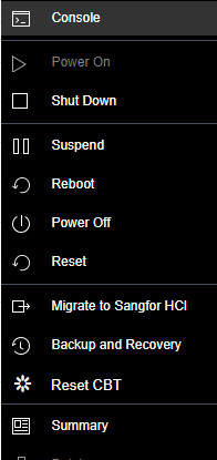
- Just follow the menu and operate as per needed.
Backup of VMware Virtual Machines
Description
HCI supports backing up VMware virtual machines to its platform and supports restoring the backed up virtual machines to the HCI platform or VMware vCenter.
Precautions
None.
Prerequisites
HCI requires the authorization of the number of backup virtual machines to be enabled.
Steps
- Under Compute > VMware vCenter, select the virtual machine that needs to be backed up.
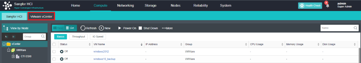
- Click More and select Backup and Recovery.
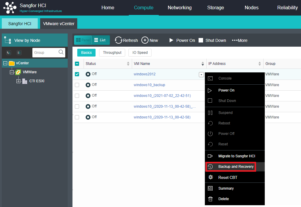
- After entering the backup interface, click Backup.
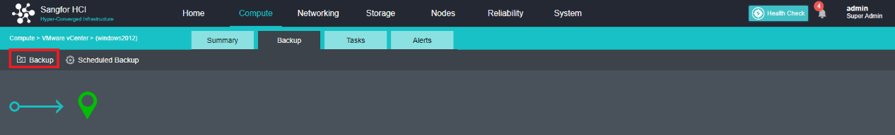
- Configure the Backup Name and Destination Datastore, check the Enable VSS and Full backup checkboxes and click OK to start the backup.
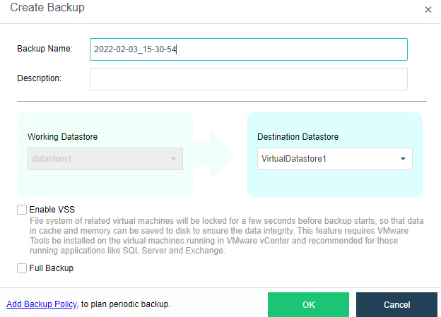
Restoring VMware Virtual Machines
Description
HCI supports backing up VMware virtual machines to the HCI platform and supports restoring the backed up virtual machines to the HCI platform or VMware vCenter.
Precautions
VMware virtual machines automatically install vmTools when the HCI platform is restored from backup.
Prerequisites
VMware virtual machines have been backed up.
Steps
- Find the virtual machine to be backed up in Reliability > Scheduled Backup/CDP > VMware Backups.
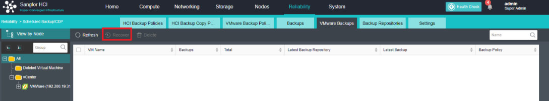
-
Click Recover to enter the recovery confirmation interface.
-
Select the recovery location, choose recover to HCI or VMware vCenter, and click OK.
-
Click OK again to start the recovery.
Migrating VMware Virtual Machines
Description
The HCI platform supports migrating the virtual machine of the VMware vCenter to its platform for running. It can be migrated in the power-on state, and the virtual machine of the VMware vCenter can be turned off in the final stage to complete the migration.
Precautions
-
If a VMware virtual machine migrated to HCI is back to VMware, the vmTools need to be uninstalled. The Sangfor vmTools will disable VMware’s VMtools.
-
In Centos 7.0, 7.1, and earlier versions, after P2V migration of a virtual machine in the form of EFI firmware on the VMware platform to the HCI platform, the target virtual machine starts for the first time. Still, it may enter the EFI shell for the second boot. It can be solved by restarting.
-
When a VMware virtual machine is migrated to the HCI platform, the vmTools will be installed automatically.
-
Supported VMware versions:
VMware 5.0, VMware 5.1, VMware 5.5, VMware 6.0, VMware 6.5.
aCloud 5.8.7 R1 and later supports VMware 6.7.
-
If the migration is canceled during the migration process, HCI will not delete the migrated virtual machine. The virtual machine can be viewed under Compute and needs to be deleted manually.
Prerequisites
None.
Steps
- Find the virtual machine that needs to be migrated to the HCI platform in Compute > VMware vCenter, and select Migrate to Sangfor HCI.
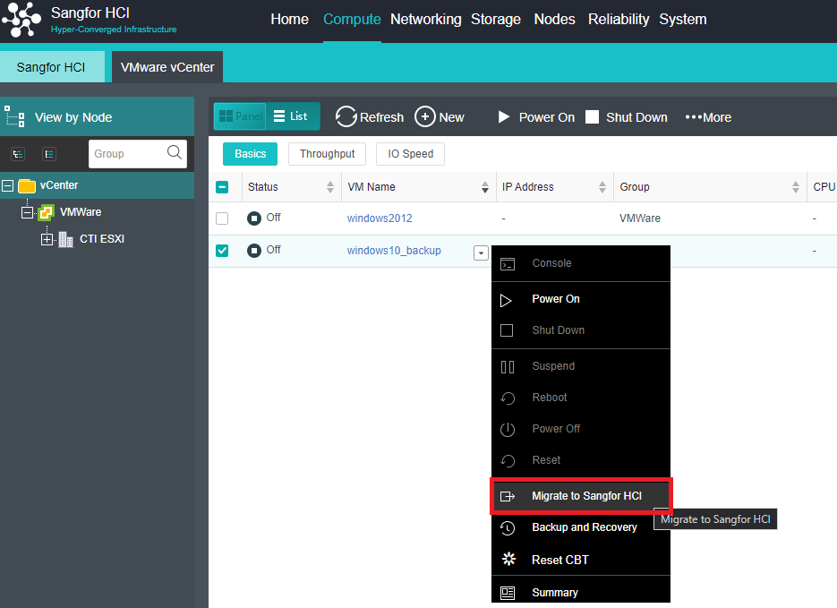
- Configure migration information such as Name, Group, and Datastore.
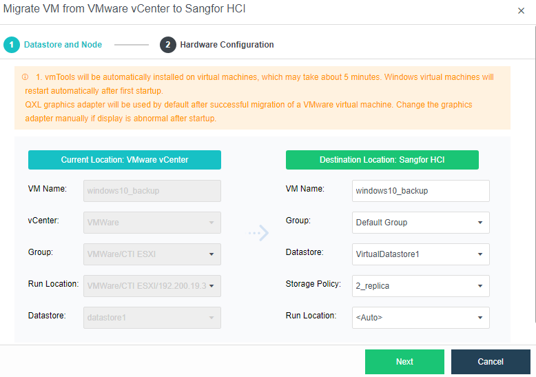
- Click Next to enter the virtual machine hardware configuration after migration, which supports the configuration of NIC connection, Adapter Model, MAC address, IP address, etc. If the IP of the original VMware virtual machine has been configured, the relevant information will be automatically configured. If the IP of the VMware virtual machine is not configured, you need to configure it manually.
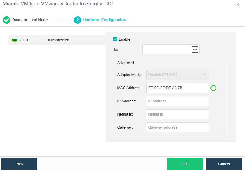
- After the configuration is done, click Confirm to start the migration.
Witness Node Failure Handling (high-risk operation)
Description
When the witness node in the cluster goes offline due to a physical failure, it needs to be replaced with a new node.
Precautions
- It is required that the configuration of the new witness node cannot be lower than that of the original failed witness node.
- It is recommended that the capacity of the quorum disk of the new witness node is the same as that of the old witness node.
- The management IP address of the replacement witness node cannot be the same as the original witness node.
Prerequisites
- The replacement witness node system has been installed and IP addresses have been configured.
- The IP address of the replaced witness node system can communicate with the HCI cluster normally.
Steps
- Find the failed witness node in Nodes > Nodes, and click Replace Host.
- Enter the IP and password of the new witness node.
After replacing the witness disk, confirm the configuration and save it.
Version Upgrade (high-risk operation)
Description
Upgrade the version of the HCI cluster.
Precautions
- If the active upgrade fails in any form, please do not close the maintenance mode without authorization, and do not roll back and retry without authorization. Please keep the complete site and contact technical support for processing.
- If the current and target versions support active upgrades, please ensure that the upgrade occurs when the customer’s business volume is relatively idle. During the upgrade process, the TPM value of the database will drop slightly, and it will take about 1 minute to recover.
- After the active upgrade is successful, turn off the maintenance mode manually.
- The hot upgrade will temporarily interrupt the USB mapping of the virtual machine using USB mapping for 10s. Please confirm if any user’s business depends on USB.
- During the upgrade process, a page may prompt the communication to be timed out. You cannot move the upgrade page. Only when the page prompts you to retry, manually click to retry.
Prerequisites
None.
Steps
For specific Precautions and Steps, please refer to the upgrade plan of the current version. For the upgrade plan, please log in to the Sangfor Community > Self-Service > Software Download page to find the upgrade package of the corresponding version and upgrade plan.
Enter Maintenance Mode
Description
The administrator can use the maintenance mode when the administrator needs to power off a single node in the hardware maintenance scenario. After the maintenance mode is activated, the system will first migrate the services on the platform to other nodes to ensure that the replacement process will not affect the business. The maintenance mode can achieve the effect of self-operation and maintenance.
Precautions
- The cluster controller does not support the Enter Maintenance Mode. If you need to maintain the cluster controller, please switch to other nodes as the master first.
- If there are nodes offline in the environment, you cannot enter the maintenance mode.
- There is a task in progress on the node to be maintained. You cannot enter the maintenance mode temporarily. You need to wait for the task to complete before entering.
- Currently, only one node is allowed to enter maintenance mode at the same time.
Prerequisites
None.
Steps
- In Node, click More and choose Enter Maintenance Mode.
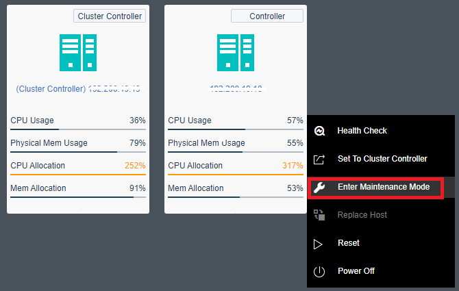
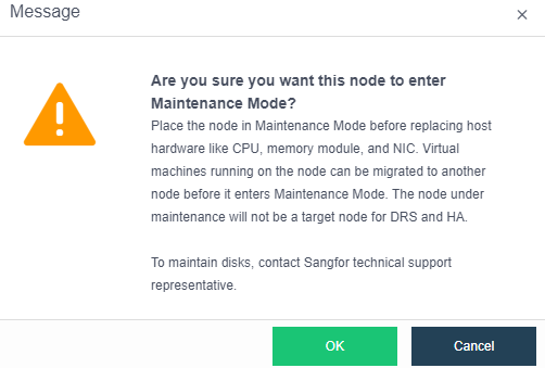
- After entering the password, select OK to enter the node maintenance mode. The system will isolate the node.
- The node has successfully entered maintenance mode, and you can start to perform O&M operations such as powering off the node.
Virtual Machine Disk Encryption
Description
Enabling virtual machine disk encryption increases the security of virtual machine disks. The encryption protection of images and snapshots can be achieved by encrypting the virtual machine disks during the detection of equal protection.
Precautions
- Virtual machine disk encryption supports AES 256 symmetric encryption algorithm.
- One encryption option per virtual machine. After enabling the encryption, the entire virtual machine is encrypted.
- One virtual machine has one key. After encryption, all disks have the same key.
- After virtual machine disk encryption is enabled, it cannot be canceled.
- After the virtual machine disk is encrypted, it is irreversible.
- The encrypted disk virtual machine None method for disk encryption can be used to export, clone, and deploy templates.
- The platform encryption function adopts a pure soft encryption method. Customers do not need to purchase additional hardware, such as encryption cards and encryption machines.
- Key management functions are all implemented in the platform by simulating KMS.
- Encryption of a virtual machine is performed when it is created or in the shutdown state. To encrypt a virtual machine with an existing service, you must do it during non-business hours.
- After the virtual machine is encrypted, the disk data read and write needs to be encrypted and decrypted, which has a certain performance consumption. It is necessary to turn on the virtual machine encryption function carefully.
Prerequisites
None.
Steps
- Navigate to System > Advanced to view the Encryption Algorithm.
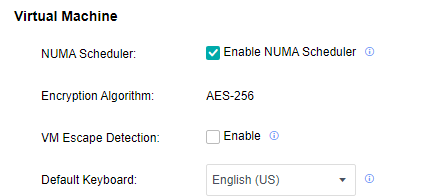
-
Open the Compute page and make sure that the virtual machine to be encrypted is powered off.
-
Click More > More > Encrypt VM to encrypt the virtual machine.
-
After complete encryption, the Compute page will display a flag that the virtual machine has been encrypted.

Recycle Bin
Description
Users delete virtual network devices, virtual machines, shared disks, etc., on the web admin console. They will be temporarily stored in the recycle bin to prevent data loss due to misoperation. The files in the recycle bin support recovery and complete deletion. If you do not manually delete or empty the recycle bin, the files in the recycle bin will be retained for 30 days by default and then completely deleted.
Precautions
- Empty the recycle bin entirely is a high-risk operation. Please confirm that the files in the recycle bin are no longer used before performing the operation of completely deleting or emptying the recycle bin.
- The network devices, virtual machines, and shared disks in the recycle bin can be restored and completely deleted in the web admin console. The residual files (virtual machine backup) can only be completely deleted in the web admin console and cannot be restored.
- To restore the files in the recycle bin, only the files will be restored, and the connection relationship between the devices will not be restored.
Steps
- Enter the System > Recycle Bin interface, select the file type to be restored (Virtual Machines, Basic Network Devices, Network Security Devices, Shared Disks), select the file, and click Restore.
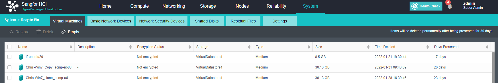
-
Click Delete to completely delete the network device, virtual machine, or virtual machine shared disk. You cannot restore it after deletion. (High-risk operation)
-
Clicking Empty will completely delete all files under the file type, and you cannot restore it. (High-risk operation)
Residual Information Protection
Description
The HCI residual information protection function allows users to completely erase existing data during resource recycling. Equal protection or secret-related scenarios require that the storage space supports data erasure during recycling to ensure important data security. Users can customize the number of overwrites according to regulatory requirements or business needs and choose to completely erase existing data during resource recycling.
Precautions
- CPU and IO resources will be occupied when using the data erasure function. Therefore, the erasing process will take a certain amount of time, so performing it when the business is idle is recommended.
- After erasing, the data cannot be recovered.
- After the erasure rate is modified, it will take effect for all data erasure tasks. The actual rate will be dynamically adjusted according to the storage IO performance and busyness.
Steps
-
Enter the System > Recycle Bin interface, and click Settings to configure the data erasing rate and erasing speed.
-
If Data Erasure is enabled, when deleting virtual network devices, virtual machines, shared disks, residual directories in the recycle bin, and deleting virtual disks of virtual machines, the data will be erased at the same time. Keep data safe.
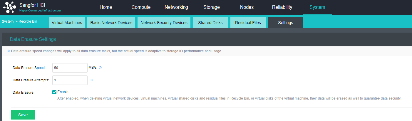
- Click the Virtual Machines tab. Select the virtual machine and click Delete or click Empty. The operation will prompt the option: Delete the backups of the virtual machine. Backups will be stored in Recycle Bin for 30 days before being permanently deleted. Check this checkbox and enter the HCI administrator password to completely erase the virtual machine’s data.
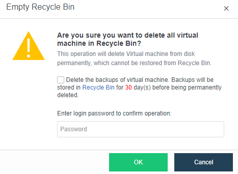
Reporting Location Management
Description
The cluster report data records the trend data of each resource in the cluster and is used by users to query the trend data of 1 hour, 24 hours, and 1 month. In the cluster mode, it is possible to change the data datastore to achieve high availability of report data.
Precautions
Only support system disk local storage, virtual storage (2 nodes virtual storage volumes are not supported), iSCSI storage, and FC storage.
Prerequisites
None.
Steps
Enter the System > Advanced System Settings interface, select the datastore, and click Save.
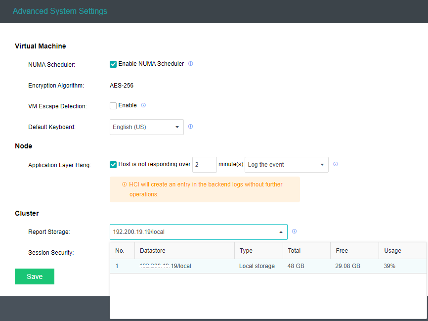
Chinese/English Language Switching
Description
Sangfor HCI platform supports language switching from Chinese to English or vice versa to fulfill the scenarios of operation and maintenance personnel using different languages.
Precautions
- HCI6.8.0 and above support Chinese/English language switching but do not support region switching for the time being.
- NFV, aSEC, and VDC components do not support language switching. Please use the corresponding international version component package.
- User-customized content, such as virtual machine name/description, virtual network device name/description, etc., does not support language switching.
- Support sessional language switching. When multiple users are online, they can choose the preferred Chinese/English interface.
Prerequisites
None
Steps
Click on the language located at the top right to switch.
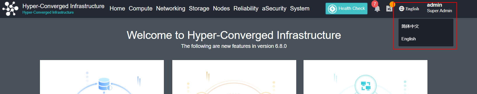
Platform Operation and Maintenance
Operation and Maintenance tools/modules
Daily Operation and Maintenance Module
Alert Monitoring
Application Scenario
It is suitable for the operation, maintenance, and monitoring scenarios of the HCI platform. The administrator can view the platform’s alert information on the HCI console’s home page and solve the problem in time according to the alert information.
Steps
| Alert module | Monitoring item | Common alarm | Emergency alert |
|---|---|---|---|
| Node | Host swap partition occupancy | For 10 minutes, the swap partition occupies more than 10% | |
| Node | Host CPU usage | CPU usage exceeds 90% for 10 minutes | |
| Node | host CPU temperature | Abnormal temperature for over 10 minutes. | |
| Node | host CPU frequency | Host CPU throttling | |
| Node | Host memory usage | Memory usage exceeds 90% for 10 minutes | |
| Node | Memory frequency | Memory underclock. | |
| Physical network | Host network port error packet | The packet error rate exceeds 10% for 10 minutes | |
| Physical network | Node interface status | Node interface dropped | |
| Physical network | Cluster Node status | Node offline | |
| Physical network | Data communication incoming interface (VXLAN) status | The data communication incoming interface (VXLAN) is unavailable. | |
| Physical network | Host NIC working status | The host NIC works abnormally for 10 minutes. | |
| Physical network | Node NIC traffic status | Host NIC traffic reaches 90% of the upper limit for 10 minutes | |
| Physical network | NIC driver firmware compatibility | Incompatible NIC driver firmware | |
| Physical network | NIC status | Damaged NIC | |
| Physical network | NIC optical module status | NIC optical module is abnormal | |
| Storage | Store IO status | Storage IO busy for 10 minutes | |
| Storage | Backup repository state | Backup repository IO is busy | |
| Storage | Store IO latency status | Storage IO latency is high for 10 minutes | |
| Storage | Store the connection status with the node | The storage is disconnected from the node | |
| Storage | Storage state | Abnormal storage status | |
| Storage | RAID card status | RAID status | |
| Storage | Storage Occupancy Threshold | More than 90% | |
| Storage | Storage Backup Repositories Occupancy Threshold | More than 90% | |
| Virtual Machine | virtual machine memory usage | Memory usage exceeds 90% for 10 minutes | |
| Virtual Machine | Virtual machine CPU usage | CPU usage exceeds 90% for 10 minutes | |
| Virtual Machine | Virtual machine image file | Corrupted virtual machine image file | |
| Virtual Machine | Virtual Machine Backup Status | Virtual machine backup fails | |
| Virtual Machine | Virtual machine and external network connectivity | The virtual machine cannot communicate with the external network | |
| Virtual Machine | Number of session connections on a single incoming interface of a virtual machine | Lasts for 3 minutes, more than 100000 sessions | |
| Virtual Machine | Virtual machine state | Abnormal shutdown or restart of virtual machine | |
| Virtual network | Virtual network device CPU usage | CPU usage exceeds 90% for 10 minutes | |
| Virtual network | Virtual network device image file | Corrupted virtual network device image file | |
| Virtual network | Router operating status | Router fails | |
| Virtual network | Virtual network device ALG usage | ALG usage exceeds 90% for 30 seconds | |
| Virtual network | Virtual network device and external network connectivity | The virtual network device cannot communicate with the external network | |
| Cluster | Reminder of regular inspection frequency | Once a month | |
| Cluster | Licensing status | Licensing expired | |
| Cluster | License key status | The license key status is abnormal |
-
It is recommended to set email alerts or SMS alerts to improve the efficiency of getting alerts. For a detailed configuration of alert notifications, refer to the Chapter 10.5 Alert Options.
-
Log in to the HCI console, and navigate to System > System Maintenance > Alerts to enter the Alerts interface.
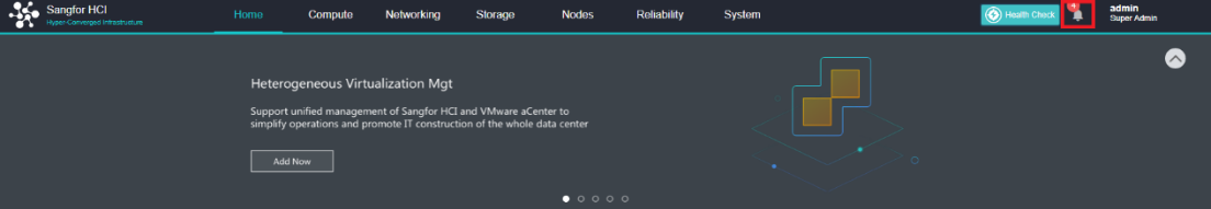
- On the Alerts interface, you can view the alert log severity, time, object type, alert object, event, description, and the number/total number of unacknowledged alerts. After discovering the alert information, deal with it in time and eliminate the alert information.
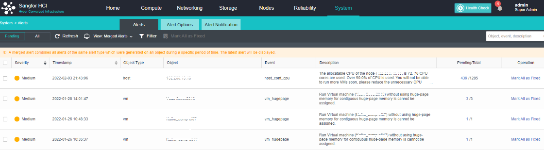
- On the Alert interface, you can also view all alerts, filter alerts, and search for alerts.
Healthcheck
Application Scenario
It is suitable for the operation, maintenance, and monitoring scenarios of the HCI platform. The administrator can manually perform a Healthcheck to diagnose the health status of the entire HCI platform. Facilitates fault location and resolution.
Precautions
- The Healthcheck detection check item will not check the Disk performance item by default because this detection will test the performance of the evaluation, which may affect the customer’s business storage performance. Manually check and detect when the business is idle.
- The entity type includes:
- Running Status
- Configuration
- Physical Resources
Steps
- Click on the Health Check page, select the items to be checked, and click Start.
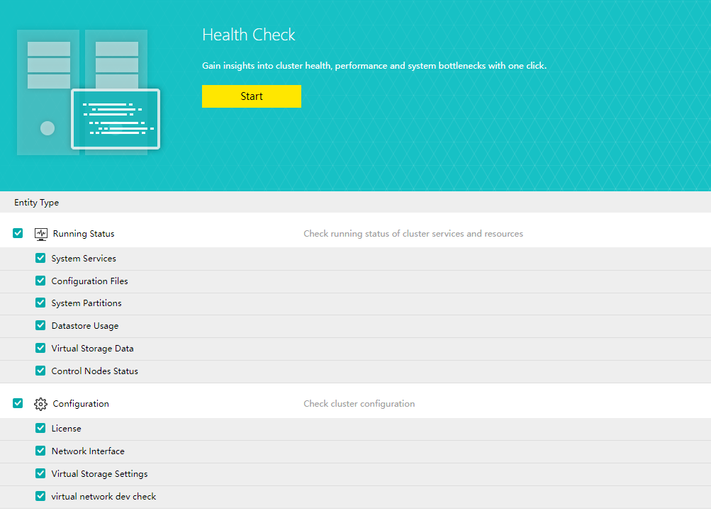
- There will be time-consuming and progress prompts during the detection process, and the detection can also be manually interrupted.
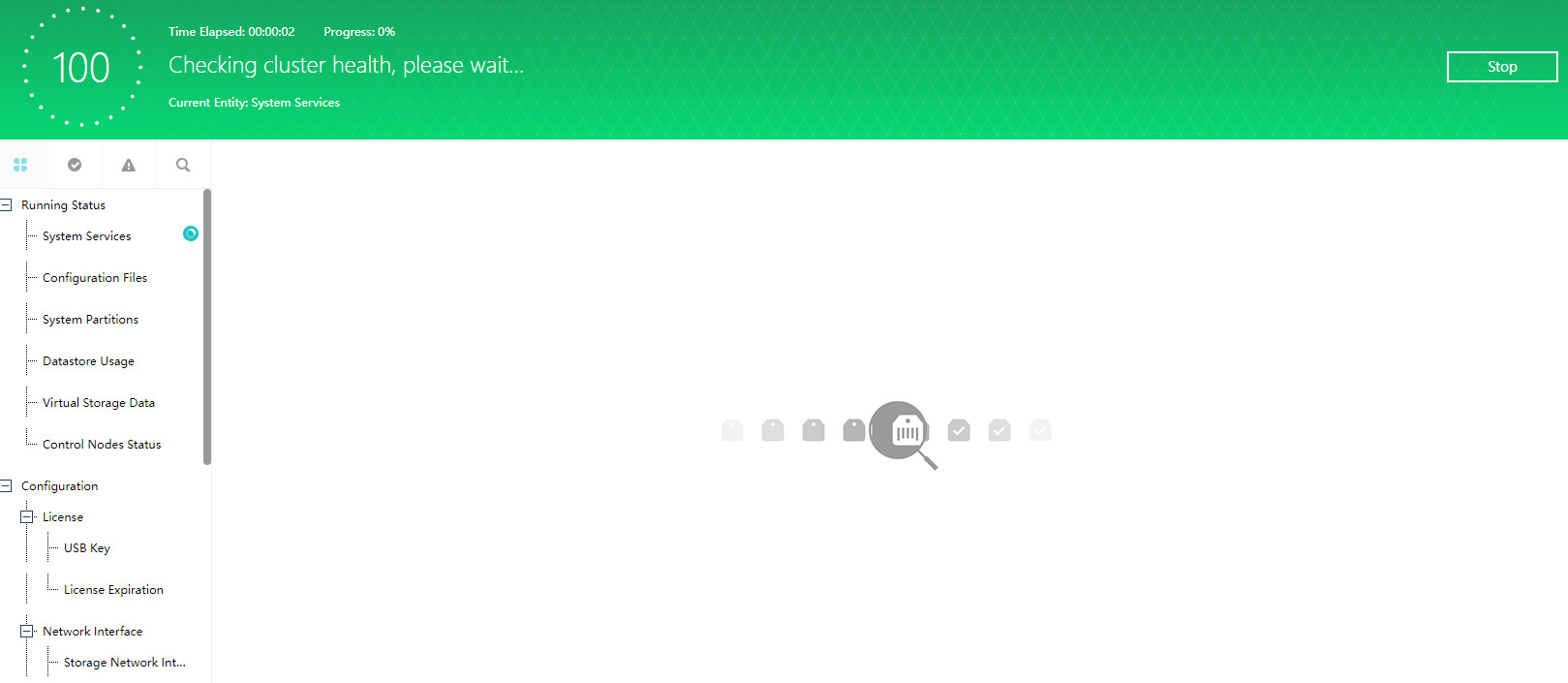
- After the detection, you can filter all entity types, normal entity types, and abnormal entity types in the upper left corner. You can also search for entity types, click the abnormal entity type, and it will prompt the abnormal situation detected by the current cluster. The corresponding solutions are given below.
aDeploy
Application Scenario
It is suitable for HCI delivery and after-sales operation and maintenance scenarios. The platform hardware status, operating status, early warning patch package detection, and other items are checked through tool inspection and suggested actions are given. Platform logs are provided in the toolbox of aDeploy tools collection, server IPMI information collection, and other tools to meet the daily troubleshooting needs of operation and maintenance personnel.
Precautions
When the inspection result is abnormal and an alert of  severity level occurs, it needs to be dealt with first. You can refer to the suggested actions for optimization.
Steps
-
Login to Sangfor Community (https://community.sangfor.com).
-
Go to Self Service > Download > Tools and click download on Sangfor HCI/SCP aDeploy.
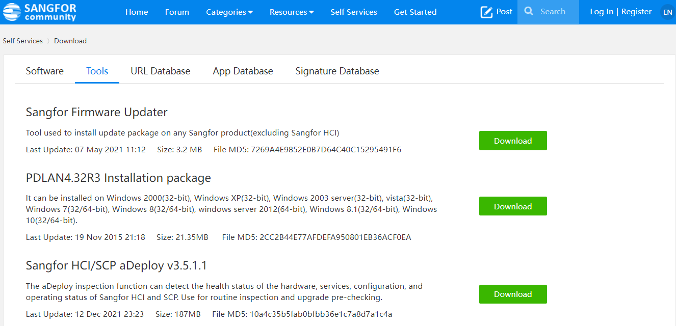
-
After downloading and decompressing, run the tool for inspection.
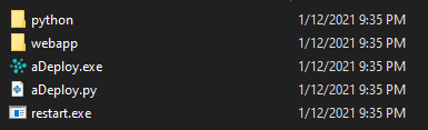
Troubleshooting Module
System Diagnostics
Application Scenario
Perform simple command-line operations through the web page, view basic information about the network and background, and simplify the troubleshooting process. The interface lists the commands supported by the HCI console and the functions of the commands.
Steps
-
Log in to the HCI console, navigate to System Management > System Maintenance > System Diagnostics, and click to enter the System Diagnostics page.
-
In Server, you can select the IP of the physical machine that needs to perform command operations.
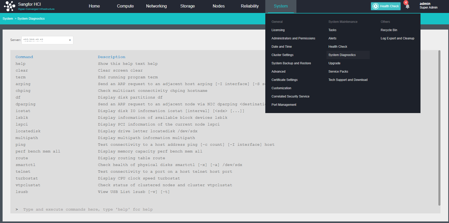
- The currently supported command and functions are listed in the interface. Enter and execute commands as needed.
Console Packet Capture
Application Scenario
It is convenient to capture packets from the node’s interface through the web page, and the captured data packets can be downloaded to the local for analysis.
Steps
- Log in to the HCI console, navigate to Networking > Topology page, select the device that needs to capture packets, and click Packet Capture.
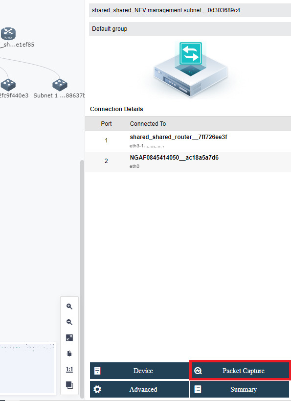
- Capture the data packets passing through the interface by specifying the virtual device’s interface and conditions.
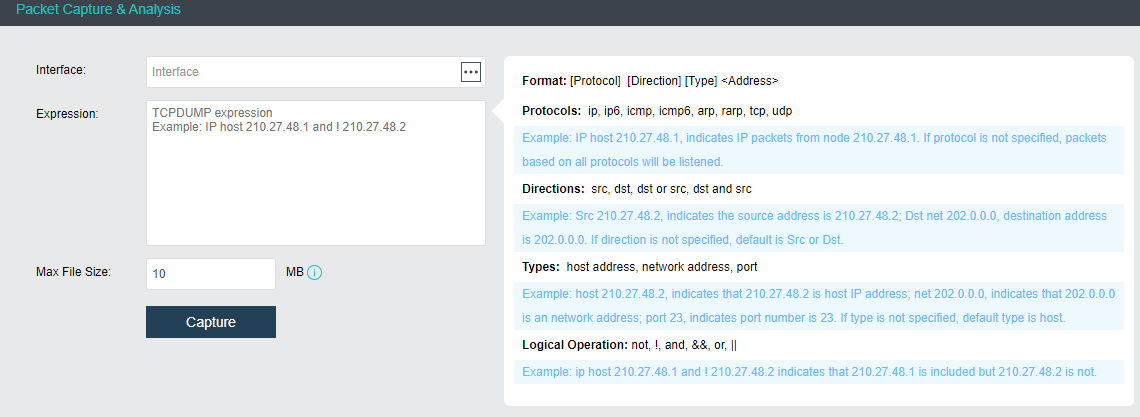
-
Designated interface: Select the network port corresponding to the device that needs to capture packets.
-
Condition: Configure the packet capture conditions. The conditional format supports Protocols, Direction, Type (address), and Logical Operation.
Test Connectivity
Description
Check the connectivity of virtual machines, troubleshoot the causes of network communication failures, and support ICMP, TCP, and UDP packet detection under IPv4/IPv6 protocols.
Precautions
- Connectivity detection does not support mutual access between IPv6 and IPv4.
- The virtual machine in the shutdown state or the virtual machine in the interface disabled state cannot be selected.
Prerequisites
- The virtual machine has the vmTools installed.
- Linux requires perl to be installed.
Steps
- Navigate to Network > Topology, and click Test Connectivity to enter the Test Connectivity page.
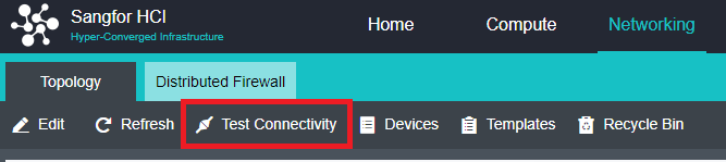
- Select the source VM and enter the destination IP.
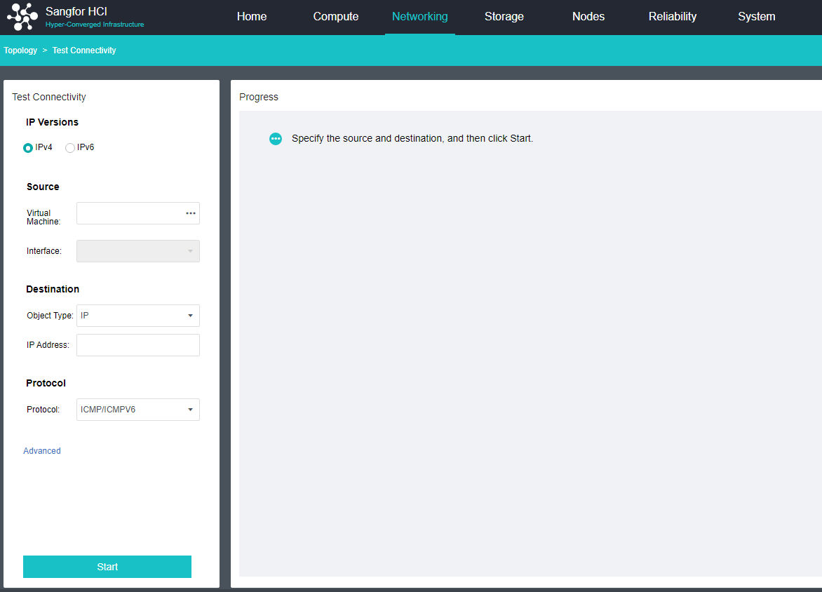
-
Click Start to test the network.
-
Example of successful network test.
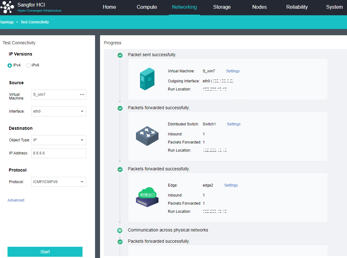
- Connectivity test failed example. The platform gives suggestions for failure.
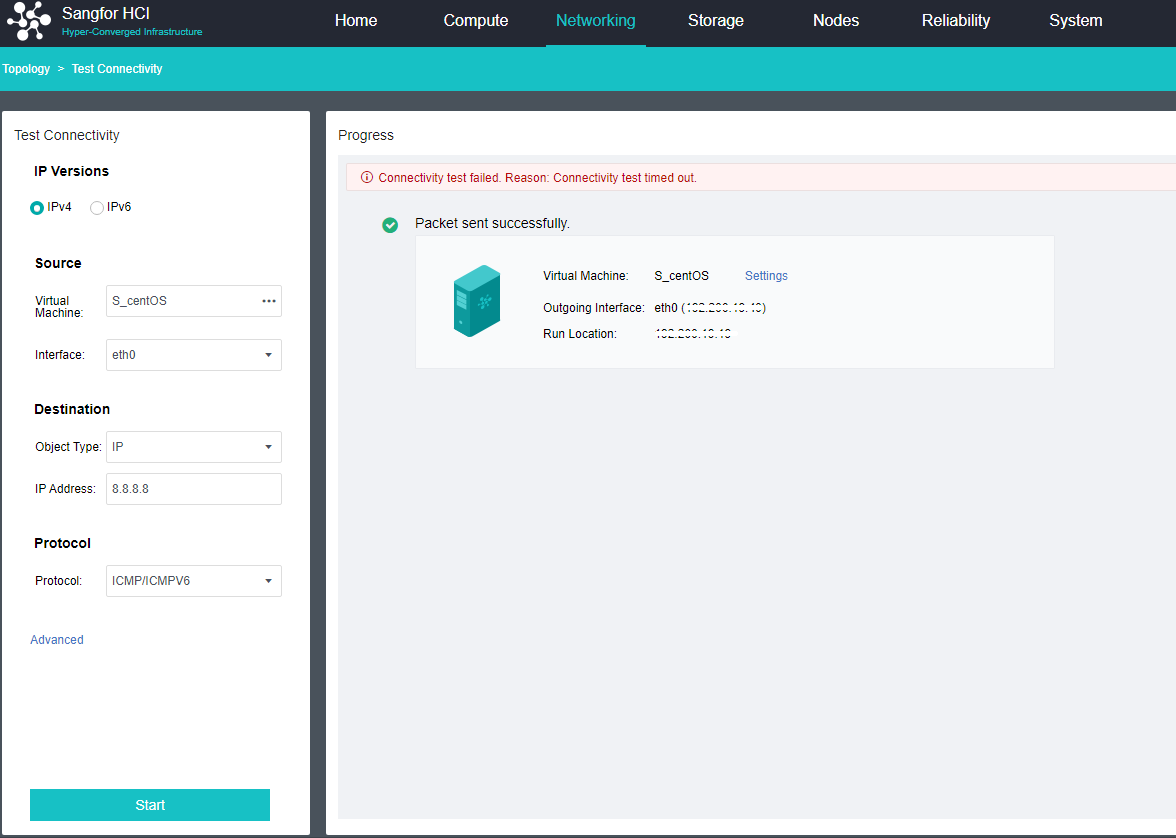
Port Management
Application Scenario
When the operation and maintenance personnel need to perform some operations, they need to open some ports. For example, when the operation and maintenance personnel need to perform node expansion, node replacement, and inspection, they need to open the SSH port. The specific ports and usage scenarios are as follows:
| Service Name | Port | Protocol | Description |
|---|---|---|---|
| New Host Discovery Service | 4099 | udp | Used to discover physical nodes with HCI installed. |
| Virtual Machine Migration Service | 7001-7019 | tcp | Used for intra-cluster and cross-cluster virtual machine migration. This port will be automatically enabled when the Sangfor Cloud Platform(SCP) manages the cluster. |
| p2v migration service | 4000-4010 10809-10900 |
tcp/udp | Used to process migration request tasks and migration data transfers when performing p2v tasks. |
| Samba service | 139,445 | tcp | Samba shared directory management service, providing file sharing functions. |
| API Services | 4433 | tcp | Used to provide API interface to third-party calls |
| SNMP service | 161 | udp | The SNMP service help administrators understand the usage of physical resources, which requires an independent account and password to use the service. |
| SSH port | 22 | tcp | It is used for host expansion, host replacement, and inspection to connect to the host. |
Steps
- Log in to the HCI console, and navigate to System > General > Port Management. On this page, you may Enable and Disable the cluster port.
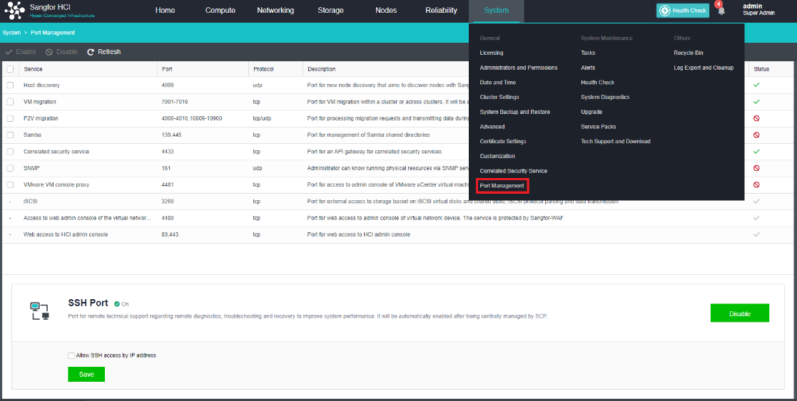
- On this page, you can enable and disable the SSH port at the same time. It is also possible to restrict the IP addresses that can access the SSH port by enabling SSH IP Restriction.
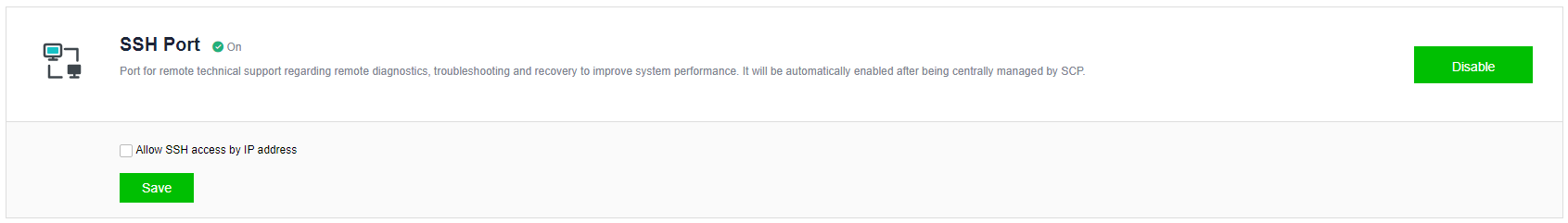
Platform Daily/Weekly/Monthly Operations and Maintenance
To standardize the daily operation and maintenance of the HCI platform, you can refer to the following steps in combination with the actual situation in the customer environment to establish a complete daily, weekly, and monthly operation and maintenance management process. It will ensure the stability of the working state of the entire platform in a systematic way.
Daily Maintenance
It is recommended to check the corresponding alert information on the HCI console for daily maintenance. You should immediately deal with emergency-level alerts. For ordinary-level alerts, you should formulate a processing plan. For specific maintenance recommendations, please refer to the following table:
| Maintenance Scope | Maintenance scenario | Maintenance advice | Operations |
|---|---|---|---|
| HCI status check | Monitor the hardware resources and components of the HCI node to quickly discover system abnormalities. | Check the status of the physical server if any physical host is offline. Whether the storage status is normal, the disk status is normal; |
|
| Node alert monitoring | Node swap partition usage is too high. | It is recommended to expand the node memory or shut down temporarily unused virtual machines. | |
| Node offline | It is recommended to check whether the node or network is abnormal and perform service recovery immediately. | ||
| The node system partition is abnormal | There may be bad sectors or failures in the system disk, please contact Sangfor technical support. | ||
| Node GPU usage is too high | Please shut down some virtual machines or migrate some virtual machines to other nodes. | ||
| The node cannot detect the graphics card | Please log in to IPMI to check whether the graphics card is abnormal | ||
| The graphic card temperature of the node is too high | Please check whether the heat dissipation of the node or the temperature of the server room is abnormal. | ||
| Multiple types of graphics card hardware detected | Please remove the heterogeneous graphics card. Otherwise, the GPU-Supported VM will not run on the node. | ||
| Insufficient memory on the node | Please shut down some virtual machines or migrate some virtual machines to other nodes. | ||
| Node CPU usage is too high | It is recommended to expand the capacity of the node or shut down the virtual machines that are not in use temporarily. | ||
| The node CPU temperature is abnormal | It is recommended to check whether the temperature of the equipment room, the node fan, and the cooling equipment is normal. | ||
| Host CPU throttling | If the server frequently drops alerts, you need to check whether the CPU hardware status is normal through the BMC. | ||
| Node memory usage is too high | It is recommended to expand the node memory or shut down temporarily unused virtual machines. | ||
| Node memory downclocking | It is recommended to log in to the node’s BMC console and check the node’s memory. | ||
| RAID card status is abnormal | The status of the RAID card is abnormal. Check whether the disk and storage status are normal. If it is not normal, please contact Sangfor Support in time. | ||
| The memory module (%s) of the node (%s) is faulty. | Please troubleshoot or replace the memory stick. | ||
| The SMS function is abnormal, and the connection between the SMS agent module and the sending module is abnormal. | Please check whether the SMS configuration is correct and the network connection is normal. | ||
| Memory over-provisioning alarm | Memory capacity expansion is recommended. | ||
| VCPU overcommitment alert | Node capacity expansion is recommended. | ||
| The speed of the interface is too low | It is recommended to replace the NIC or network cable. | ||
| Network alert monitoring | The node NIC is working abnormally. | If frequent alarms occur, it is recommended to replace the host NIC | |
| The network packet loss rate is too high | Check whether the physical network is abnormal | ||
| The node has a persistent packet loss error | Check whether the physical network is abnormal | ||
| The VXLAN ports of node xx and node xx are blocked | Check the configuration of the VXLAN port and the configuration of the VXLAN switch. | ||
| The interface of node xx is disconnected. | Please check the interface connection status of the node. | ||
| Virtual network device (%s) not responding | Check the status of virtual network devices | ||
| If node X cannot reach the gateway, please check whether the network connection is abnormal. | It is recommended to check whether the network is normal. | ||
| Storage Alarm Monitoring | Storage IO latency is too high | It is recommended to check whether the storage network is normal. | |
| Storage usage is too high | 1. Delete virtual machines that are no longer needed. 2. Clear junk files in the recycle bin. 3. Expand storage capacity | ||
| Storage disconnected from Node or Storage dropped. | Check storage and node network conditions in a timely manner. | ||
| Abnormal storage status | Check whether the storage is faulty in time | ||
| Node xx access to storage remains busy. | It is recommended to upgrade storage or migrate some virtual machines to run on other storage. | ||
| Bad disk state, remounted. | Log in to the BMC console of the server, check the hardware-related logs, and confirm the cause of the fault. | ||
| It is detected that there is data block reuse in the storage. Please contact technical support as soon as possible for assistance. | Contact Sangfor technical support for assistance | ||
| Hot spare replacement detected | Log in to the HCI web console to view the status of the replaced disk Log in to the BMC console of the server to view hardware-related logs. |
||
| It is detected that the hard disk (node <%s>, hard disk name: %s) has been pulled out. If it is ejected by mistake, please reinsert the hard disk back to the original disk as soon as possible! | Log in to the HCI web console to view the status of the disk. Log in to the BMC console of the server to view hardware-related logs. |
||
| Disk status is abnormal | Log in to the HCI web console to view the status of the disk. Log in to the BMC console of the server to view hardware-related logs. Attempt to plug and unplug the disk. |
||
| Disk bad sectors exceed the threshold. | Replace the disk as soon as possible | ||
| Disk IO error | Log in to the HCI web console to view the status of the disk. Log in to the BMC console of the server to view hardware-related logs. |
||
| Storage private network exception | Checking Storage Private Network Connectivity | ||
| License | License expiration reminder | It is recommended to purchase a new license in time. | |
| The license key status is abnormal. | It is suggested to unplug and plug the KEY. If it still does not work, contact Sangfor Support. | ||
| The licensed USB-KEY is pulled out. Please insert it. Otherwise, the system may be abnormal. | Check whether the USB-KEY is normal, and try to plug and unplug the USB-KEY. | ||
| Virtual Machine | Scheduled backup of virtual machine fails. | Check whether the backup repository is normal. | |
| The number of connection sessions is too high. The current session connection number is %s, which exceeds the threshold %s. %s | Check whether the service session of the virtual machine is normal, and try to adjust the session threshold. | ||
| The CPU usage of the virtual machine continues to be too high. | Check whether the vmTools of the virtual machine are normal. Try to scale the vCPU configuration of the virtual machine. |
||
| Corrupted virtual machine image file | Check whether the virtual machine can be started normally. If the virtual machine cannot be started, you can contact Sangfor technical support to solve it. | ||
| The virtual machine is out of memory. | Check whether the vmTools of the virtual machine are normal. Attempt to expand the memory configuration of the virtual machine. |
||
| The physical egress connected to the virtual machine does not bridge the node’s interface where the virtual machine is located, which will cause the virtual machine to fail to communicate with the external network. | Bridge the service incoming of the node to the physical egress. | ||
| The backup image of the virtual machine is found to be corrupted when deleting the backup. | If the virtual machine still exists, please back it up immediately and contact Sangfor technical support. | ||
| VM restart CDP fails | Please go to Administration > VM Backup and Recovery > Backup Policy page to manually enable CDP. | ||
| Failed to enable CDP on virtual machine | Navigate to Reliability > Scheduled Backup/CDP > HCI Backup Policies page to enable CDP manually. | ||
| The virtual machine is running, but its configured CDP policy is disabled, and the data is currently in an unprotected state. Please adjust the CDP policy | Please go to Administration > VM Backup and Recovery > Backup Policy page to manually enable CDP. | ||
| The virtual machine is not responding / virtual machine failed and has been automatically restarted and recovered. | Check the virtual machine log and check the reason for the no response of the virtual machine. | ||
| Persistent high GPU utilization of virtual machines. | Check virtual machine GPU load. Expanding virtual machine GPU configuration. |
||
| The virtual machine has insufficient video memory(VRAM). | Check virtual machine GPU load. Expanding virtual machine GPU configuration. |
||
| The packet loss rate of the network port is too high. | Check the virtual machine’s virtual NIC configuration. | ||
| The virtual machine’s IO log backup space exceeds the alert threshold. | Please adjust the backup space of the virtual machine IO log. | ||
| The detected operating system type of the virtual machine does not match the configuration, which may lead to inaccurate report information | Check whether the OS type of the virtual machine is the same as that configured in the HCI web console. |
Weekly Maintenance
Weekly maintenance tasks are mainly system configuration backup & detection, one-key inspection, and other tasks, and statistics of alert logs and fault handling for the week are also collected.
| maintenance scope | Maintenance scenario | Maintenance Description | Operations |
|---|---|---|---|
| UPS power check | When using UPS for power supply, it is necessary to manually check whether the UPS power is sufficient to prevent the risk of abnormal data recovery due to an abnormal power outage of the system. | Check whether the UPS has a sufficient power supply. If it is insufficient, power off the HCI system safely in time. | Refer to UPS battery instruction manual |
| System Configuration Backup Check | To ensure that backup data is available when the system is abnormal, it is necessary to check the availability of backup functions and data regularly. | Check whether the backup data exists according to the system backup. If there is any abnormality, please deal with it immediately. | Navigate to System > System Backup and Restore. |
| System configuration backup | To ensure that backup data is available when the system is completely abnormal, it is necessary to regularly back up the system configuration locally. | Backup system configuration to local. | Navigate to System > System Backup and Recovery, and click Backup to backup system configuration locally. |
| HCI system health check | Regularly conduct a comprehensive inspection of the HCI environment to prevent it from happening. | It is recommended to perform a health check on the system on HCI every week. If there are abnormal items, please deal with them immediately | Click Health Check on the home page. |
| Weekly alert handling | Weekly alert handling | Check the emergency alert on the current week and the execution of the common alert handling plan. |
Monthly Maintenance
Monthly Inspection
The aDeploy tool should be used to inspect the platform every month. The aDeploy inspection tool can perform in-depth inspections on the HCI platform. The specific inspection contents include:
- Platform hardware status detection
- Platform storage status detection
- Platform system key service detection
- Platform system configuration detection
- Platform network status detection
- Platform warning patch detection
- Platform security detection
After the inspection is completed, the entity type of the fault level should be processed immediately. The rectification plan should be formulated for the entity type of the alert level. The rectification should be completed gradually.
| maintenance scope | Maintenance scenario | Maintenance Description | Operations |
|---|---|---|---|
| Platform Health Check | Regularly conduct comprehensive inspections of the HCI platform to prevent problems before they occur. | HCI platform hardware status detection, platform running status monitoring, and detection. | Refer to the Detection with the aDeploy Tool section. |
Alert Patches
When a product problem is found, Sangfor will release a repair patch to minimize the product problem’s impact on the business.
After receiving the product warning and rectification announcement, the operation and maintenance personnel can use the aDeploy tool to inspect the current HCI platform to confirm whether the existing platform has any problems. At the same time, the operation and maintenance personnel should analyze the version information of the current platform and the actual situation of the services carried out on time, confirm the impact of the warning on the existing network platform and determine whether to perform patch repair operations according to the evaluation results. And determine whether to perform patch repair operations according to the evaluation results.
Availability Management
Platform availability management mainly ensures business continuity by checking the platform’s CPU, memory, storage, and other resources.
Pay attention to the CPU usage of the HCI platform. Consider expanding the capacity of the HCI platform in any of the following situations:
-
The continuous usage of the CPU exceeds 70%
-
In a common cluster scenario, the redundancy of CPU resources is insufficient to support the business system’s normal operation when one or two (two-copy, three-copy) nodes are damaged.
-
In the stretched cluster scenario, the redundancy of CPU resources is insufficient to support the business system’s normal operation when a node in a fault domain is damaged.
Pay attention to the memory configuration and memory usage of the HCI platform. Consider expanding the capacity of the HCI platform in any of the following situations:
- Sustained memory usage exceeds 80%
- The redundancy of memory resources in common cluster scenarios is insufficient to support the business system’s normal operation when one or two (two-copy, three-copy) nodes are damaged.
- In the stretched cluster scenario, the redundancy of memory resources is insufficient to support the business system’s normal operation when a node in a fault domain is damaged.
Pay attention to the storage capacity utilization rate of the HCI platform, and consider expanding the storage capacity in any of the following situations:
-
Storage usage exceeds 90%
-
The administrator can predict the number of days that the remaining storage capacity of the HCI Platform can support the use of the business system through the usage trend of storage capacity and adjust the expansion plan according to the forecast data. When the predicted remaining storage capacity is not enough to support the business system for 90 days, it is necessary to consider expanding the storage resources of the HCI platform.
Pay attention to the storage performance of the HCI platform, and evaluate whether the current HCI platform’s storage performance can meet the business system’s needs by analyzing the IOPS of important virtual machines. When the IO latency of the business system is greater than 20ms, the storage performance of the HCI platform needs to be expanded.
Pay attention to the HCI platform’s business system backup and disaster recovery implementation. If necessary, you can select some business systems to perform recovery drills to ensure that the business systems’ backup and disaster recovery data are normal. In extreme cases, they can be restored through backup or disaster recovery data business.
The specific indicators of concern refer to the following table:
| Maintenance Project | Concerns | Maintenance Description |
|---|---|---|
| CPU usage | CPU continuous usage does not exceed 70% | View the peak usage and continuous usage of the CPU in the last month |
| CPU resource redundancy | In a common cluster scenario, the redundancy of CPU resources is insufficient to support the business system’s normal operation when one or two (two-copy, three-copy) nodes are damaged. In the stretched cluster scenario, the redundancy of CPU resources is insufficient to support the business system’s normal operation when a fault domain node is damaged. |
Calculate whether the redundancy of the current CPU resources meets the requirements |
| Memory usage | Sustained memory usage does not exceed 80% | View the peak usage and sustained usage of memory in the last month |
| Redundancy of memory resource | In common cluster scenarios, the redundancy of memory resources is insufficient to support the business system’s normal operation when one or two (two-copy, three-copy) nodes are damaged. In the stretched cluster scenario, the redundancy of memory resources is insufficient to support the business system’s normal operation when a fault domain node is damaged. |
Calculate whether the redundancy of the current memory resources can meet the requirements |
| Storage usage | The storage utilization rate does not exceed 90%, and the predicted remaining storage capacity is sufficient to support the business system for more than 90 days. | View current storage resource usage and forecast capacity usage after 90 days |
| Business backup or disaster recovery | Business backup and disaster recovery tasks are performed normally. Back to normal |
Check the execution status of business backup and disaster recovery tasks Conduct business recovery drills |
Security Management
The security of the HCI platform is very important, and the security of the HCI platform should be checked monthly, including the following items:
| Maintenance Project | Maintenance scenario | Maintenance Description | Operations |
|---|---|---|---|
| Scope of allowed login | Check the configuration of the current platform user’s allowed login scope | Check whether the current platform user has enabled the restriction of allowed login. | Navigate to System > Administrators and Permissions > Login & Password Policy. |
| Password validity period | Check the configuration of the current password validity period | Check if the current password is valid for six months or less | Navigate to System > Administrators and Permissions > Login & Password Policy. |
| Number of wrong passwords entries. | Check the configuration for the number of incorrect password entries. | Check whether the Max Password Retry Attempts are within 10 entries. | Navigate to System > Administrators and Permissions > Login & Password Policy. |
| Port management | Check the enabled ports of the platform. | Check if the platform has ports that are not in use, and disable ports that are not currently in use. | Navigate to System > Port Management. |
| Patch service connectivity detection. | Check patch server connectivity. | Check the connectivity of the patch service to ensure that the patch service is connected correctly. | Navigate to System > Service Maintenance > Service Packs > Settings. |
Basic Business Change
Powering On and Off the System
Powering On and Off a Single Node
Scenario
The administrator can use the maintenance mode when the administrator needs to power off a single node in the hardware maintenance scenario. After the maintenance mode is activated, the system will first migrate the services on the platform to other nodes to ensure that the replacement process will not affect the business.
Precautions
- The cluster controller does not support the Enter Maintenance Mode. If you need to maintain the cluster controller, please switch to other nodes as the master first.
- If there are nodes offline in the environment, you cannot enter the maintenance mode.
- There is a task in progress on the node to be maintained. You cannot enter the maintenance mode temporarily. You need to wait for the task to complete before entering.
- Currently, only one node is allowed to enter maintenance mode at the same time.
Prerequisites
None.
Steps
- In Node, click More and choose Enter Maintenance Mode.
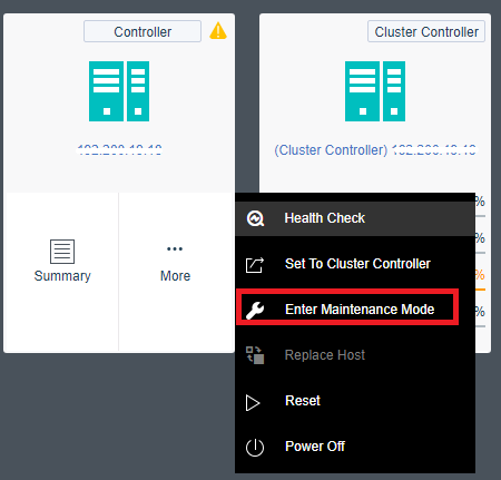
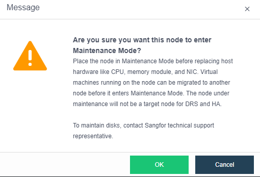
- After entering the password, select OK to enter the node maintenance mode. The system will isolate the node. In this step, you can also check the After entering maintenance mode, the node will automatically shut down checkbox.
- The node enters maintenance mode successfully. You can click Power Off on the web console to power off the node.
- After maintenance is complete, power on the server and wait for it to fully start, then exit the maintenance mode.
- After the virtual storage data is synchronized, the virtual machines on other nodes can be migrated to this node to run.
Powering On and Off the HCI Cluster
Scenario
When the server room is undergoing routine maintenance (routine power outage) or relocation, it is necessary to power off and power on the HCI cluster. To fully guarantee the service system’s availability and avoid the power-off process’s impact on the user’s service data. You should manually shut down business services before powering off, shut down the virtual machine, and finally shut down the HCI cluster.
Precautions
- Before powering off the HCI cluster, ensure that no other tasks are being executed in the entire cluster.
- The virtual machine’s shutdown operation should use the HCI web console’s shutdown function or the virtual machine’s shutdown function. It is forbidden to use the power-off function of the HCI web console.
- The shutdown operation of the server should be performed on the node page of the HCI web console. It is forbidden to directly unplug the power supply or press and hold the server shutdown button to perform the shutdown operation.
- The cluster power-off process should follow the sequence of shutting down services first, then shutting down virtual machines, then servers, and finally network devices.
- The cluster power-on process should follow the sequence of turning on network devices, turning on servers, turning on virtual machines, and finally turning on business services.
Steps
Cluster power-off process
-
Log in to the HCI web console and check whether any tasks are being executed in the task list of the HCI platform. If a task is being executed, wait for the task to finish running before continuing the operation.

-
Manually shut down the service of the business system (optional)
-
On the Compute > Sangfor HCI page, select all virtual machines, select the shutdown operation, and ensure that all virtual machines are powered off.
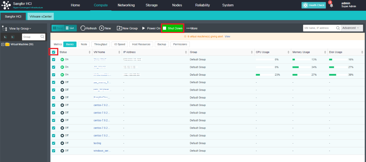
-
Navigate the Networking > Topology, and click Devices to enter the device list page.
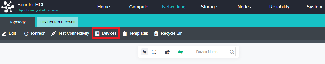
- Select all devices and click Shut Down to shut down the virtual network device.
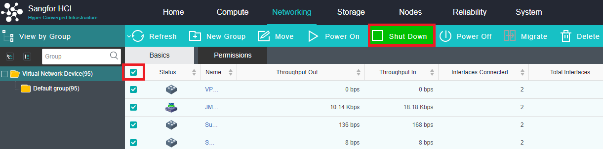
- After the shutdown is completed, you can use the method in step 1 to check whether tasks are being executed in the task list.
- Open the Nodes page, select the non-cluster controller nodes one by one, and click More > Power Off to perform the shutdown operation. Finally, select the cluster controller and click More > Power Off to perform the shutdown operation.
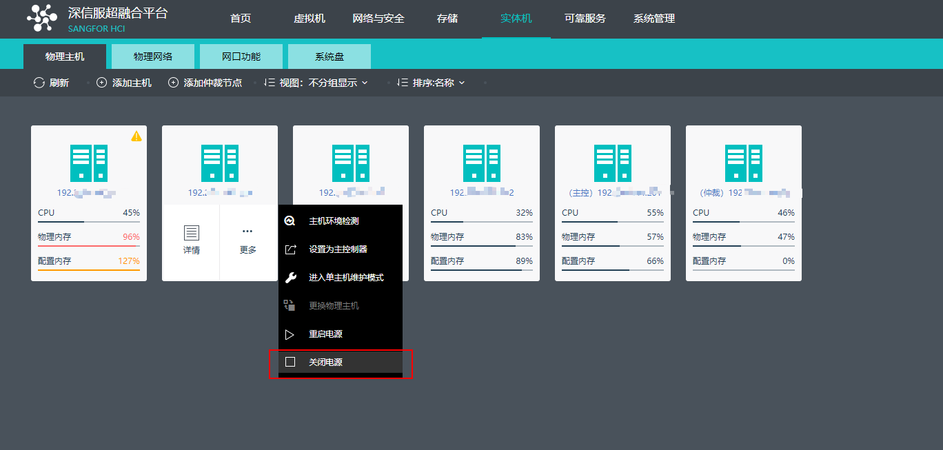
- After confirming that the server is shut down, shut down the associated network devices.
Cluster power-on process
-
Power on the network device and perform a network test to ensure the network is normal.
-
Power up the server and ensure that all power to the server is functioning properly.
-
After the server starts normally, wait for 10-20 minutes, log in to the HCI console, and perform Health Check on the home page to ensure that the Health Check score is 100 points.
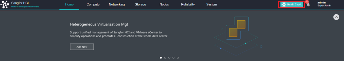
-
Check whether tasks are being executed in the task list of the HCI platform. If there are tasks to be executed, you need to wait for the tasks to be executed before continuing.

-
Navigate the Networking > Topology, and click Devices to enter the device list page.

- Select all devices and click Power On to start the virtual network device.
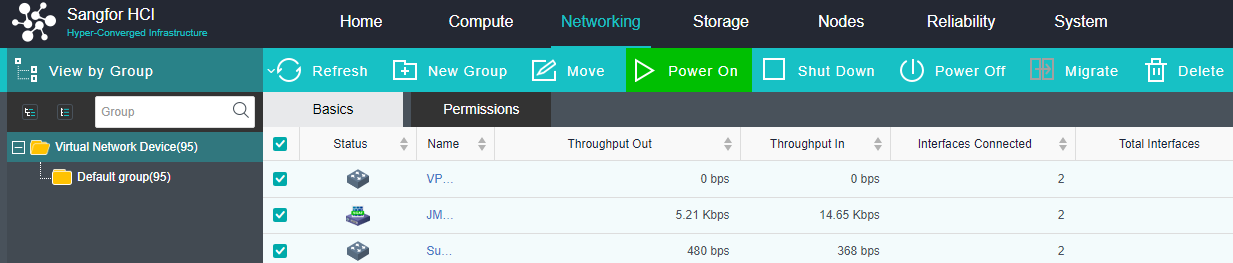
- On the Virtual Machine page, start the virtual machine step by step, and enable the services of the production system on the virtual machine. The power on and enabling services should follow the sequence of powering on the database virtual machine first and then powering on the application virtual machine after the database service is normal.
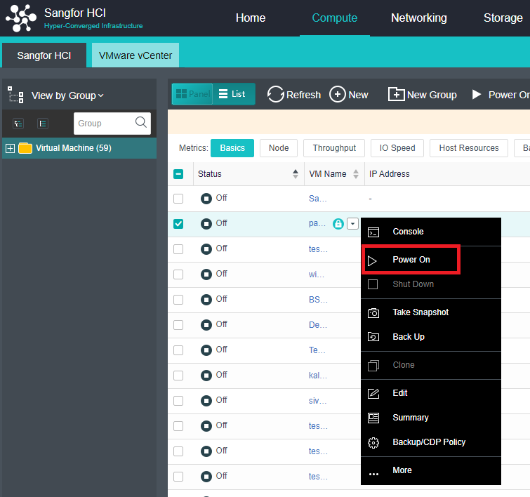
- During the startup process, verify whether the business system is normal one by one. After the current business system is normal, start other business systems.
Platform Version and Patch Package Upgrade
For the upgrade guide, please refer to Sangfor HCI&SCP Upgrade Solution.
HCI Platform Network Settings and Changes
When the user’s network planning changes, it involves the network configuration changes related to the HCI platform. The HCI platform is divided into four network planes: management network, private storage network, VXLAN network, and service network.
Virtual Network Setup and Operation
Refer to Chapter 6 Configuring Virtual Network.
Virtual Storage Setup and Operation
Refer to Chapter 3.6 Virtual Storage Configuration Guide.
Expansion Changes
Node Expansion
Description
When the cluster resources are in short supply, the resources can be expanded.
Precautions
- Node expansion will trigger data balancing. It is recommended to perform operations during non-business hours.
- If it is a two-node cluster, you need to shut down all virtual machines and NFV devices in the cluster when expanding to a three-node cluster.
- If the number of clustered nodes is greater than or equal to 3 and if the node is expanded at this time, it is necessary to stop the business.
- Ensure that the authorization of the expanded platform is sufficient.
- If the message “The current cluster’s licensing is the enterprise version. It is not supported to add test devices to the cluster. Please contact Sangfor customer service if necessary.” prompt when a cluster is added. In this case, the current node does not have the signature of the test device, and the node to be added was signed, which caused the two devices to be inconsistent. Solution: Contact Sangfor technical support to sign the device that the test device has not signed, and then re-scan the code to apply for the Licensing.
Prerequisites
- Plan the IP addresses of each network plane of the expansion node.
- The aSV software has been installed on the expansion node and is the same as the original version (including patches), and the management IP has been set.
- The management interface, overlay network interface, service port, and storage port of the expansion node have been correctly connected to the network.
Steps
- Click Add New Node in Nodes.
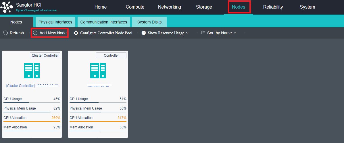
-
Select the node to be added. If the node to be added is not in the list, click + to add it. When prompted that the firewall configuration will be cleared, click OK.
-
If the prompt that the MTUs of the overlay network interface between the nodes are inconsistent, click Configure Now and check Enable interface high-performance mode checkbox. The overlay network interface and the incoming interface can be adjusted according to the actual network environment.
-
Navigate to Storage > Virtual Storage, and click Expand Capacity.

-
According to the actual network, select the virtual storage communication network deployment mode.
-
Select the appropriate storage network port and configure the IP.
-
Click Expand Capacity again to select the virtual datastore that needs to be expanded by the node.
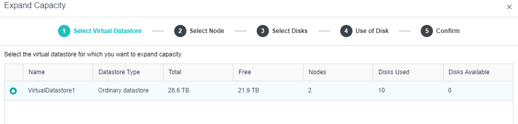
- For disk configuration, it is recommended to use SSD as the cache disk and HDD as the data disk and spare disk.
Note:
When the HDD is set as a spare disk in version 5.8.7R1, the HDD must be removed from the hard disk group first and then set as a spare disk.
-
Enter the name of the virtual datastore to be expanded and the administrator password of the admin to confirm the configuration.
-
After the expansion, perform Healthcheck to confirm that the cluster is running normally.
Hard Disk Expand Capacity
Description
When the virtual datastore capacity is insufficient, and the HCI node has free disk slots, the storage volume can be expanded by adding disks.
Precautions
- After replacing the disk, data rebuilding and balance are involved, which will affect the business. It is recommended to operate when the business is idle.
- If the RAID card of the aServer device is in JBOD mode, the disk supports hot swapping, and the disk can be inserted without shutting down the server.
- If the RAID card of the aServer device is in RAID 0 mode, the disk does not support hot-swapping, so you need to power off the server and then insert a new disk. Set the single disk to RAID 0 for the new disk, and then perform expansion.
- After expansion, the following conditions must be met:
- The total capacity of data disks between nodes, the highest and lowest difference, cannot exceed 50%.
- The total number of data disks between nodes and the difference between the maximum and minimum data disks cannot exceed 3.
- The ratio of the cache disk capacity to the data disk capacity of each node cannot be less than 5%, and the difference between the ratios between nodes cannot exceed 5%.
- The ratio of the number of cache disks to mechanical disks in each node is greater than or equal to 1:6.
- In the case of two nodes, the capacity must be the same.
- If the cache disk is added separately, you need to contact Sangfor technical support for the operation after adding it to the interface.
Prerequisites
- The new disk has been inserted into the node and can be recognized by the platform.
- Ensure that no tasks are running on the Task Execution page of the virtual storage.
Steps
- Navigate to Storage > Virtual Storage, and click Expand Capacity.
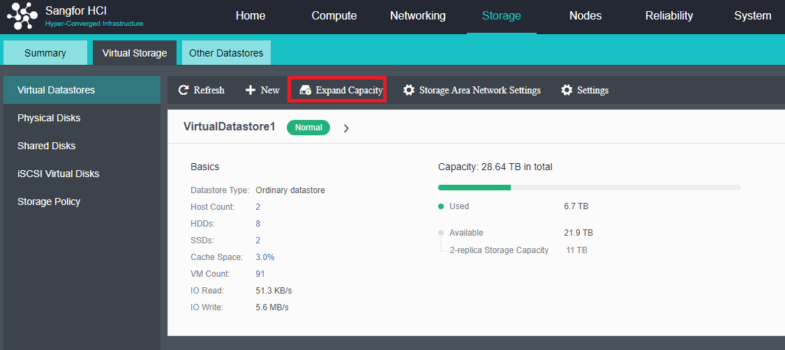
-
Select Expand Capacity, enter the configuration disk, and select the purpose of the newly discovered disk: data disk, cache disk, spare disk, and not added to the virtual storage.
-
After confirming the configuration, please enter the name of the virtual datastore to be expanded and the administrator password of admin, and click OK.
-
After the disk is expanded, perform a health check to confirm that the platform runs stably.
Platform Hardware Maintenance
Hardware Inspection
Regularly inspecting the hardware of the HCI platform with aDeploy, an intelligent used for detecting the hardware risks of the HCI platform in advance and dealing with them in time, is a key measure to ensure the stability of the HCI platform and business.
aDeploy intelligent delivery tools have comprehensively covered hardware-related problems and risks. The inspection contents for hardware are as follows:
| No. | Inspection items |
|---|---|
| 1 | Node online detection |
| 2 | Node CPU detection |
| 3 | Node memory detection |
| 4 | Node network port detection |
| 5 | Platform mechanical disk health check |
| 6 | Platform SSD Health Check |
| 7 | System disk detection |
| 8 | RAID Card Health Status Detection |
| 9 | RAID card compatibility detection |
| 10 | Cluster resource usage detection |
| 11 | VXLAN interface high-performance mode detection |
| 12 | Disk SMART information detection |
| 13 | Platform IMPI detection |
| 14 | System abnormal restart detection |
Hardware Alert
Regularly check the status of the indicators on the server panel and the logs on the IMPI management interface to monitor the running status of the server hardware from the node level.
Panel Indicator Lights
- Sample panel indicator and hard disk status indicator
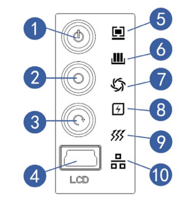

| No. | Module name | Normal condition | Abnormal condition |
|---|---|---|---|
| 1 | Server switch button | NA | NA |
| 2 | ID light and button | NA | NA |
| 3 | Reset key | NA | NA |
| 4 | LCD liquid crystal management module interface | NA | NA |
| 5 | System fault indicator | No light | When a fault occurs, it is always red |
| 6 | Memory fault indicator | No light | Flashes red when a warning occurs |
| 7 | Fan fault indicator | No light | When a fault occurs, it is always red |
| 8 | Power failure indicator | No light | Flashes red when a warning occurs |
| 9 | System overheat indicator | No light | When a fault occurs, it is always red |
| 10 | Network status indicator (eth0 eth1) | plug-in cable | – |
| 11 | Hard drive activity indicator | green | NA |
| 12 | Hard disk failure alarm indicator | Blinking green: Hard disk read and write activity. | Steady red: Hard disk failure Steady blue: hard disk location Steady purple: with RAID Rebuilding |
IPMI Information
When an abnormality occurs in the panel indicators, it is necessary to determine the problem further. To locate the problem, you need to view the detailed event log through IPMI. The daily handling methods are as follows:
- Suggested solutions for the power outage.
- Access IPMI to view the event logs to confirm whether the CPU is overheating or the memory is overheating.
- Check the heat-generating parts; the momentary heat is usually caused by ambient temperature and will recover automatically. However, if it continues to overheat, it must be turned off for further inspection.
- If It continues to overheat and cool down by itself. You need to contact experts to confirm whether to repair it.
- Suggested solutions for memory failures
- Access IPMI to view the event log to confirm the specific slot of the abnormal memory module.
- Fault type, for example, the memory device is disabled, and the slot is unable to identify the capacity. Try to plug and unplug the RAM. If still unable to solve, proceed to RMA(Return merchandise authorization). If the ECC cannot be fixed, directly RMA the corresponding memory.
- For alerts, the number of (correctable ECC) is usually small and is not reported continuously for several days. You can clear the log and restart the BMC to solve the problem; if the number of continuous reports is large, repair the corresponding memory.
- Suggested solutions for fan failures
- Access IPMI to view event logs and view sensor values.
- When the fan speed value is higher or lower than the BMC set threshold, an alert will be issued, which usually can be recovered by itself and does not occur repeatedly, so don’t ignore it.
- The fan is faulty, and the sensor shows an abnormal fan value. If still unable to fix it after plugging and unplugging the fan, request RMA directly.
- Suggested solutions for system failures
- Access IPMI to view the event log (usually subsystem health failure).
- Gather the IPMI event log to confirm whether the system is abnormal. A restart can usually solve the system’s abnormality.
- You need to contact a specialist to confirm whether to request RMA if restarting cannot solve the issue.
- Suggested solutions for hard disk failures
- Re-plug the raid card.
- Confirm whether the raid card is recognized in the BIOS.
- Confirm whether there is a hard disk on the raid card.
- Request RMA if plugging and unplugging the JBOD disk couldn’t solve the issue.
Server Disassembly Specifications
Anti-static treatment
When the weather is dry, the human body rubs against the clothes, which easily generates static electricity. This static electricity may cause damage to the chips on the integrated circuit. Therefore, it is necessary to discharge the static electricity on the human body when directly contacting the circuit board or related boards. Before touching the device, you should wear anti-static work clothes, anti-static gloves, or anti-static wrist straps, and remove easily conductive objects (such as jewelry, watches, etc.) on your body, as shown in the figure, to avoid electric shock or burns.

The method of wearing an anti-static wrist strap is shown in the figure.
- Insert your hand into the anti-static wrist strap.
- Tighten the buckle to confirm that the anti-static wrist strap is in good contact with the skin.
- Insert the ground end of the ESD wrist strap into the ESD wrist strap jack on the cabinet or chassis (grounded).

Protection against liquid splashes on the circuit board
If there is liquid on the circuit board, it is easy to cause short circuits and corrosion of the circuit board. During operation, avoid liquid splashing into the circuit board. So, the requirements are as follows:
- Try to avoid liquid in the operating range. If there is liquid, cover the circuit board properly and do not place it near the liquid.
- When the ambient temperature is high, paying attention to the human body is necessary to avoid dripping sweat onto the board.
No violent disassembly
Usually, the assembly or disassembly of components is nicely designed. Please follow the instructions for assembly or disassembly. If it is found that a certain part cannot be installed in the pre-installation position or can’t be removed, there are usually structural control parts. Pay attention to the priority of disassembly and assembly, and do not disassemble and assemble the parts violently. Recommended:
- Strictly follow the product operating instructions.
- You can consult someone with experience in disassembly and assembly.
- Special attention should be paid to the use of tools, and the circuit board should not be scratched due to inattentiveness.
Avoid falling debris
Usually, electronic components are relatively fragile. Be careful not to drop heavy objects and hit the circuit board during operation. There is a high probability of component damage, and verify that no small component falls on the main board. These small parts may also cause short circuits when powered on, so be careful of foreign objects falling. Usually recommended:
- Disassemble the equipment and place it on a workbench or desktop for operation.
- The parts must be held firmly and prevented from falling during disassembly and assembly.
- Small accessories such as screws should be placed outside the equipment.
- Arrange the wiring after installation, and confirm that no debris is left inside the device.
Power off operation
The components involved in the operation on the motherboard, such as memory, CPU, PCIe expansion card, etc., must be powered off, not only shut down but also need to unplug the power cord. Individual components, such as hot-swappable hard disks, redundant modules, etc., can be directly replaced while the device is working.
Hardware Troubleshooting
Node Replacement
Description
When a node in the cluster goes offline due to a physical failure, it needs to be replaced with a new node.
Precautions
- Node replacement will trigger data rebuilding, which will occupy IO. It is recommended to consult with customers and operate during non-production hours.
- It is required that the CPU frequency, memory size and frequency, and hard disk capacity of the new node should not be lower than those of the original faulty node.
- If the number of hard disks of the new node is larger than that of the original faulty node, the capacity must be expanded after the node is replaced.
- It is recommended that the capacity of a single disk of the new node be the same as that of the original failed node.
- The new node’s management IP address cannot be the same as the original faulty node.
Prerequisites
- The IP addresses of each network plane of the new node have been planned.
- The aSV software has been installed on the new node and is consistent with the original version (including patches), and the management IP has been set.
- The management interface, VXLAN port, overlay network interface, and storage port of the new node have been correctly connected to the network.
Steps
- Find the faulty node in Nodes and click Replace Host.
- Confirm that the configuration of the new node is not lower than the original faulty node, and after installing the aSV software correctly, check the I am ready checkbox and click Next.
- Select the newly discovered node, click Next, and replace the node after adding it to the cluster.
- Configure the network, select the storage communication port, and configure the communication network port IP.
- Confirm the configuration: choose whether to refer to the disk configuration mode of the old host, check I am sure I want to replace the physical host, and click Finish.
- When the detection is passed, click Confirm, you can see the progress of the host replacement in the task center and wait for the host replacement to complete.
- After the data rebuilding is completed, perform a Health check to confirm that the platform is running.
System Disk Replacement
Description
If the system disk fails and the node is offline, or the system disk is detected as a sub-healthy disk, you can safely replace the system disk.
Precautions
-
If the system disk that does not support the RAID group is used to replace the disk, please contact Sangfor technical support.
-
Replacement of the system disk on multiple nodes simultaneously is not supported.
-
Not allowed to replace the system disk when there are tasks in the cluster.
-
Replace the main controller system disk is not supported. If you need to replace it, you need to switch the main controller to another node before replacing it.
-
The quorum node does not support the system disk replacement function.
-
Before and after replacing the system disk, it is forbidden to change the physical NIC.
-
After the system disk is replaced successfully, the maintenance mode will not be exited immediately. You need to wait for 1 minute for the node service to restart before exiting the maintenance mode manually.
-
If the system disk has insufficient space, the system disk configuration backup will fail.
-
Before replacing the system disk, you need to enter the single-node maintenance mode. Do not check After entering the maintenance mode, the node will shut down automatically checkbox.
-
The system will automatically back up the system disk data to other nodes every day and support the replacement of the system disk when the node is offline due to system disk failure.
Prerequisites
None.
Steps
-
Find the corresponding node in Nodes > System Disks.
-
Click Replace System Disk to enter maintenance mode.
-
When entering the maintenance mode, do not check After entering the maintenance mode, the node will shut down automatically. The shutdown will cause the node system disk data not to back up.
-
To enable maintenance mode, you need to migrate or shut down the virtual machines and virtual devices running on the node.
-
After confirming the virtual machine’s processing, click Next, and you will be prompted to enter the administrator password.
-
The node enters the maintenance mode, and the prompt is not applicable to the system disk to form a RAID scenario.
-
Click Confirm Replacement to enter the system backup interface.
-
Click Start Backup to back up the system disk configuration information of the node that needs to be replaced with another node.
-
After the backup is complete, the interface will display the instructions for replacing the system disk.
-
After removing the original system disk, insert the new system disk. Start the physical node through the installation CD/U disk of the same version and choose to replace the system disk. Then, enter the new system disk installation wizard, and choose to replace the system disk.
-
Enter the configuration network interface page, and write the node’s IP to be restored in the local node’s IP.
-
The system will automatically obtain the latest system disk data backup based on the entered IP for recovery.
-
Wait for the recovery to complete and prompts the node to restart.
-
After manually replacing the system disk, click Finish and wait for one minute and exit the maintenance mode.
Disk Replacement
Description
When a node in the cluster has a disk failure, it needs to be replaced with a new disk. (Supports data disk, cache disk replacement).
Precautions
- After the disk is replaced, data rebuilding will be triggered, affecting the business. It is recommended to operate when the business is idle.
- If the RAID of the aServer is in JBOD mode, the disk supports hot swapping, and it is possible to unplug the faulty disk and insert a new disk without shutting down the server.
- If the RAID card of the aServer device is in RAID 0 mode, the disk does not support hot-swapping, and the server needs to be powered off and then replaced. Set the single disk to RAID 0 for the new disk and perform the front-end operation.
- After the disk of the aServer machine fails, you must purchase a Sangfor disk before replacing the disk. Non-Sangfor disk virtual storage cannot be recognized.
- The location of the new disk must be on the same node as the failed disk. It is recommended to use the original disk.
- For aCloud 5.8.6 and earlier versions, you need to contact Sangfor technical assistance to refresh the cached data before running the cache disk.
Prerequisites
- The capacity of the new disk should be the same as the size of the failed disk (it is strictly forbidden to replace the disk with a capacity smaller than the capacity of the failed disk).
- Ensure that no tasks are running on the Task Execution page of the virtual storage.
Steps
-
Find the faulty disk in Storage > Virtual Storage > Physical Disks, select the faulty disk, and click Replace Disk.
-
Unplug the failed disk first, insert the new disk, and check the I’m ready checkbox.
-
Select the new disk and click Next.
-
Confirm the information about the new disk and the faulty disk, check the I’m sure I want to replace the disk checkbox, and click Finish, and then the platform starts to replace the disk.
-
After the replacement is complete, you can see no offline disks on the physical disk interface.
-
After the replacement is completed, perform Health Check to confirm that the platform is running stably.
Memory Replacement
Description
- When the memory of a node in the cluster is faulty, you can manually replace the faulty memory.
- When the memory resources in the cluster are insufficient, you can manually expand the memory capacity of the nodes in the cluster.
- For non-aServer computers, you need to contact the server vendor for operation and maintenance by the personnel of the corresponding vendor. Direct operation by Sangfor employees is prohibited.
Precautions
- The capacity can be expanded without stopping the customer’s business. The capacity expansion needs to be shut down one by one. It is recommended to carry out the business during off-peak hours.
- Before expanding the capacity, ensure that no task is running(data rebuilding, data synchronization, and data balancing) on the cluster.
- After each expansion of a node, wait for the virtual storage task to complete before expanding the capacity of the next node.
- Please strictly follow the operation plan provided by the server vendor when unpacking the hardware.
Prerequisites
- Confirm the vendor and model of the memory to ensure hardware compatibility. When the memory is expanded or replaced, it must be stored as Sangfor memory, and the parameters are the same as those on the original machine. The company prohibits third-party accessories.
- Confirm that the cluster’s current virtual storage task has no task running.
Steps
- Click Storage > Summary to check whether other tasks are being executed in the current virtual storage. If tasks are being executed, please wait for the tasks to be completed before performing maintenance operations.
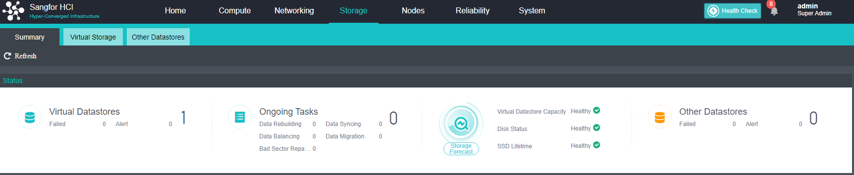
- Enable Enter Maintenance Mode on the node that needs maintenance, migrate the virtual machines and NFV devices that need to be running to other nodes, and check the After entering maintenance mode, automatically shut down the node checkbox.
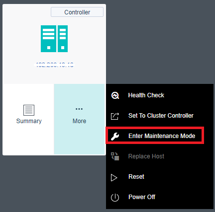
- After confirming that the node is turned off, remove the node from the shelf and expand the capacity. For details, please refer to the hardware operation guide below.
- After the hardware expansion is complete, put the node back on the shelf and join the original cluster. After the virtual storage task is executed, perform a Health Check (be sure to select the virtual storage data check).
Hardware Operation Guide
-
After confirming that the device is powered off, unplug the power cable, remove the server, lay it flat on a stable platform, and open the top cover of the chassis.
-
Read the memory installation sequence, and remember the memory installation slot to confirm whether the device has errors.
-
Press down on the memory’s left and right retaining clips to open left and right to eject the memory.
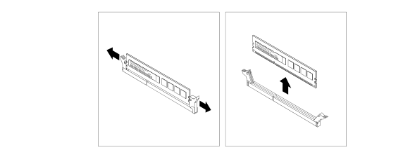
-
Touch the static-protective package containing the new memory module to any unpainted area on the outside surface of the server. Then, remove the memory module from the package (note: grasp the memory module’s edge and handle the memory module with care).
-
Verify that the memory model is correct.
-
Place the new memory module on the memory socket. Ensure the new memory module’s notch aligns with the memory socket’s protrusion. Then press the new memory module straight down into the memory socket until the securing clips are closed, and the new memory module snaps into place.
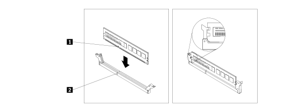
-
Check that no other debris is left in the chassis, and restore the cover.
-
Inspection after replacement:
After the normal startup, you need to enter the BIOS or the system to confirm whether the device has all the memory.
The BIOS confirmation method is as follows:
-
Check whether Main’s Total Menu value equals the total built-in capacity.
-
Such as 65536=64G, 131072=128G.
-
View Chipset Configuration > North Bridge > DIMM Configuration > DIMM Information in Advanced.
The figure below shows the usage of each memory slot.
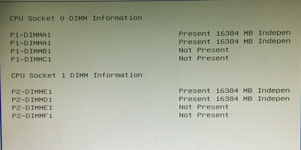
After entering the system, you can check the memory usage through the command to judge whether the recognition is complete.
There are many commands to use, but I will not list them one by one, as follows:
- Cat /proc/meminfo
- free -m
Attachment: memory slot insertion method
9S Series:
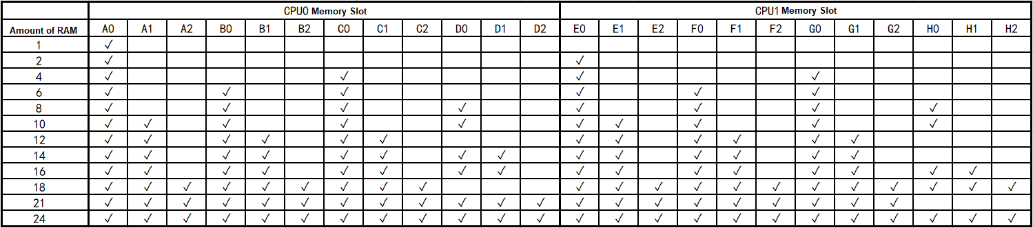
Notice:
The ✓ in the table indicates that the memory slot is installed with memory, and the blank indicates that no memory is installed.
Remove the top cover of the server. You can see the mark next to the memory slot on the motherboard. Refer to the figure below. When only one memory is inserted, insert the memory into the A0 slot; when four pieces of memory are to be inserted, insert the memory into the A0, C0, E0, G0 slots; and so on.
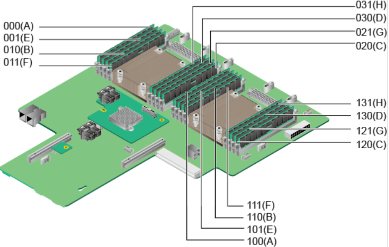
For devices starting with 9T, the memory insertion method is as follows.
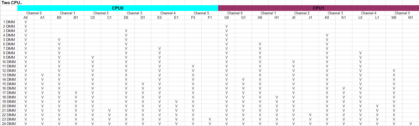
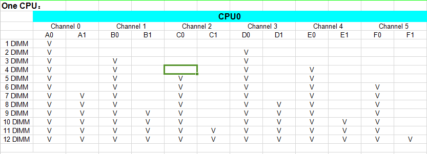
NIC Replacement
Description
- Replace when Sangfor aServer NIC needs to be upgraded and replaced (gigabit NIC is upgraded to 10 Gigabit NIC).
- When the number of existing NICs of the Sangfor aServer machine is small, which does not meet the best practice, it is necessary to add NIC.
- When the NIC of the Sangfor aServer machine fails, the NIC needs to be replaced.
- For non-aServer, you need to contact the server vendor, and the personnel of the corresponding vendor will operate and maintain it. Sangfor employees are not allowed to operate directly.
Precautions
- Please ensure that the NIC is in the compatibility list when upgrading or adding a NIC.
- It is recommended to use a NIC with the same model parameters as the original NIC for replacement.
Prerequisites
- Confirm the compatibility of the NIC. Please contact Sangfor technical support for evaluation if it cannot be determined.
- Confirm the node that needs to be upgraded, added, or replaced with NIC, and migrate the virtual machines and virtual devices running on the node to other nodes in the cluster to ensure uninterrupted services.
Steps
-
After confirming that the device is powered off, remove all external cables, such as power and network cables.
-
Remove the server from the cabinet and place it horizontally on a stable table.
-
Open the top cover of the chassis and remove the NIC fixing screws.
-
Hold both sides of the NIC with both hands and slowly pull out the NIC upwards.
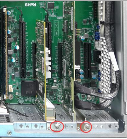
-
Verify if the adapter model is incorrect.
-
Hold both sides of the new network card and insert it into the corresponding slot.
-
Fasten with screws.
-
Check that no other debris is left in the chassis, and restore the cover.
-
Perform Health Check to confirm that the platform is operating.
RAID Card Replacement
Description
- When the Sangfor aServer RAID card fails, it needs to be replaced without stopping the business.
- For non-aServer, you need to contact the server vendor, and the personnel of the corresponding vendor will operate and maintain it. Sangfor employees are not allowed to operate directly.
Precautions
Confirm the server model and RAID card model. It is recommended to replace the RAID card with the same parameters as the original RAID card to ensure compatibility.
Prerequisites
- Confirm that the new RAID card is compatible with the server and supports the JBOD mode.
- Enter the maintenance mode for the node that needs hardware maintenance, and migrate the virtual machines running on the node to other nodes in the cluster to ensure uninterrupted services.
Steps
- Nodes starting with 9S.
-
After confirming that the device is powered off, unplug the power cable, remove the server, lay it flat on a stable platform, and open the top cover of the chassis.
-
Remove the PCI-E converter.
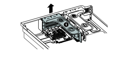
-
Unplug the 2 RAID cables connected to the adapter, and remember the wiring sequence (press the tab and pull out).
-
Remove the fixing screws of the RAID card, hold the edge of the RAID card, and remove the RAID card.
-
Confirm that the adapter model is correct.
-
Place the adapter card near the PCI-E slot. Then, carefully press the adapter straight into the slot until it is firmly seated. Make sure the riser bracket secures the adapter bracket.
-
Install the fixing screws and connect the RAID cables in sequence.
-
Put the converter card back into the chassis,
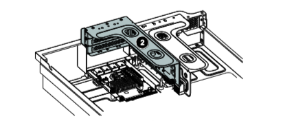
-
Check that no other debris is left in the chassis, and restore the cover.
- Nodes starting with 9W.
-
After confirming that the device is powered off, unplug the power cable, remove the server, lay it flat on a stable platform, open the top cover of the chassis, and remove the air duct.
-
Unplug the two RAID cables connected to the array card. Note that the two cables are in order (press the tabs and pull them out).
-
Remove the fixing screws.
-
Hold the two sides of the array card and pull out the array card upwards.

-
Confirm the adapter model.
-
Hold both sides of the new adapter and insert it into the corresponding slot.
-
Fix it with screws, and connect the RAID cable to the interface (note that the two cables need to be inserted back in the original order).
-
Check that no other debris is left in the chassis, and restore the cover.
- Nodes starting with 9L.
- After confirming that the device is powered off, unplug the power cable, remove the server, lay it flat on a stable platform, and open the top cover of the chassis.
- Loosen the screws that secure the riser card assembly. Then, hold the assembly by the edges and carefully lift the entire cage straight up from the chassis.
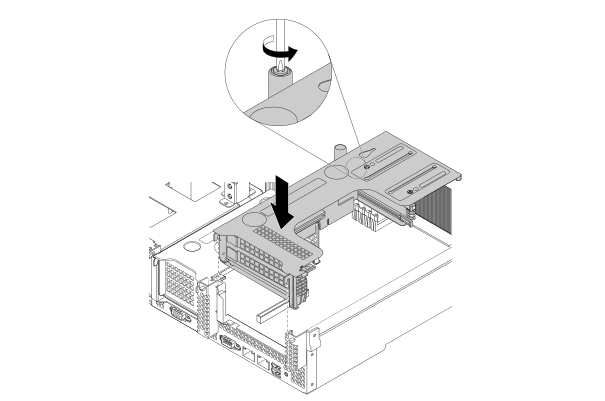
Notice:
If there are other PCIe cards in this fixing frame, please remove the connection cables first.
-
Unplug the 2 RAID cables connected to the array card (press the tabs and pull them out).
-
Locate the PCIe card you want to remove, then press the tab to rotate the latch to the open position.
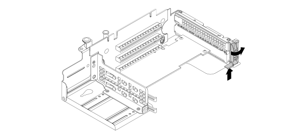
-
Holding the adapter by its edges, carefully pull it out of the PCIe slot.
Notice:
The adapter card may be firmly seated in the PCIe slot. If necessary, alternately move both sides of the adapter slightly and evenly until it is removed from the slot. The array card can also be pushed out through the 2 round holes of the fixing frame.
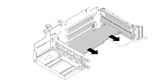
-
Confirm that the adapter model is correct.
-
Place the array card near the PCIe slot. Then, carefully press the adapter straight into the slot until it is firmly seated, ensuring the adapter bracket is secured by the riser bracket.
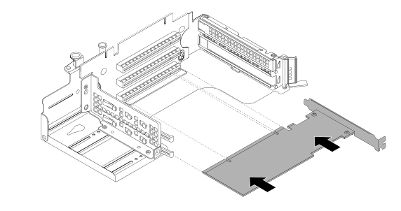
-
Rotate the latch to the closed position to secure the adapter in place.
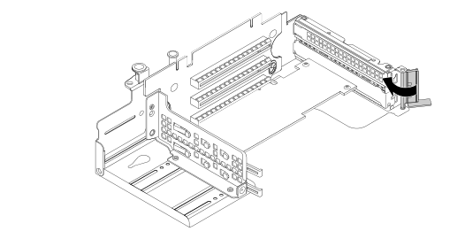
-
Connect the RAID cable back to the array card. Note that the two cables are in order. Port 0 on the RAID card is connected to the RAID cable 0-3. One port is connected to the 4-7 RAID cable.
-
Put the entire fixing bracket back into the chassis. Select and fix the component screws in the opposite direction.
-
Check that no other debris is left in the chassis, and restore the cover.
- Check after replacement
- Confirm that there is an array card in the bios power on option.
- Confirm that the hard disk in the array card is recognized and the mode is JBOD mode.
- Carry out a key check to confirm that the platform is running normally.
Power Module Replacement
Description
- When the power supply module of Sangfor aServer fails, the power supply needs to be replaced.
- For non-Sangfor aServer, you need to contact the server manufacturer, and the personnel of the corresponding manufacturer will operate and maintain it. Sangfor employees are not allowed to operate directly.
Precautions
- When the server is equipped with dual power supply modules, one is faulty, and the other runs normally. It can be replaced without interrupting services.
- When the server is configured with a single power supply module, and the power supply fails, if the node has not been powered off and shut down, it can be replaced without interrupting production.
- The model and parameters of the replaced power module must be the same as the original faulty power module.
Prerequisites
Confirm whether the server is configured with a single or dual power supply module and make a replacement plan.
Steps
In these steps, the server is configured with dual power modules, and one of them is faulty.
When the server is configured with a single power supply module, the power supply fails, and the node has not been powered off and shut down, the virtual machines and virtual devices on the node can be migrated to other nodes to ensure uninterrupted services. Then power off the server and replace the power module.
-
Unplug the faulty power supply cable, press the release tab in the direction shown in the figure, and at the same time, carefully pull the handle to pull out the faulty power supply from the chassis.
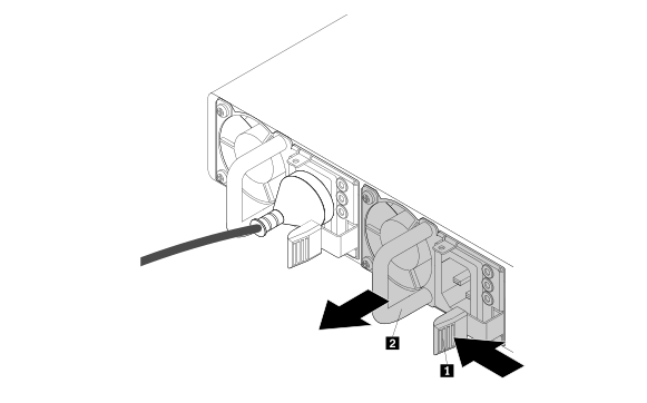
-
Double-check that the new power supply model matches the device.
-
Push the new power supply module into the chassis until it clicks into place and connects the power cord.
-
Detection after replacement
- Check whether the power indicator is normal.
- Check whether the device is powered on normally and runs normally.
- Enter the IPMI to check whether the output status of the power supply voltage is normal (usually in the power supply options under the asset information or parts information).
- Perform Health Check to confirm the normal operation of the platform.
Platform High-Risk Operations
Interface Configuration High-risk Operations
Change the Storage Communication Network Port
Description
The administrator must modify the configuration of the storage network interface to match the new communication method.
Risk Details
- Changing the communication port of the storage interface may cause risks such as abnormal communication between virtual machines and service interruption.
- At present, the platform has restricted the change of storage communication. All virtual machines must be shut down to make changes to prevent the virtual machines from running abnormally.
Correct Method
Shut down all running virtual machines, and then change the cluster storage interface.
Formatting the Cluster
Description
The administrator restores the factory settings in HCI.
Risk Detail
All data in the cluster, including virtual machines, backups, and virtual network devices, will be formatted and restored to the factory state.
Correct Method
Make sure that there is no available data in the current cluster. If you need the relevant virtual machine, please use the export image to save it.
Cluster Backup and Recovery
Description
The administrator cannot perform any action and needs to restore the backup to a certain point in time.
Risk Detail
Restoring backup results in data loss from the restoration time to the current time.
Correct Method
Please confirm that there is no other way to deal with it, and save the relevant data for backup and recovery.
Recycle Bin
Description
Clear the data in the HCI Recycle Bin.
Risk Detail
Empty the recycle bin will cause the data in the recycle bin to be emptied, and the data will not be able to restore.
Correct Method
Confirm the data you need to use before emptying the recycle bin.
Hardware Hazardous Operations
Reinstalling The System for Servers Not Joined to A Cluster
Description
The Sangfor aServer where the Sangfor HCI system is located is not added to the reinstallation.
Risk Detail
Reinstalling the system will result in the loss of the signature of the aServer, which will cause the server to be unable to join the Sangfor HCI cluster.
Correct Method
Before and after reinstallation, users need to call Sangfor technical support.
Reinstalling The System for Servers That Joined the Cluster
Description
Reinstall the Sangfor aServer or third-party server where the Sangfor HCI system is located.
Risk Detail
- Causes the virtual machine running on the server to use the None method.
- As a result, the signature of the aServer machine is lost, causing the server to be unable to join the Sangfor HCI cluster.
Correct Method
- Users should avoid such operations.
- When this problem occurs, you need to call Sangfor technical support.
Changing the Physical Network
Description
Change the network during business operations, such as changing the HCI platform to use switch port VLAN, IGMP snooping, MTU, and STP protocols, plugging and unplugging server network cables, replacing server NIC, etc.
Risk Detail
- It may cause business exceptions or even None access.
- Storage network changes may result in virtual machine migration or even data loss.
Correct Method
- Users should avoid such operations.
- When such operations are necessary, call Sangfor technical support.
Unplug And Plug Server Disks at Will
Description
Feel free to plug and unplug the disks that have been added to the Sangfor HCI server.
Risk Detail
- Randomly plugging and unplugging disks can cause inconsistencies between distributed replicas.
- Distributed storage data may be lost.
Correct Method
Users should prohibit such operations.
Formatting The Server Disk
Description
Format the server disk or external storage disk that has joined the Sangfor HCI cluster.
Risk Detail
It will lead to the loss of stored data, and in severe cases, it may lead to the entire virtual machine not being usable.
Correct Method
Users should prohibit such operations.
iSCSI Storage Rescan or Target Rediscovery
Description
For the running business virtual machine, and the virtual machine’s datastore is on the iSCSI server connected to HCI, perform the Rescan or Discover Target operation.
Risk Detail
It will trigger the reconnection of iSCSI connection update interruption, resulting in abnormal IO progress, thus affecting the normal access of the business system and leading to business interruption.
Correct Method
Before performing such operations, make sure that the business system on the iSCSI storage can be shut down.
Network Port Table
| Source Device | Src port | Dst device | Dst port | Protocol | Product Description |
|---|---|---|---|---|---|
| management terminal | any | HCI | 80 | http | HCI web admin console jumps to port 443. |
| management terminal | any | HCI | 443 | https | HCI web admin console login port. |
| HCI | any | HCI | 4099 | udp | Used to discover physical nodes with HCI installed. |
| HCI | any | HCI | 7001-7019 | tcp | For intra-cluster and cross-cluster virtual machine migration. This port will be automatically enabled when the cloud management platform manages the cluster. |
| Host to be migrated | any | HCI | 4000-4010 | tcp/udp | When using a converter or ISO to perform p2v tasks, discover the ports used by the node. |
| Host to be migrated | any | HCI | 10809-10900 | tcp/udp | When using a converter or ISO to perform p2v tasks, copy the port used by the disk. |
| management terminal | any | HCI | 139,445 | tcp | Samba shared directory management service, providing file sharing functions. |
| Third Party Server | any | HCI | 4433 | tcp | Provide API interface to third-party calls (SCMT uses this port). |
| Monitoring and management equipment | any | HCI | 161 | udp | The SNMP service helps administrators understand the physical resource usage at runtime. |
| HCI | any | HCI | 22 | tcp | For node expansion, node replacement, and connection to the node during the inspection. |
| management terminal | any | HCI | 4480 | tcp | Access the web admin console of the NFV appliance |