【NGAF】Bridge Mode Deployment Configuration Guide_V8.0.47
Introduction
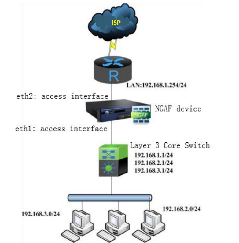
NGAF deploy in bridge mode belongs to a Layer 2 network device. Therefore, it can implement all the security functions of the firewall, such as Access control, bandwidth management, DNS mapping, etc. (except for the functions of the route interface).
Scenario
The firewall security feature needs to be implemented without changing the current network environment of the customer.
Preparation
- A designated network topology environment.
- An NGAF device.
Configuration
Interface/ Zone
- Navigate to Network > Zone > Add, add LAN, WAN, and Management zone as the figure below:
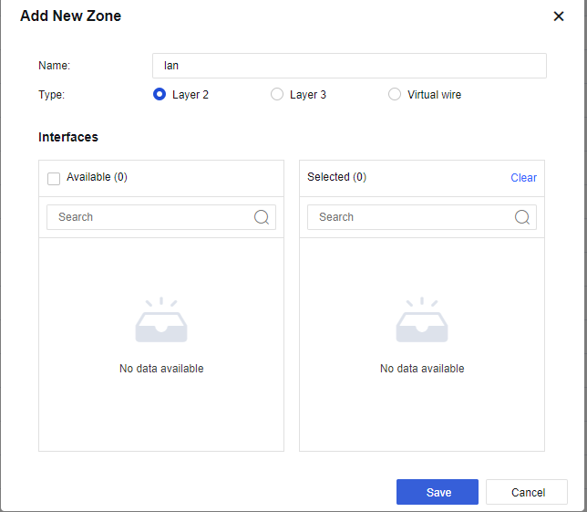
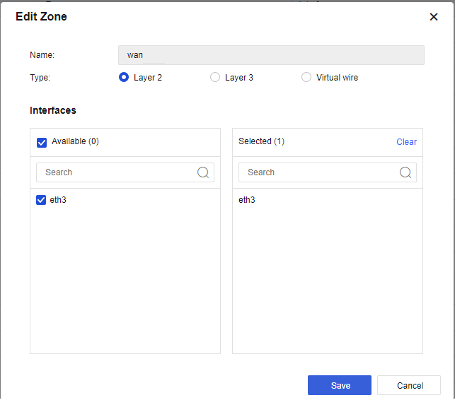
Note:
Management is Layer 3 ZONE.
- Navigate to Network > Interfaces > Physical Interface, select the interface and configure the WAN interface as shown in the figure below:
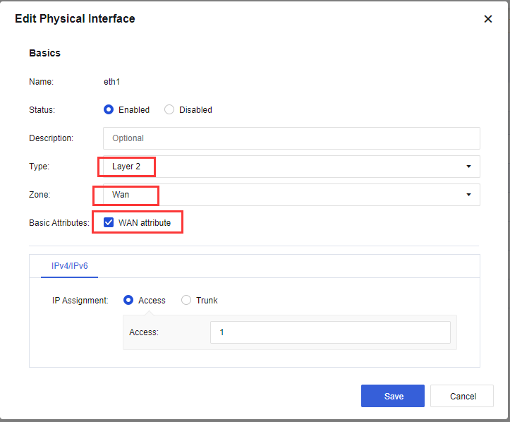
Note:
The connection type is Access or Trunk. Generally, the Access interface belongs to VLAN 1 and can be modified or set to other VLANs. However, the two interfaces of the device must be in the same VLAN. In Trunk mode, native 1-1000 does not need to modify. Users can set the VLAN range to the VLAN number that needs to be penetrated by the device.
- Navigate to Network > Interfaces > Physical Interface, select the interface and configure as LAN interface as shown in the figure below:
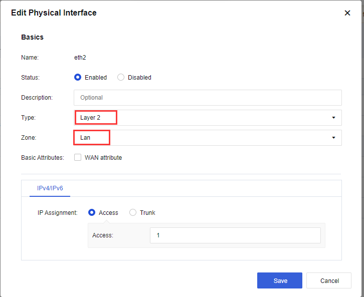
Note:
The connection type is Access or Trunk. Generally, the Access interface belongs to VLAN 1 and can be modified or set to other VLANs. However, the two interfaces of the device must be in the same VLAN. In Trunk mode, native 1-1000 does not need to modify. Users can set the VLAN range to the VLAN number that needs to be penetrated by the device.
- Navigate to Network > Interfaces > VLAN interface > Add, add a VLAN interface as shown in the figure below:
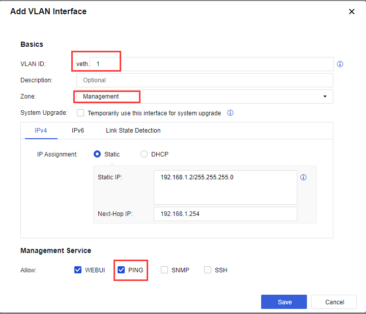
Note:
Link State Detection is used to detect the quality of the link. The link detection method includes ARP probe, DNS lookup, and PING. The user is recommended to use PING and fill in the PING detection IP address.
Routing
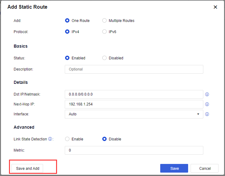
- Navigate to Network > Routes > Static Route > Add to add a default route as shown in the figure below:
Default Route:
Return Route:
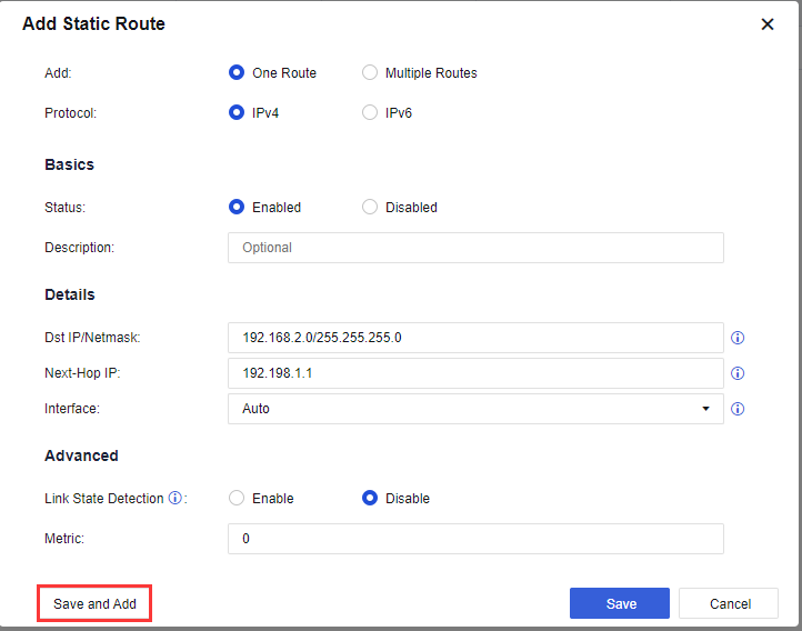
Note:
Destination IP is the intranet user network segment. Next-Hop IP is the device’s gateway.
Access Control Policy
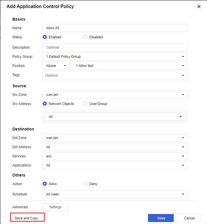
- Navigate to Policies > Application Control > Policies > Add, add an Allow All policy as shown in the figure below:
-
Policy Group: Choose the default group.
-
Source:
-
Src Zone: Select WAN and LAN zone.
-
Src Address: Select Network Object and ALL.
-
Port: All is selected by default.
-
-
Destination:
-
Dst Zone: Select WAN and LAN zone.
-
Dst Address: Select ALL.
-
Service: Select Any.
-
Application: Select All.
-
-
Others:
- Action: Select Allow.