【NSF】User Manual_V8.0.85
Overview
Introduction
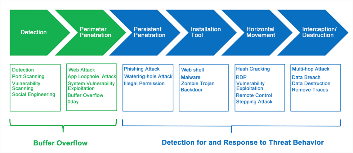
Sangfor Network Secure has the capabilities of risk prediction, deep security protection, and detection response, forming an integrated security system with whole-process protection and visibility.
Integration is not a simple function superposition, but integration of technical security means provided for the risks encountered in the service development process. It gives whole-process protection to the service. Integrated security includes asset risk discovery, policy detection, various security defense methods that should be available during the incident, continuous detection, and rapid response mechanisms after the incident.
Key Features
I. Preparation & Prediction: Asset/Vulnerability/Policy Effectiveness
Network Secure can automatically identify risks such as open ports, vulnerabilities, and weak passwords on internal servers in advance and judge whether the identified assets have corresponding security protection policies and are in effect.
II. Real-Time Defense: Complete Defense System + Security Correlation + Threat Intelligence
Network Secure integrates several security technologies for effective defense during an event. It provides a complete security defense system (L2-L7) to ensure no weaknesses in security protection. At the same time, Network Secure can also improve the timeliness and effectiveness of the defense system through security integration, including integrating cloud and endpoint security solutions and coordinating different modules. In addition, Network Secure also cooperates with third-party security agencies and utilizes threat intelligence from multiple sources, such as the Chinese National Vulnerability Database, VirusTotal, and malicious URL databases, to help users prepare for defense before security events occur.

III. Post-event Detection & Response: Continuous Detection of Threatening Behaviors and Rapid Response
Traditional security work mainly focuses on border security defense and cannot detect and respond when attackers bypass security measures. If there are mature post-event detection and response measures, the impact of security events can be greatly reduced. Network Secure integrates post-event detection and rapid response technologies, which help users timely discover malicious behaviors even after hacking, such as detecting malicious behaviors initiated by zombie computers, webpage tampering, website backlink embedment, and Webshell backdoor, and quickly push alarm events to assist users in responding and handling.
Installation and Deployment
This section mainly describes the installation preparation, including tools, installation environment, and software and hardware.
Installation Preparations
Environment Requirements
Network Secure can be used in the following environments. To ensure the long-term stable operation of the system, the power supply should be properly grounded, and the operating environment features dustproof measures, smooth air, and stable room temperature. This product complies with the design requirements for environmental protection. The placement, usage, and abandonment of the product shall comply with relevant national laws and regulations where it is applied.
| Parameter | Requirements |
|---|---|
| Voltage | 110V~230V |
| Temperature | 0~45°C |
| Humidity | 5~90% |
| Power supply | 110V AC to 230V AC: Please ensure the power supply has good grounding measures before switching on the power. |
Table1: Operating Environment Requirements for Network Secure
Product Appearance
Network Secure’s front panel is shown below (Network Secure-2000-B2150 as an example).
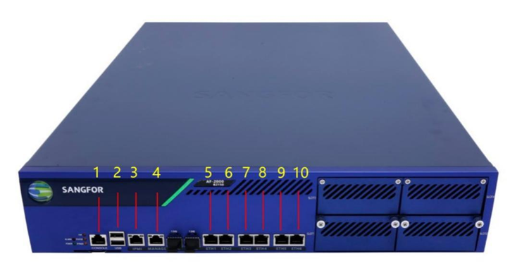
| Device Name | No. (Front) | Note |
|---|---|---|
| Network Secure-2000-B2150 | 1 | CONSOLE interface |
| Network Secure-2000-B2150 | 2 | USB interface |
| Network Secure-2000-B2150 | 3 | IPMI interface |
| Network Secure-2000-B2150 | 4 | MANAGEMENT interface (ETH0) |
| Network Secure-2000-B2150 | 5 | ETH1 |
| Network Secure-2000-B2150 | 6 | ETH2 |
| Network Secure-2000-B2150 | 7 | ETH3 |
| Network Secure-2000-B2150 | 8 | ETH4 |
| Network Secure-2000-B2150 | 9 | ETH5 |
| Network Secure-2000-B2150 | 10 | ETH6 |
Table 2: Networking Interfaces of Network Secure-2000-B2150
Network Secure’s rear panel is shown below (Network Secure-2000-B2150 as an example).

| Device Name | No. (Rear) | Note |
|---|---|---|
| Network Secure-2000-B2150 | 1 | POWER button |
| Network Secure-2000-B2150 | 2 | POWER interface |
| Network Secure-2000-B2150 | 3 | POWER interface |
Table 3: Interfaces on Rear Panel (Network Secure-2000-B2150)
Precautions:
-
The alarm indicator is steady red when the device is running. Generally, the red alarm indicator goes out after one or two minutes, indicating the device is successfully turned on. If the red alarm indicator does not go out for a long time, please turn off the device and wait for 5 minutes before turning it on.
-
If the red alarm indicator remains on, please contact Sangfor Technical Support to determine whether the device is damaged. After the normal startup, the indicator may blink red sometimes. It is normal as the device is generating a system log.
-
The CONSOLE interface is for development, testing, and debugging only. End-users need to access the device by the networking interface and logging in to the console.
Configuration and Management
Before configuring the device, you need to prepare a computer and check whether the computer’s web browser works(such as Internet Explorer, Google Chrome, Firefox, and other mainstream browsers). Then, you can connect the computer to the Network Secure device in the same LAN and configure it over the network.
Cable Connection for a Single Device
-
Plug the power cable into the device’s rear panel, and then press the POWER button. At this time, the POWER indicator light (green) and the ALARM indicator light (red) on the front panel will be on. The ALARM indicator light will go out in one or two minutes, indicating that the device works.
-
Connect the ETH0 interface to a computer with a standard RJ-45 Ethernet cable, then change the computer NIC to 10.251.251.x/24 segment, then configure the Network Secure device.
-
Use standard RJ-45 Ethernet cable to connect the ETH2 interface to the Internet access device, such as routers, optical fiber transceivers, or ADSL Modem.
Precautions
-
The multi-line Network Secure device supports multiple Internet lines. At this time, the ETH2 interface is connected to the second Internet access device. The ETH3 interface is connected to the third Internet line, and so on.
-
Use the standard RJ-45 Ethernet cable to connect the DMZ interface to the DMZ network. Generally, the DMZ is equipped with web servers, e-mail servers, etc., that provide services for the outside. Network Secure can provide security protection for these servers.
-
When the device works, the POWER and LINK indicators for both the WAN and LAN interface will stay on. The ACT indicator will keep blinking when there is data traffic. The ALARM indicator is constantly red (for about one minute) only when the system loads after startup and goes out when the system is working. If the indicator light (red) stays on during installation, please power off and restart the device. If the red light is still on after startup, please contact us.
-
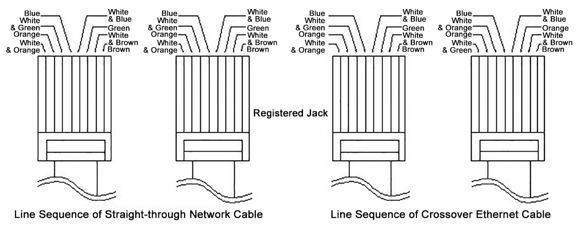
Use a straight-through network cable to connect the WAN interface to the MODEM and a crossover Ethernet cable to connect to the router. Use a straight-through network cable to connect the LAN interface to the switch and a crossover Ethernet cable to connect to the networking interface of the computer. When the indicator light is in normal status and the connection fails, please check whether the cables are connected correctly. The difference between the straight-through network cables and the crossover Ethernet cables lies in the wire sequence at both ends of the cables as follows.
Cable Connection for Active Standby Mode
If the Network Secure works in active standby mode, LAN and WAN cables are connected according to the following instructions.
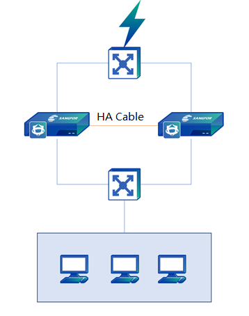
Use standard RJ-45 Ethernet cables to connect the ETH2 (WAN1) interfaces of two Network Secure devices (the connection method is similar if multiline technology is applied so that the WAN interfaces of two devices can connect to the same WAN line) to the same switch.
Use the standard RJ-45 Ethernet cables to connect the interfaces with Internet access devices, such as routers, optical fiber transceivers, or ADSL Modems.
- Select an idle network interface as the HA interface, and connect the HA interfaces of two Network Secure devices with a network cable.
- Use a standard RJ-45 Ethernet cable to connect the ETH0 (LAN) ports of the two Network Secure devices to the same switch, and then use a standard RJ-45 Ethernet cable to connect to the LAN switch and connect to the internal LAN.
- After wiring, power on the two devices respectively to configure the system. The way to configure a dual-system is no different from the single-system configuration. Configure the active device and the standby device will be synchronized automatically.
Login to Web Admin Console
Network Secure supports secure HTTPS login, which uses the standard port of the HTTPS protocol to prevent security hazards arising from interception during configuration.
The default IP address of the eth0 networking interface of the Network Secure device is eth0: 10.251.251.251/24.
If the computer is connected to the eth0 port of the device, you need to configure a 10.251.251.0/24 network segment address on the computer first, open the browser, and enter https://10.251.251.251 to log in to the device gateway console.
Operation Steps:
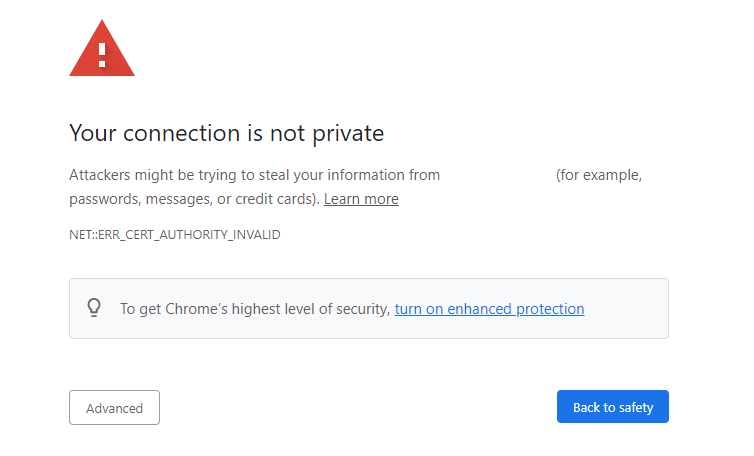
- First, configure the device’s IP address or network segment 10.251.251.X (for example, 10.251.251.100). Then, enter the URL https://10.251.251.251 in the browser. A security warning page, as shown below, will be displayed. Click Advanced and then Go to this page to jump to the console login page.
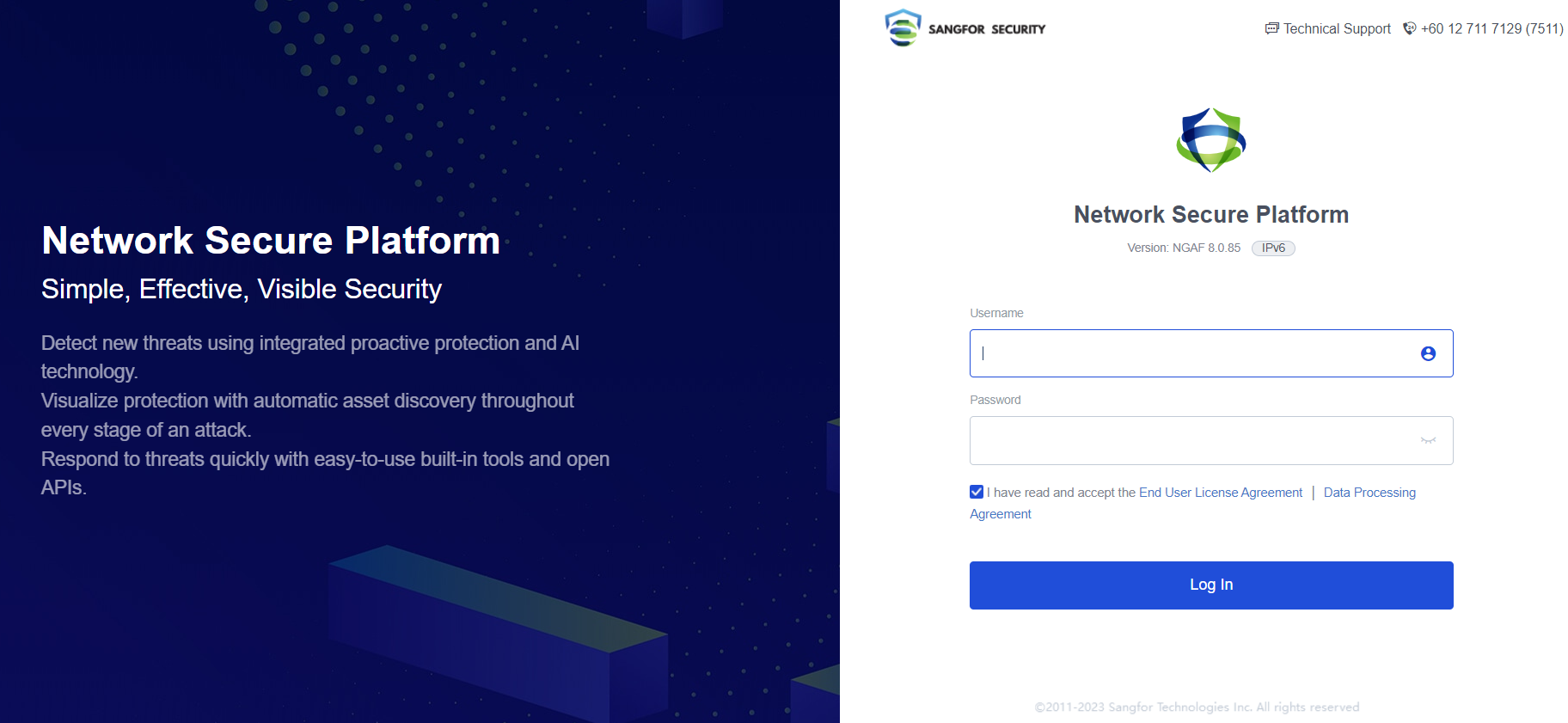
- Enter the username and password in the login box, which are both "admin" by default. Read the User Agreement and Privacy Policy (please contact Sangfor if you have any questions about the agreement). Check I have read and accept the End User Agreement, and then click Log In to log in to the Network Secure device to complete the configuration.
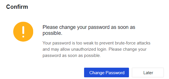
- If the password is too simple, it will be detected as a weak password, and the console will give a warning. If the password is deemed too weak after login, the following prompt window will appear.
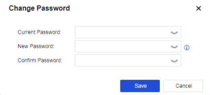
- Click Change Password. On the page displayed, you can change your password.
CLI Login
Network Secure also supports secure SSH login. After logging in, you can manage devices by using the command line.
Operation Steps:
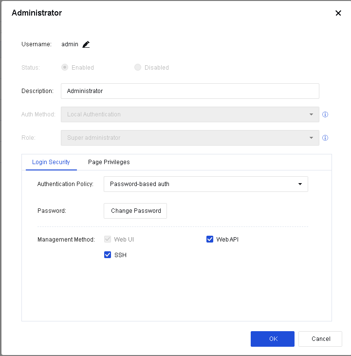
- Log in to the Web UI and go to System > Administrator. On the Administrator page, select an account and check SSH option in Management Method.
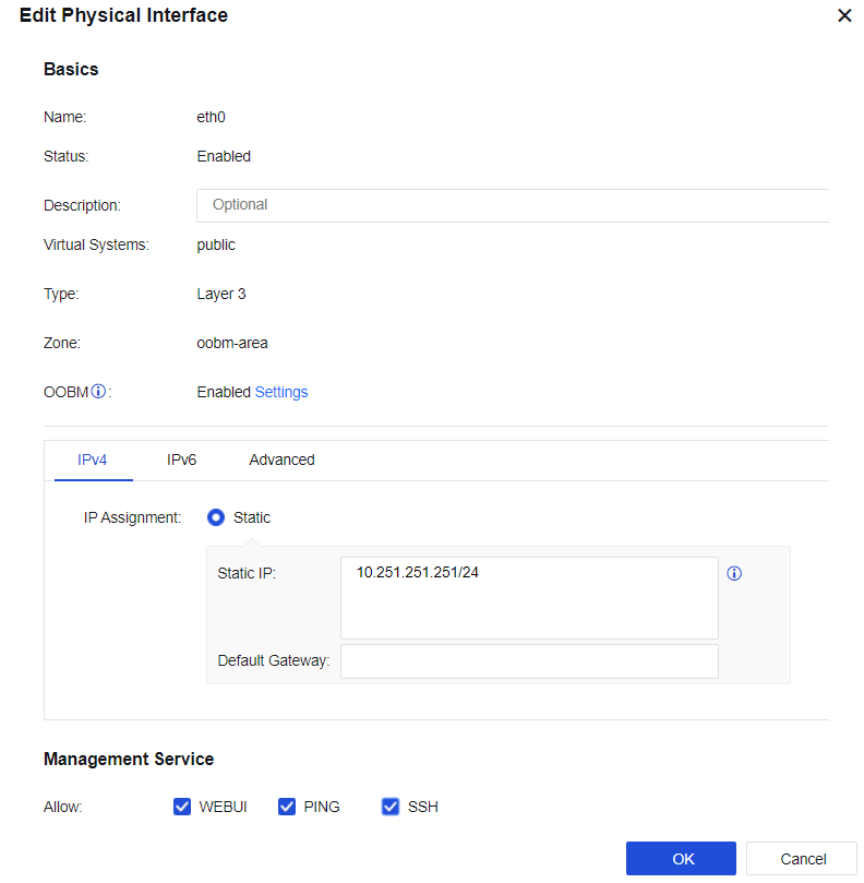
- Go to Network > Interfaces. Select a network interface and enable SSH in Management Service.
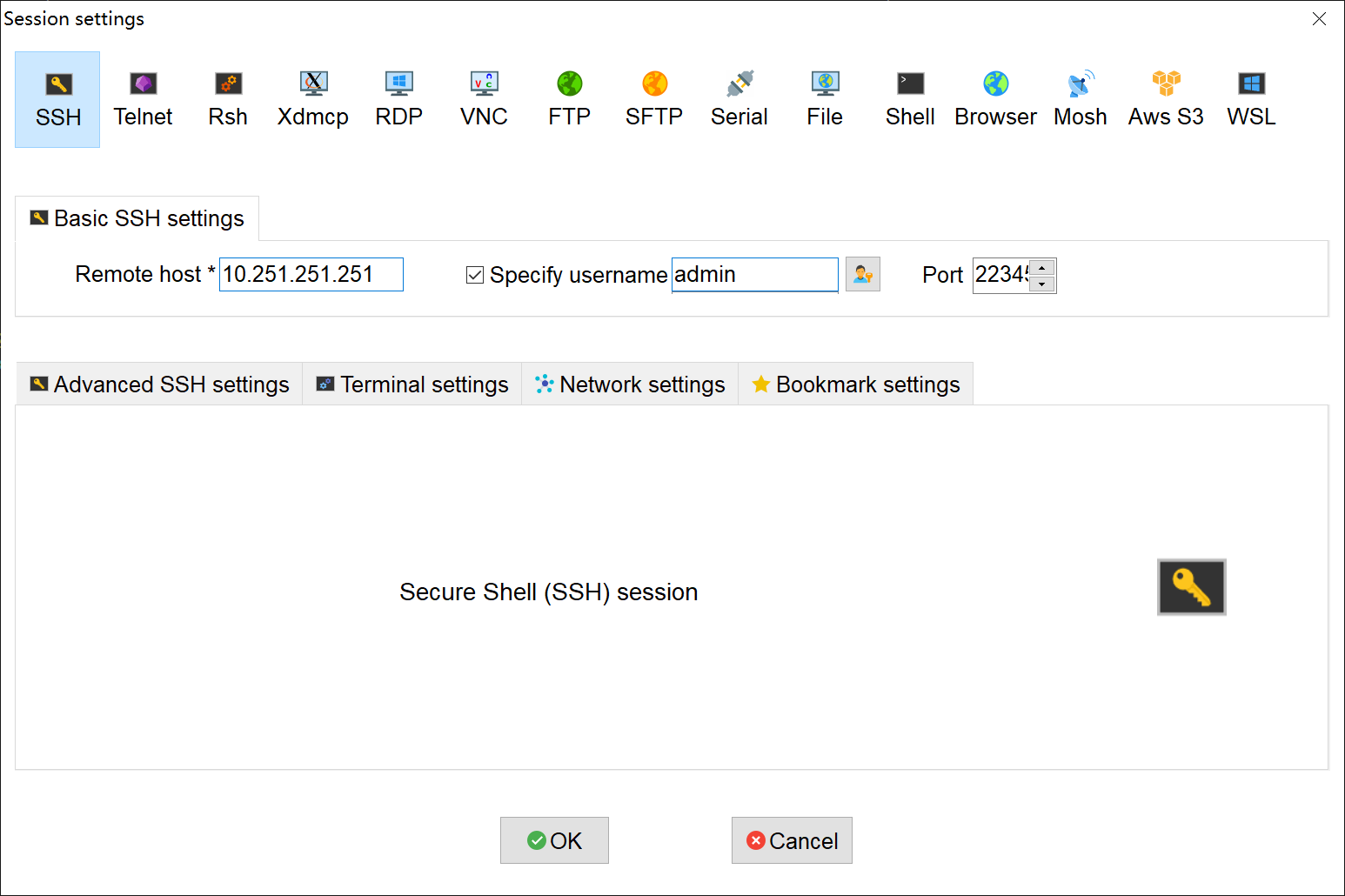
- Open the SSH management tool, set the port to 22345, and enter the administrator username and password to log in.
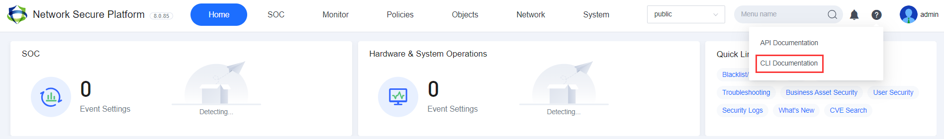
This manual does not describe the specific command parameters supported in the command line management mode. For more information, view the CLI Documentation, as shown below.
Deployment Mode
The deployment mode refers to the operating mode set for the device. You can set the device to the routing mode, transparent mode, Virtual Wire mode, bypass mode, and blend mode. An appropriate deployment mode is the precondition for successfully connecting the device to the network and making it work.
| Deployment Type | Scenario Description |
|---|---|
| Routing mode (Layer 3) | The device can be used as a routing device, which changes the network the most but can realize all the device’s functions. |
| Transparent mode (Layer 2) |
The device can be regarded as a network cable with a filtering function. This mode is usually enabled when changing the original network topology is inconvenient. It can provide most of the device’s functions by connecting it to the network seamlessly. |
| Virtual wire mode | This is another special type of transparent deployment, which does not need to check the MAC table and directly forwards it from the interface paired with the virtual network cable. The forwarding efficiency of the Virtual Wire is higher than that of the transparent mode. |
| Mirror mode | The device is connected to the mirror interface or HUB of the LAN switch, mirroring the data of LAN users and detecting the traffic through the mirrored data. There is no need to change the user’s network environment at all, and it can avoid the risk of interrupting the user’s network by the device. However, in this mode, the device only detects traffic and cannot block malicious traffic. |
| Mix mode | It mainly refers to layer 2 and layer 3 interfaces on the device, especially when the IP address of the Internet must be configured for DMZ’s server cluster. |
Table 4: Deployment Modes
Routing Mode (Layer 3)
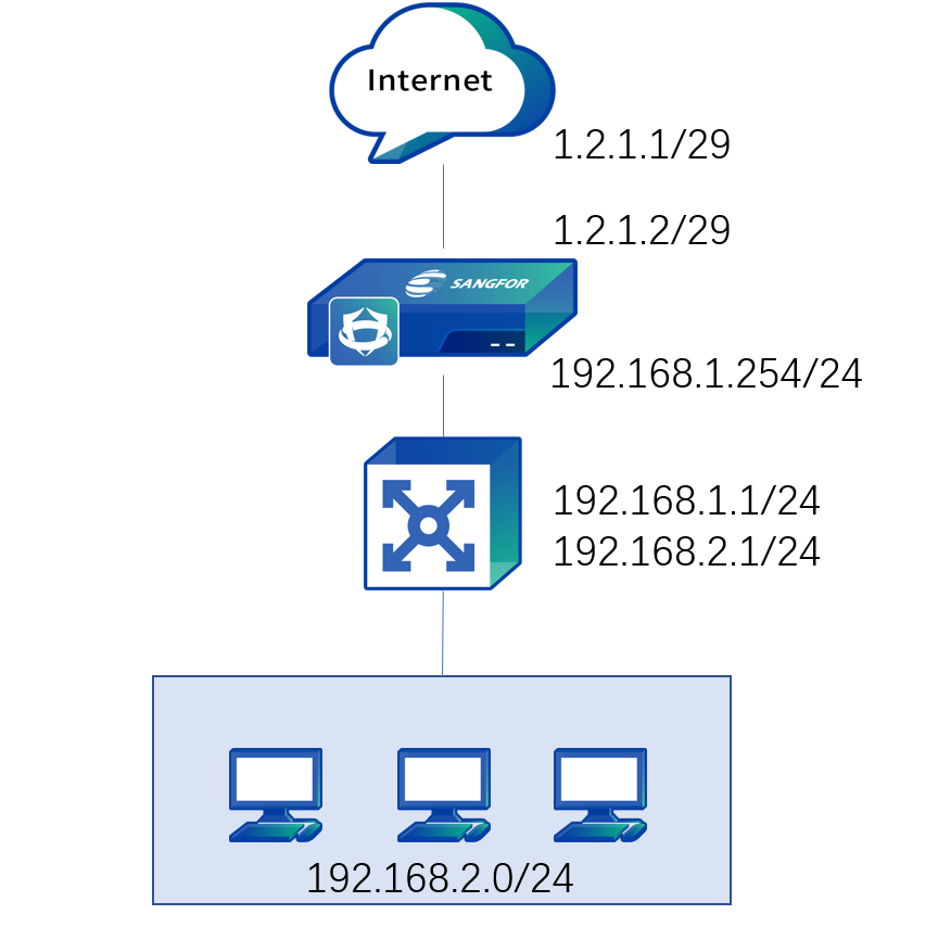
A typical application environment for routing deployment is to deploy a Network Secure device in the routing mode at the Internet port as a proxy of the LAN. The device is deployed like a router in the network. The WAN port is connected to the ADSL dial-up or Internet line, while the LAN port is to the LAN switch.
Deployment Case of Routing Mode
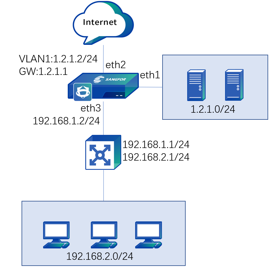
An enterprise network is a layer 3 environment. It is planned to deploy the Network Secure device at the Internet port as a proxy of the LAN. The Internet line is connected to the fixed IP address via optical fiber, as shown below:
-
Log in to the device through the default IP address of the management interface (ETH0). The default IP address of the management interface is 10.251.251.251/24. You need to configure an IP address in the same network segment on the computer and log in to the device via .
-
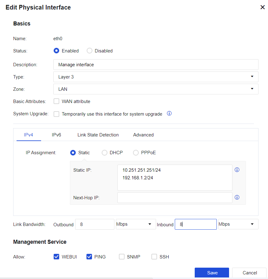
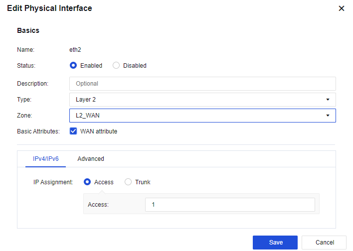
Configure the WAN interface: Click the interface to be set as the WAN interface through Network > Interfaces > Zone. Select eth2 as the WAN interface, select Layer 3 for Type and the WAN for Zone, check the WAN attribute checkbox, and configure an IP address 1.2.1.2/29 and the next-hop address 1.2.1.1, etc. See the figure below:
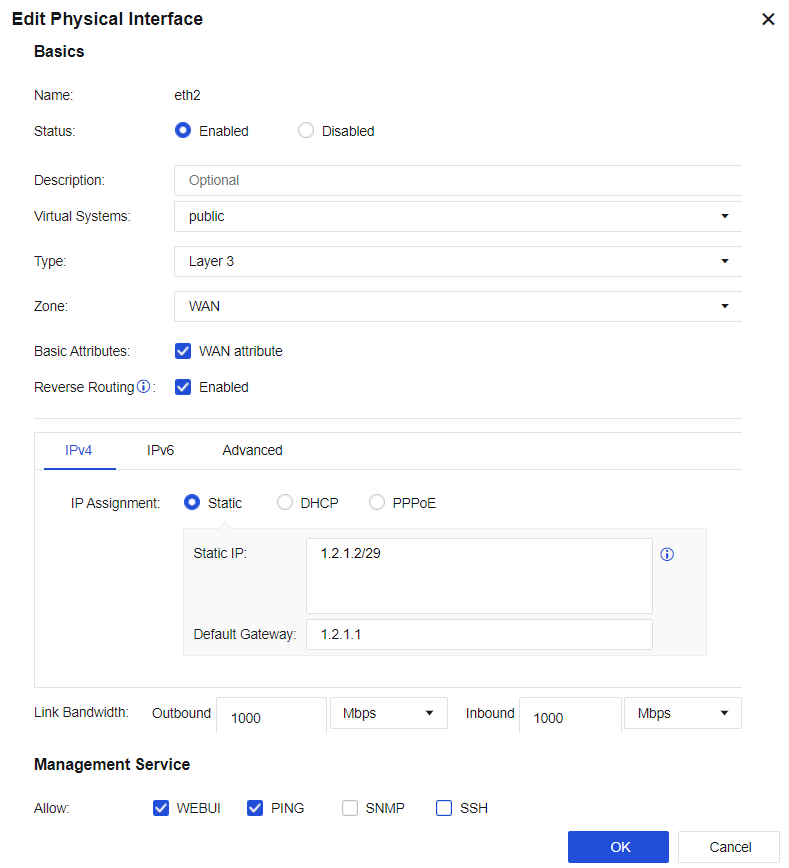
Notice:
The next-hop gateway of an interface is only applied to the link detection and policy-based routing functions. Setting the next-hop gateway does not generate a 0.0.0.0/0 default route on the device. Therefore, you need to configure the default route.
The line bandwidth setting of an interface is not associated with traffic management, and the line bandwidth setting at the interface is used for scheduling policy-based routing.
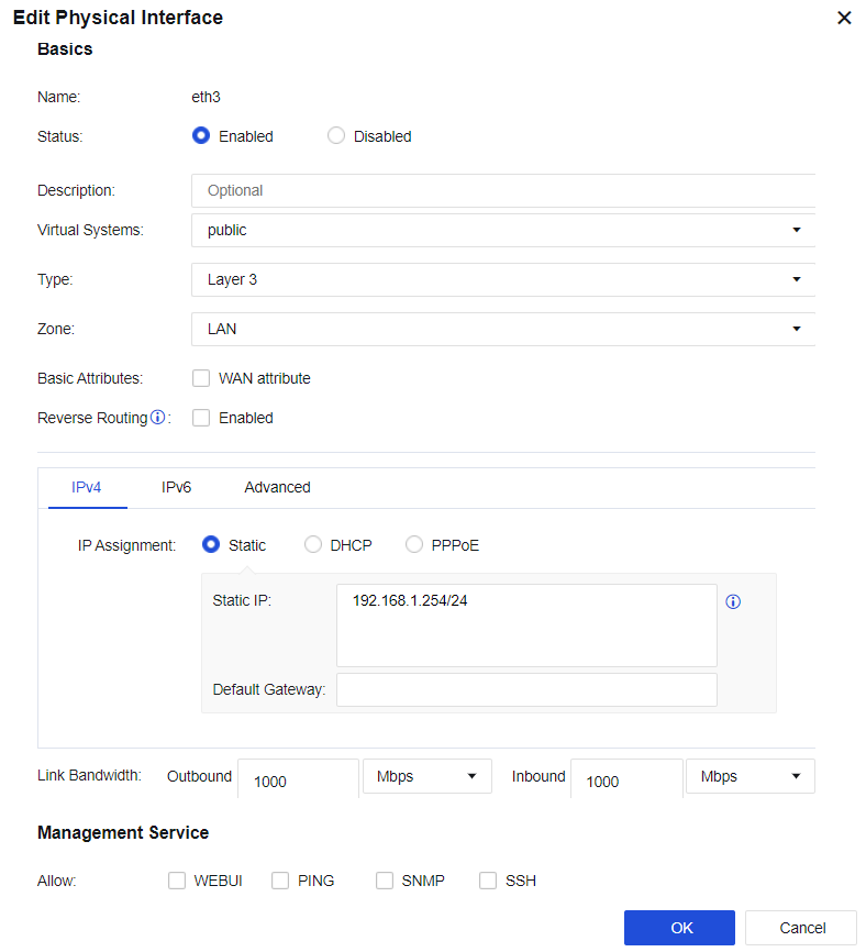
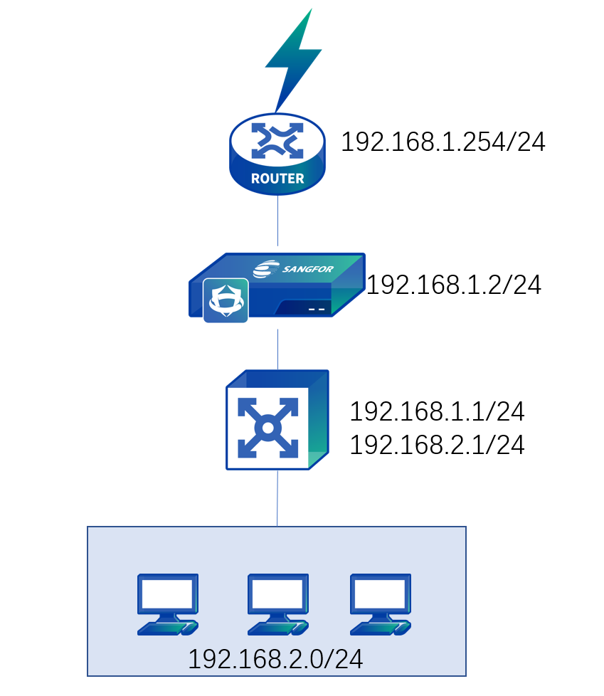
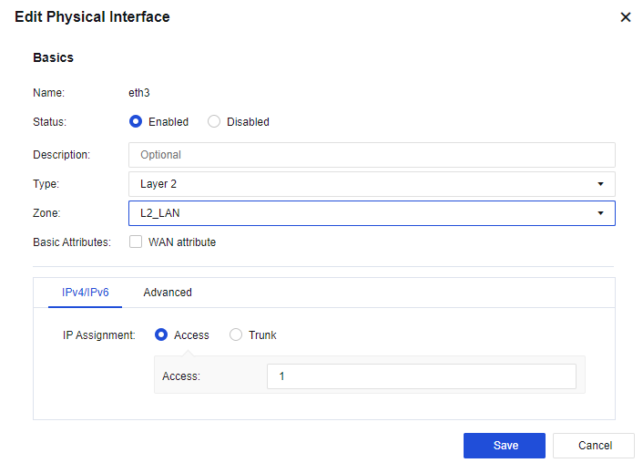
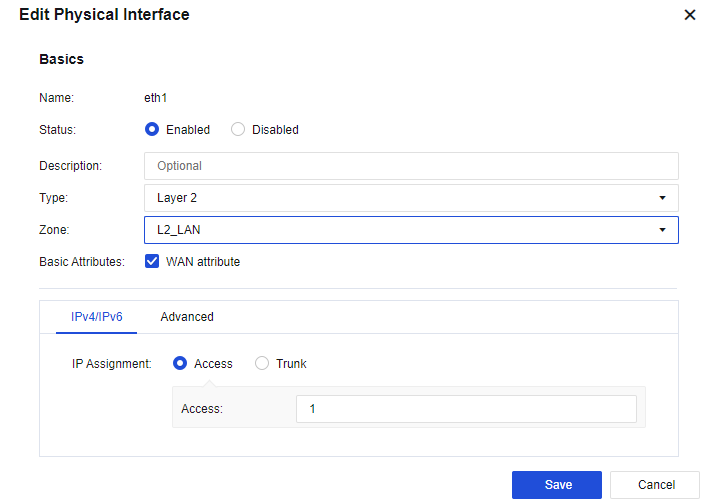
- Configure the LAN interface: Select an idle networking interface and click on the interface name to go to the configuration page. Then, select eth3 as the LAN interface, select Layer 3 for type and the user-defined LAN area, and configure an IP address 192.168.1.254/24, as shown below:
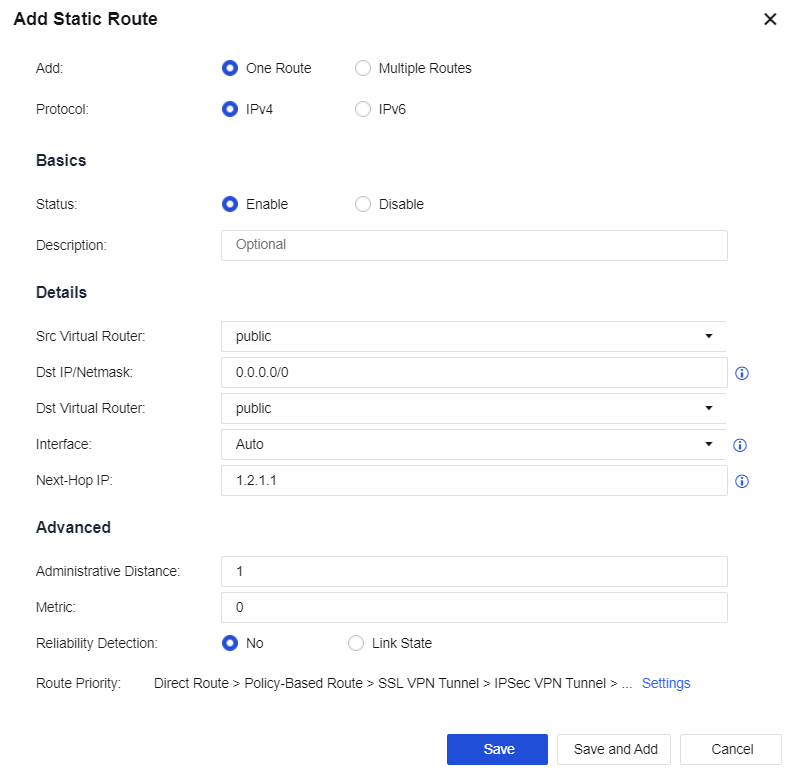
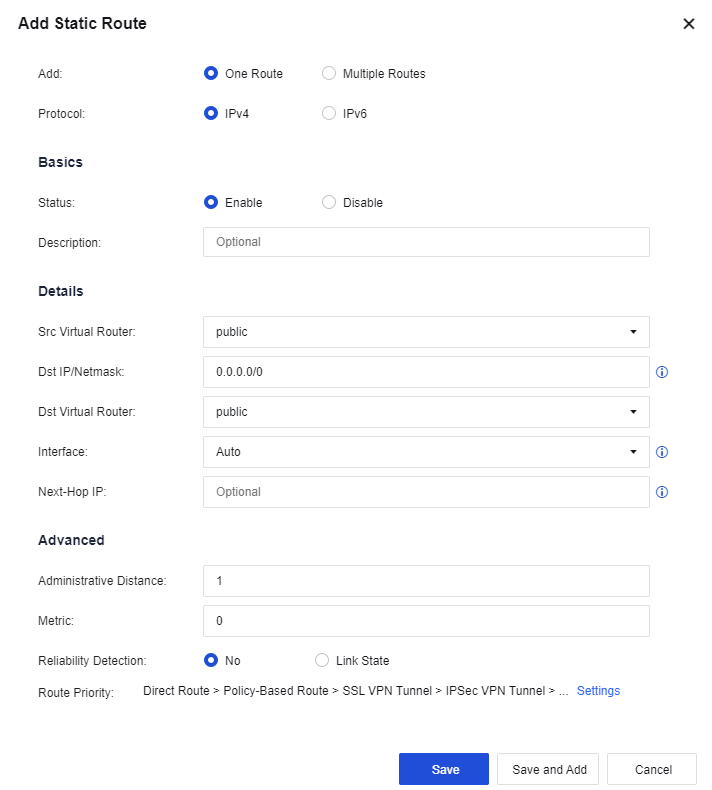
- Configure a route: You need to configure a default route to 0.0.0.0/0.0.0.0, pointing to the next hop 1.2.1.1. Meanwhile, the LAN interface is connected to multiple network segments accross layer 3. In this case, you need to configure another static route containing each network segment to the layer 3 switch. Go to the Network > Route > Static Route page and click Add to add a static route.
Configure the default route Dst IP/Netmask as 0.0.0.0/0 and the Next-Hop IP as 1.2.1.1 and configure the return route (LAN segment return route) Dst IP/Netmask as 192.168.2.0/24 and the Next-Hop IP as 192.168.1.1. See the figure below:

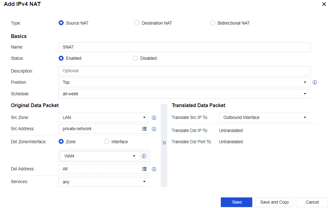
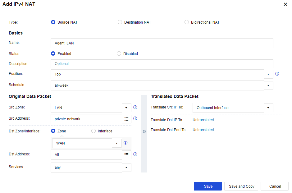
- Configure the SNAT: Go to Policies > NAT > IPv4 NAT. Click Add to configure the SNAT. Select the custom LAN zone as the Src Zone, the custom LAN address as Src Address, the custom WAN zone as Dst Zone, All for Dst Address, any for Services, and Outbound Interface for Translate Src IP To. See the figure below:
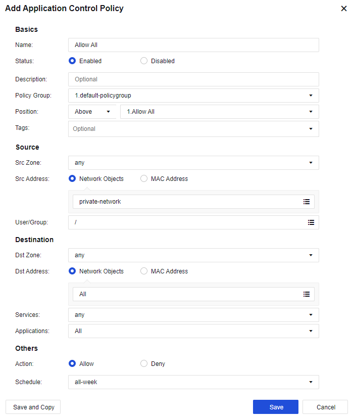
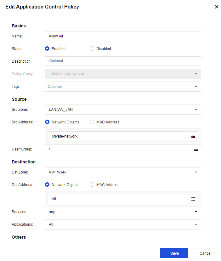
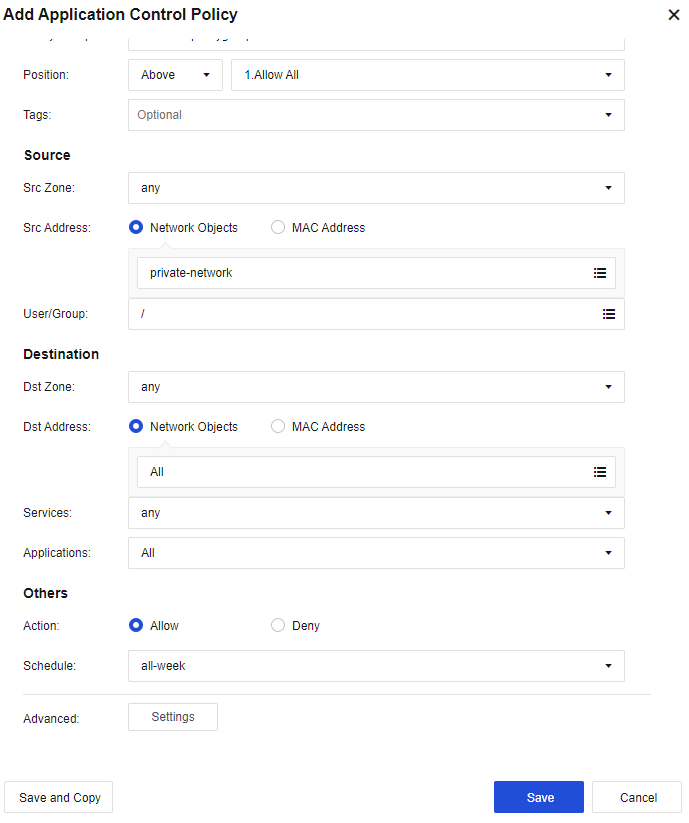
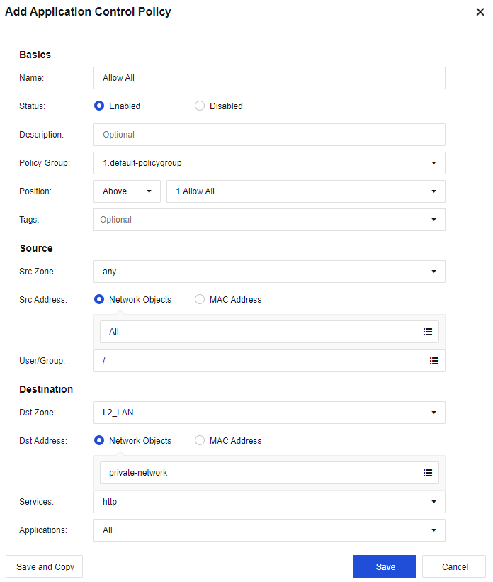
- Configure the application control policy: Assign the Internet access permissions to LAN users. Go to the Policies > Access Control > Application Control page. Click Add. Assign the LAN-WAN data access permissions. Then, select the custom LAN zone as the Src Zone, the custom LAN address as Src Address, the custom WAN zone as Dst Zone, All for Dst Address, any for Services, and All in Applications. See the figure below:
- After completing the basic configuration, connect the device to the network. Eth2 interface to the optical fiber, and eth3 interface to the layer 3 LAN switch.
Notice:
When the device is working in the routing mode, the gateways of PCs on the LAN are directed to the IP address of the LAN interface or the layer 3 switch, with the gateway of the layer 3 switch directed to the device. Internet access data is subject to NAT by the device or is forwarded via the route by the device.
When the device has multiple routing interfaces, it can use the IP address of the same network segment. The static route will decide the networking interface from which data will be forwarded.
The device supports routing interfaces configured with multiple WAN port attributes to connect to multiple external network lines, but authorization to open multiple lines is required.
Transparent Mode (Layer 2)
When the data-transmitting networking interface of the Network Secure device is in the transparent interface mode, the device is deployed in the transparent mode and regarded as a network cable with a filtering function. This deployment mode is used when changing the original network topology is inconvenient. The device is connected between the original gateway and LAN users without changing the gateway and LAN users’ configuration.
This deployment mode is ready after some basic configurations are completed on the Network Secure device. The main feature of the transparent mode is that it is entirely transparent to users. Transparent interfaces include the Access interface and the Trunk interface.
Deployment Case of Access Interface in Layer 2 Mode
There is a layer 3 enterprise network, and routers are deployed as the edge device of the network. As the original environment cannot be changed, the Network Secure device needs to be transparently deployed on the network, as shown below:
-
Log in to the device through the default IP address of the management interface (ETH0). The default IP address of the management interface is 10.251.251.251/24. You need to configure an IP address in the same network segment on the computer and log in to the device via https://10.251.251.251.
-
On the Network > Interfaces > Physical Interface page, click the interface to be set as a WAN interface. Select eth2 as the uplink WAN interface, select the Layer 2 type and the custom uplink zone, check the WAN attribute checkbox, and set IP Assignment to Access VLAN 1, as shown below:

- On the Network > Interfaces > Physical Interface page, click the interface to be set as a LAN interface. Select eth3 as the downlink LAN interface, select the Layer 2 type and the custom LAN zone, and set IP Assignment to Access 1, as shown below:
- Configure the management interface. Navigate to Network > Interfaces > VLAN Interface, configure the logic interface of the VLAN interface as the management interface. Set the VLAN ID field to 1, and assign a management IP address 192.168.1.2/24. See the figure below:
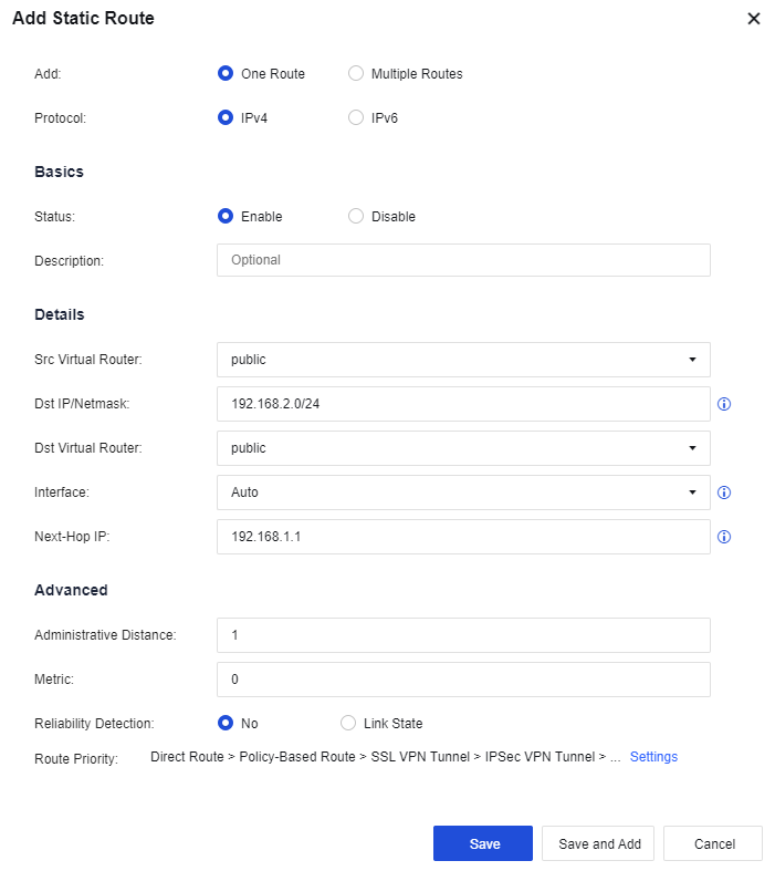
- Configure routing. You need to configure a default route to 0.0.0.0/0.0.0.0 pointing to the pre-gateway 192.168.1.254. Meanwhile, in this case, as the LAN interface is connected to multiple network segments spanning three layers, you need to configure another static route containing each network segment to the layer 3 switch. Go to the Network > Route > Static Route page and click Add to add a static route. Specifically, configure the default routing Dst IP/Netmask as 0.0.0.0/0 and the Next-Hop IP as 192.168.1.254, and configure the backhaul routing Dst IP/Netmask as 192.168.2.0/24 and the Next-Hop IP as 192.168.1.1. See the figure below:

- Configure the application control policy. Assign the Internet access permissions to LAN users. On the Policies > Access Control > Application Control Policy page, add an application control policy and assign the LAN-WAN data access permissions. Then, select the custom downlink zone as the Src Zone, the custom LAN address as Src Address, the custom uplink zone as Dst Zone, All in Dst Address, any in Services, and All in Applications.

- After completing the basic configuration, connect the device to the network, the eth2 interface to the preceding router, and the eth3 interface to the layer 3 LAN switch.
Deployment Case of Trunk Interface in Transparent Mode
The users’ network topology is shown in the figure below.
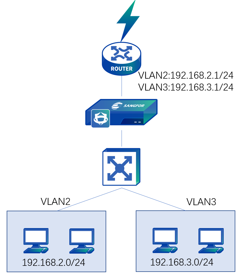
The device is deployed in transparent mode. The VLAN is configured for the LAN switch, but the routing function is disabled. The preceding router serves as the gateway of each VLAN. The LAN segments include 192.168.2.0/255.255.255.0 and 192.168.3.0/255.255.255.0, belonging to VLAN2 and VLAN3. The TRUNK protocol works between the switch and the router.
-
You need to log in to the device through the default IP address of the management interface (ETH0). The default IP address of the management interface is 10.251.251.251/24. You need to configure an IP address in the same network segment on the computer and log in to the device via https://10.251.251.251.
-
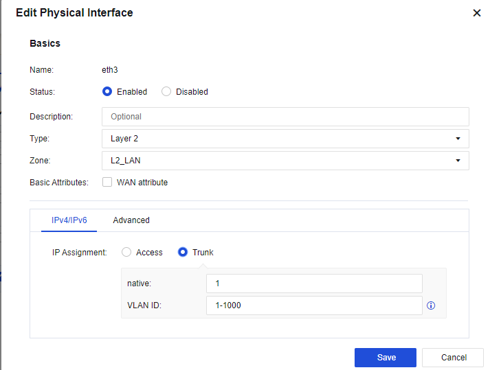
On the Network > Interfaces > Physical Interface page, click the interface to be set as a WAN interface. Select eth2 as the uplink WAN interface, select the transparent type and the custom uplink zone, check the WAN attribute checkbox, and set IP Assignment to Trunk, as shown below:

- On the Network > Interfaces > Physical Interface page, click the interface to be set as a LAN interface. Select eth3 as the downlink LAN interface, select Layer 2 for Type and the custom downlink zone, and set IP Assignment to Trunk, as shown below.
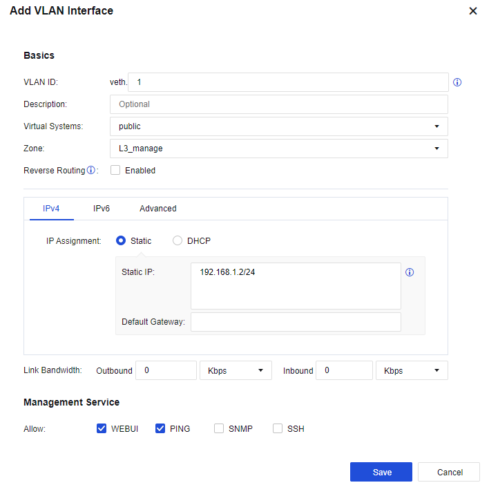
- Configure the management interface. On the Network > Interfaces > VLAN Interface, configure the logic interface of the VLAN interface as the management interface, set the VLAN ID field to 2, and assign a management IP address 192.168.2.2/24. See the figure below.
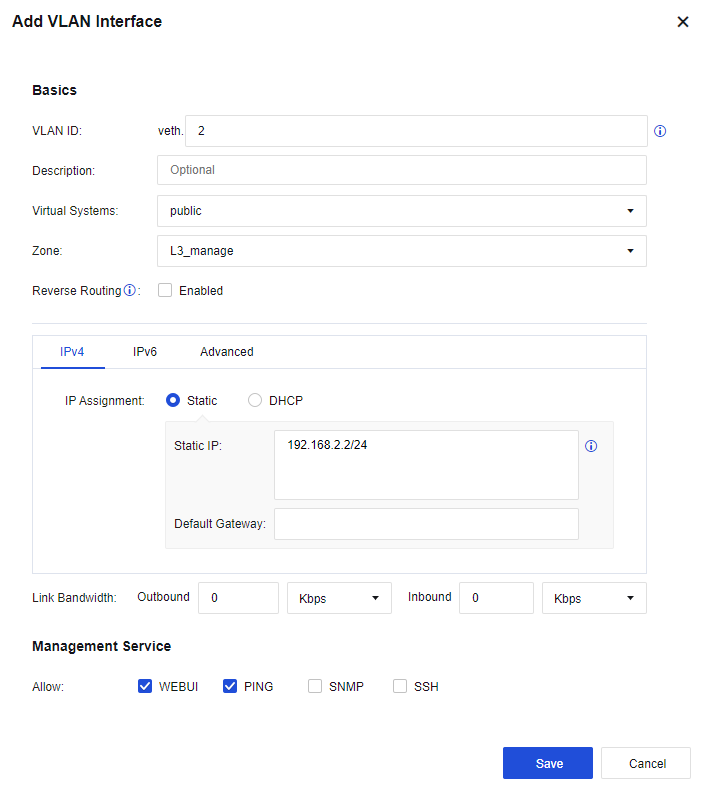
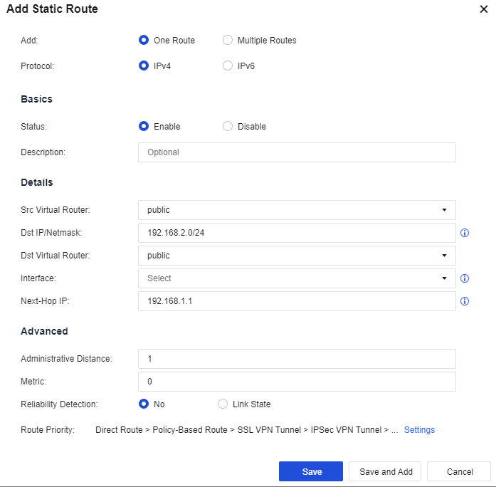
- Configure routing. You need to configure a default route to 0.0.0.0/0.0.0.0, pointing to the next-hop192.168.2.1 that belongs to the same network segment as the management IP address. Then, go to the Network > Route > Static Route page and click Add to add a static route. Specifically, configure the default routing Dst IP/Netmask as 0.0.0.0/0 and the Next-Hop IP as 192.168.2.1, as shown below.

- Configure the application control policy. Assign the Internet access permissions to LAN users. On the Policies > Access Control > Application Control Policy page, add an application control policy and assign the LAN-WAN data access permissions. Then, select the custom downlink zone as the Src Zone, the custom LAN address as Src Address, the custom uplink zone as Dst Zone, All for Dst Address, any for Services, and All for Applications.

- After completing the basic configuration, connect the device to the network, the eth2 interface to the preceding router, and the eth3 interface to the two-layer LAN switch.
Virtual Wire Mode
Virtual Wire deployment is similar to transparent deployment. The differences lie in:
The interface is also a layer 2 interface, but it is defined as a virtual cable interface:
-
The virtual network interfaces must be in pairs. When forwarding data, it does not need to check the MAC table and directly forwards it from the interface paired with the virtual network cable.
-
The forwarding performance of the Virtual Wire is higher than that of the Layer 2 interface, so deploying the virtual wire interface in a general network bridge environment is recommended.
-
The deployment of virtual network cables has occupied two interfaces. Hence, to connect a management device, you should select another interface.
Deployment Case of Virtual WireMode
The network environment of an enterprise is shown below.
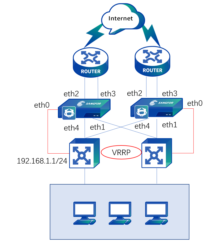
LAN has two layer 3 switch and two routers for load balancing. This enterprise wants to deploy the Network Secure device transparently on the environment but does not want to change the original Internet access mode. In this case, two-layer isolation must be provided between eth4 & eth2 networking interfaces and eth1 & eth3 networking interfaces. In other words, the data transmitted to eth4 must be forwarded from eth2, and that transmitted to eth1 must be forwarded from eth3, which can be realized through configuring a virtual cable interface.
The deployment methods of the two Network Secure devices are the same. We have illustrated the steps by taking one as an example.
-
Log in to the device through the default IP address of the management interface (ETH0). The default IP address of the management interface is 10.251.251.251/24. You need to configure an IP address in the same network segment on the computer and log in to the device via .
-
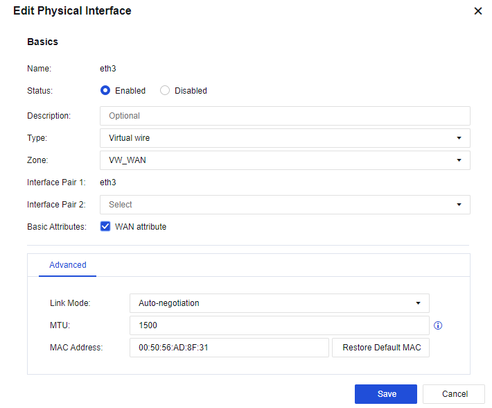
On the Network > Interfaces > Physical Interface page, click the interface to be set as a WAN interface. Select eth2 as the uplink WAN interface and select the Virtual Wire type and the custom uplink zone, as shown below:
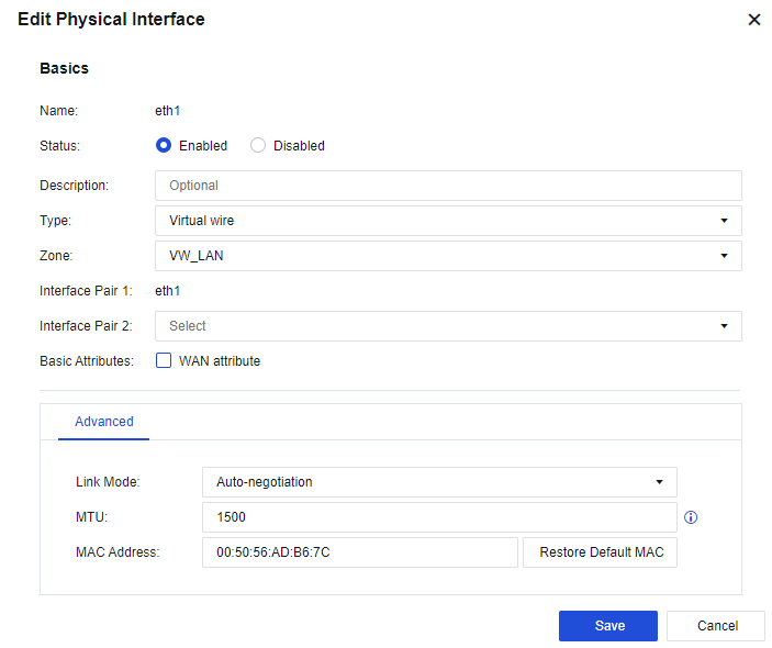
- On the Network > Interfaces > Physical Interface page, click an interface and set it as a LAN interface. Select eth4 as the downlink LAN interface, select the Virtual Wire type and the custom downlink zone, and set eth2, as defined in Step 1 for Interface Pair 2, as shown below.
-
Configure eth1 and eth3 interfaces according to the method described in steps 2 and 3.
-
Configure the management interface. On the Network > Interfaces > Physical Interface page, select eth0 as the management interface. Do not modify the default IP address of eth0 10.251.251.251/24. Add an IP address belonging to the same network segment as the LAN switch as the management IP address so that the LAN administrator can conveniently manage the device.
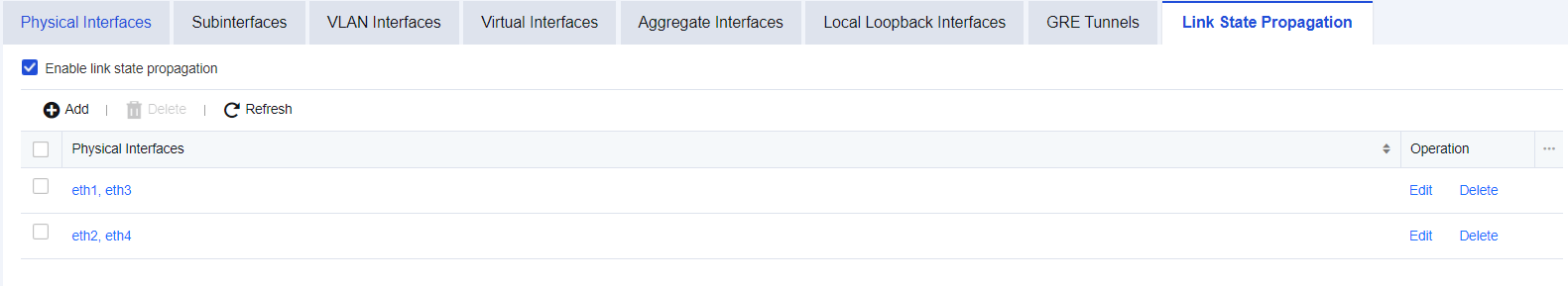
- In this case, enable interface correlation on Network > Interfaces > Link State Propagation page to realize active and standby switching between LAN switches and routers. Check the Enable link state propagation on the page and select eth1 & eth3 and eth2 & eth4 for interface correlation, as shown below:
- Configure routing. You need to configure a default route to 0.0.0.0/0.0.0.0, pointing to the LAN switch 192.168.1.1. Then, go to the Network > Route > Static Route page and click Add to add a static route. Specifically, configure the default routing Dst IP/Netmask as 0.0.0.0/0 and the Next-Hop IP as 192.168.1.1. See the figure below.

- Configure the application control policy. Assign the Internet access permissions to LAN users. On the Policies > Access Control > Application Control Policy page, add an application control policy, and assign the LAN-WAN data access permissions. Then, on the displayed page, select the custom downlink zone as the Src Zone, the custom LAN address as Src Address, the custom uplink zone as Dst Zone, All in Dst Address, any in Services, and All in Applications.
- After completing the basic configuration, connect the device to the network, eth2 and eth3 interfaces to the preceding router, and eth1 and eth4 interfaces to the two-layer 3 LAN switches.
Mirror Mode
In Mirror mode, there is no need to change a user’s network environment at all, and it can avoid the risk of interrupting the user’s network by the device while providing protection. It is used to connect the device to the mirror port of the switch or to the HUB to ensure that data from external users accessing the server passes through the switch or HUB. When setting the mirror port, it is necessary to mirror the upstream and downstream data simultaneously to protect the server.
Deployment Case of Mirror Mode
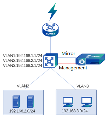
A user’s network topology is shown below. The Network Secure device is deployed in the mirror mode with the LAN connected to a layer 3 switch. The user’s network segment is 192.168.3.0/24, and the server network segment is 192.168.2.0/24. The customer wants Network Secure to perform intrusion prevention and Web app protection on the server and prevent the leakage of sensitive data.
-
Log in to the device through the default IP address of the management interface (ETH0). The default IP address of the management interface is 10.251.251.251/24. You need to configure an IP address in the same network segment on the computer and log in to the device via https://10.251.251.251.
-
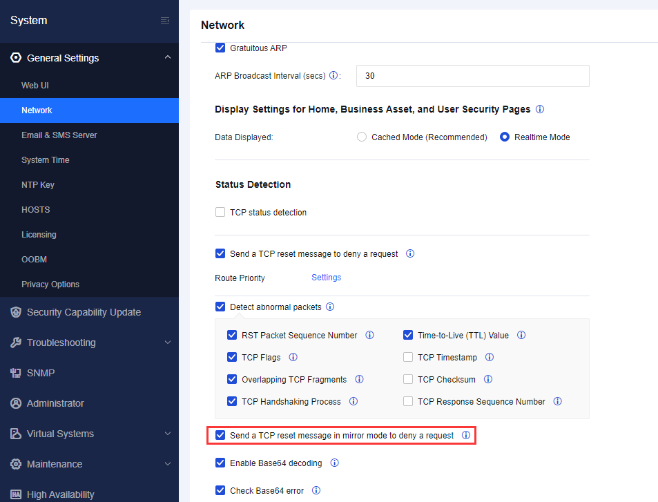
Check Send TCP reset message in mirror mode to deny a request on the System > General Settings > Network, and send TCP RESET message through the management interface for control in the mirror mode.
- Configure a management interface. In mirror deployment, the device blocks connections through the management interface.
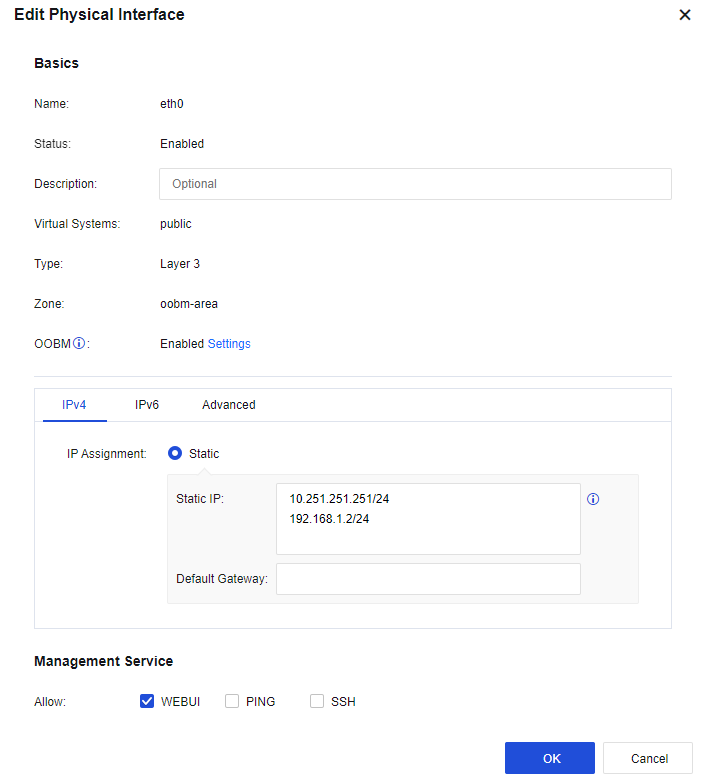
On the Network > Interfaces > Physical Interface page, select eth0 as the management interface. Do not modify the default IP address of eth0 10.251.251.251/24. Add an IP address belonging to the same network segment as that of the LAN switch as the management IP address. See the figure below:
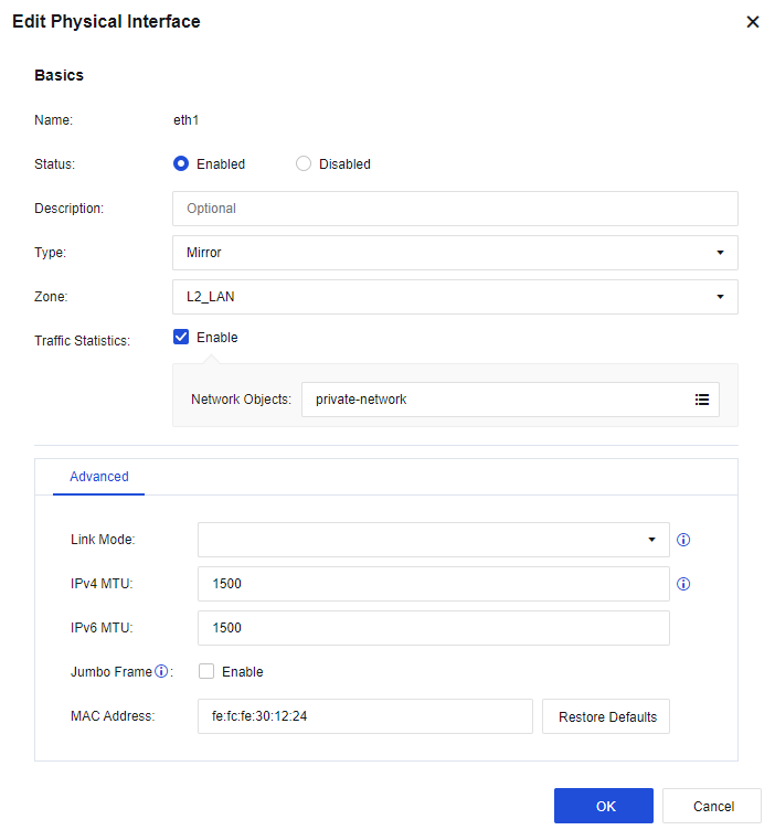
- Configure the mirror interface. On the Network > Interfaces > Zone > Physical Interface page, select eth1 as the mirror interface. Click eth1, then select Mirror for Type, select the custom LAN as Zone, check Enable for Traffic Statistics, and select the custom server network segment in Network Objects, as shown below.
- Configure a route: You need to configure a default route to 0.0.0.0/0.0.0.0, pointing to the LAN switch 192.168.1.1. Then, go to the Network > Route > Static Route page and click Add to add a static route. Specifically, configure the default routing Dst IP /Netmask as 0.0.0.0/0 and the Next-Hop IP as 192.168.1.1. See the figure below.

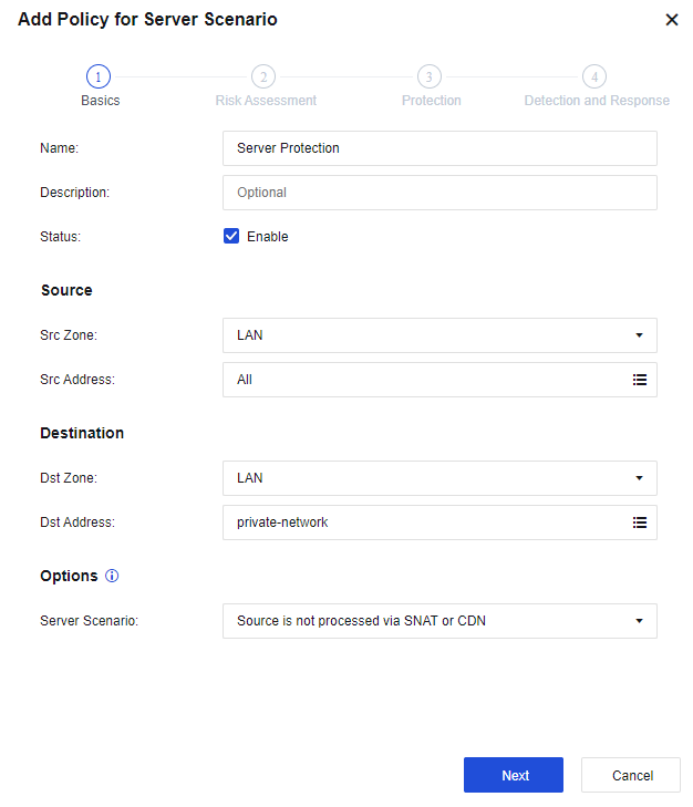
- Configure protection rules: By taking the configuration of a service protection policy as an example, the following content is about setting a service protection policy in the mirror mode. On the Policies > Security Policy > Policy for Server Scenario page, add a new service protection policy.
In the Mirror mode, select the object to be protected and defended in Zone under both Source and Destination. Select the server segment to be covered in Network Object under Destination, as shown below.
- After completing the basic configuration, connect the device to the network, the eth1 interface to the mirror interface of the layer 3 switch, and the eth0 interface to the interface within the scope of VLAN1 of the layer 3 LAN switch.
Notice:
Mirror deployment only supports these functions: APT (Botnet), PVS (real-time vulnerability analysis), WAF (Web app protection), vulnerability attack protection, DLP (data leakage prevention), and website tamper-proofing functions (client protection). When blocking is unnecessary, do not check the Send TCP Reset message in mirror mode to deny request function.
Mix Mode
Mix deployment refers to the Layer 3 interfaces, Layer 2 interfaces, and virtual wire interfaces that exist simultaneously on the Network Secure device. You can select the deployment mode depending on different customer demands.
Deployment Case of Mix Mode
An enterprise’s LAN has many server clusters for users to access through the Internet, with the IP address(es) of the Internet assigned to each server. This enterprise wants to deploy the Network Secure device on the Internet port so that users can directly access server clusters through the Internet IP address and does not want to publish the server through port mapping. Also, it hopes the Network Secure device serves as a LAN proxy to access the Internet. The network topology is shown in the following figure.
In this case, the users need to access the server through the server’s Internet IP address. It is required to set the Network Secure device’s eht2 interface connected to the Internet and the eth1 interface connected to the server cluster on the LAN as the transparent access interface, belonging to the same VLAN. Set a VLAN interface and configure an Internet address for it. Set the eth3 interface connected to the LAN as the routing interface. When LAN users access the Internet, they can convert the source IP address to the Internet IP address of the VLAN interface. By doing so, the users’ demand is met.
-
Log in to the device through the default IP address of the management interface (ETH0). The default IP address of the management interface is 10.251.251.251/24. You need to configure an IP address in the same network segment on the computer and log in to the device via https://10.251.251.251.
-
Set the WAN interface. On the Network > Interfaces > Physical Interface page, select eth2 as the WAN interface. Click eth2, select the Layer 2 type, select the custom WAN in Zone, check the WAN attribute option, and set IP Assignment to Access 1, as shown below.
- Set the server zone interface. On the Network > Interfaces > Physical Interface page, select eth1 as the server zone interface. Click eth1, select the Layer 2 for Type, select the custom WAN in Zone, and set IP Assignment to Access 1, as shown below.
- Set the LAN interface. On the Network > Interfaces > Physical Interface page, select eth1 as the server zone interface. Click eth3, select the Layer 3 type, select the custom LAN in Zone, and enter the IP address 192.168.1.2/24, as shown below.

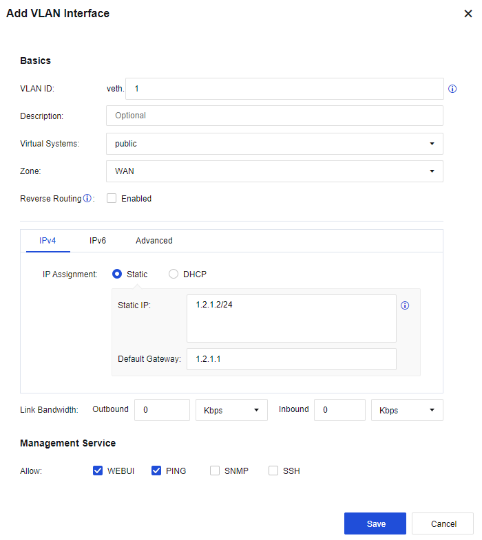
- Set the VLAN interface. On the Network > Interfaces > VLAN Interfaces page, click Add, set the VLAN ID field to 1, select the custom WAN in Zone, enter the IP address 1.2.1.2/24, and configure the next-hop gateway to 1.2.1.1, as shown below.
- Configure routing. You need to configure a default route to 0.0.0.0/0.0.0.0, pointing to the next hop 1.2.1.2. Meanwhile, as the LAN interface is connected to multiple network segments spanning three layers in this case, you need to configure a static route containing each network segment to the layer 3 switch. Go to the Network > Route > Static Route page and click Add to add a static route. Specifically, configure the default routing Dst IP/Netmask as 0.0.0.0/0 and the Next-Hop IP as 1.2.1.1, and configure the backhaul routing Dst IP/Netmask as 192.168.2.0/24 and the Next-Hop IP as 192.168.1.1. See the figure below.
- Configure the NAT policy. Go to Policies > NAT > IPv4 NAT. Click Add to configure the SNAT. Then, on the displayed page, select the custom LAN zone as the Src Zone, the custom LAN address as Src Address, the custom WAN zone as Dst Zone, All in Dst Address, any in Services, and Outbound Interface in Translate Src IP To respectively. See the figure below.
- Configure the application control policy. Assign the Internet access permissions to LAN users. Go to the Policies > Access Control > Application Control Policy page. Click Add. Assign the LAN-WAN data access permissions. Then, on the displayed page, select the custom LAN zone as the Src Zone, the custom LAN address as Src Address, the WAN zone as Dst Zone, All in Dst Address, any in Services, and All in Applications. See the figure below.
- Configure the application control policy. Allow all zones to access servers. Select any in the Src Zone, All in the Src Address, the server zone in the Dst Zone, and the custom server in the Dst Address. Services can be configured based on actual needs, such as HTTP. See the figure below.
- After the above steps, connect the device’s eth2 interface to the WAN line, eth1 interface to the server zone, and eth3 interface to the LAN switch.
Home
Record and display the device status, business asset security, user security, risk warning, etc., to visually control users’ access behaviors, as shown below.
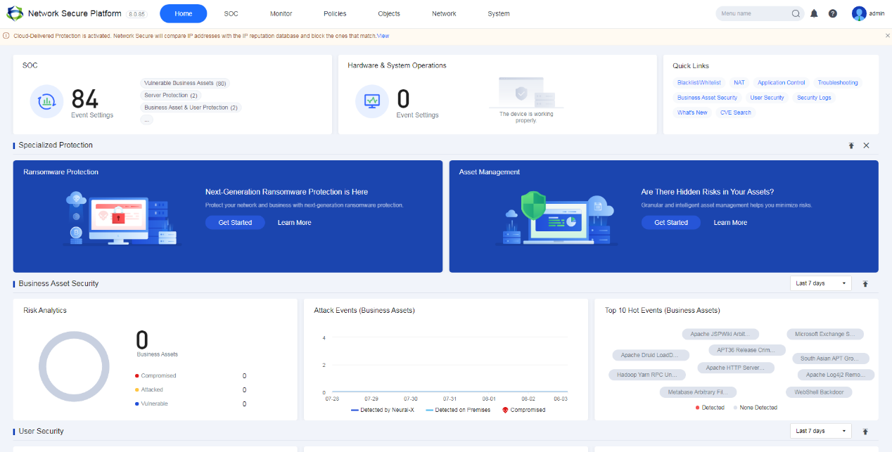
Security Operation Center (SOC)
SOC displays TOP3 to-do events and that the Network Secure device continuously evaluates customers’ security status from four aspects: Assess Risk, Protect, Monitor/Analysis, and Pending Issues. You can click the SOC icon to go to the SOC page.

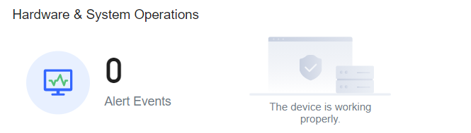
Hardware & System Operations
Hardware & System Operations mainly displays the information from four aspects: hardware and system operation alerts, rule database and license validity, system’s direct connection risk, and log compliance alerts. You can click the Hardware & System Operations icon to go to the Hardware & System Operations page.
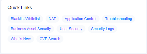
Quick Links
Quick Links allow you to quickly jump to related functional pages or use shortcut functions. It mainly includes blacklist and whitelist, network address translation (NAT), application control policy, troubleshooting, business asset security, user security, version introduction, and vulnerability CVE search.
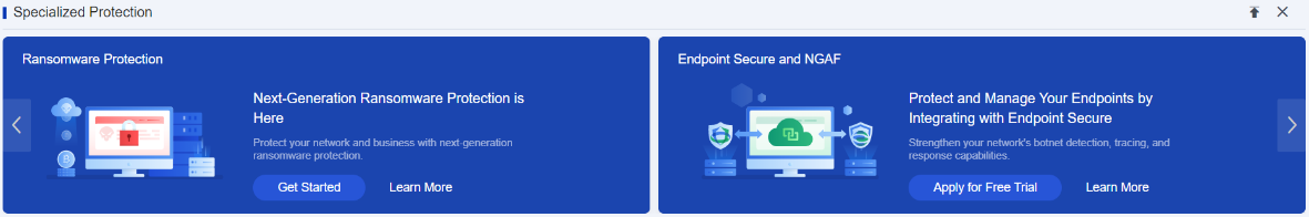
Specialized Protection
Specialized Protection shows the specialized protection functions for Network Secure, including ransomware protection, subscription service for all-in-one ES, and active trapping. You can click the button in the figure to open the configuration interface of the corresponding protection function.
Click  to stick this column to the top. Click
  to hide the Specialized Protection interface.
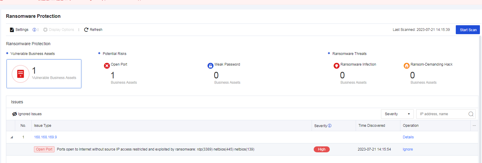
Ransomware Protection
Ransomware Protection displays ransomware protection data of Network Secure. You can click it to go to the corresponding protection configuration interface.
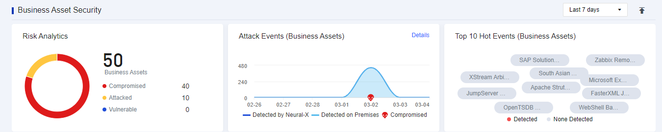
Business Asset Security
Business Asset Security enables you to quickly master the overall security of the business assets (security status distribution, vulnerability risk distribution, attack event trend, and TOP 10 real-time hot events across the network). See the figure below.
Click  to stick this column at the top.
Click the drop-down box. You can filter the information of a specific period by selecting the Last 7 days, the Last 2 days, and Today.
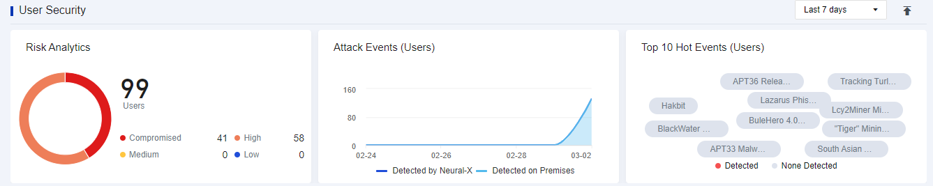
User Security
User Security enables you to quickly master the overall security of users (including the user security status distribution, attack trend distribution, and TOP 10 real-time hot events across the network). See the figure below.
Click  to stick this column to the top.
Click the drop-down box. You can filter the information of a specific period by selecting the Last 7 days, the Last 2 days, and Today.
Device Status
Device Status mainly displays the basic information of device status, system status, interface status, security capability, and product correlation.
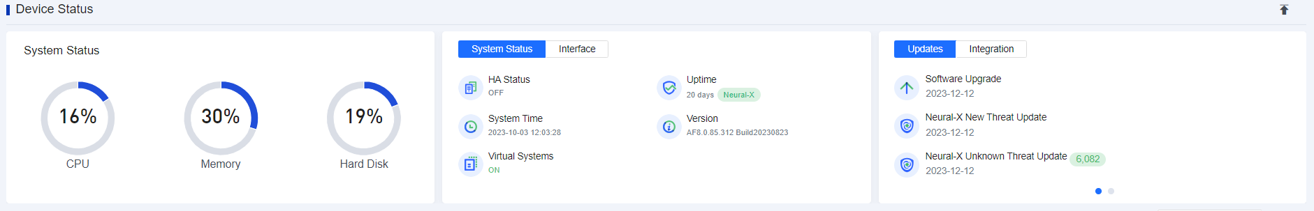
Device Status: Displays the CPU, memory, and hard disk usage of the device to check whether the device runs in normal conditions.
System Status: Displays the HA Status, Uptime, System Time, Virtual Systems, and device’s version.
Interface: Displays the current interface status. Green indicates that the interface is UP, and gray is DOWN.
Updates: Displays whether the rule database of the device is enabled and its expiration time.
Integration: Displays the protection function by correlating with the ES client. Click details to go to the Endpoint and Network Secure Protection module.
Click  to stick this column to the top.
Network Operations
Network Operations displays the overall status of your network, including four parts, i.e., concurrent sessions, new sessions, interface throughput trend, and real-time top apps by traffic.
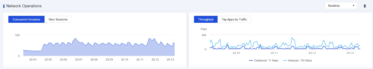
Click  to stick this column to the top.
Click the drop-down box. You can filter the information of a specific period by selecting the Last 7 days, the Last 2 days, and Today.
SOC
Display the overall security status of the device, provide daily maintenance, manage operation security services, provide specialized protection, give early warning about hot events, manage blacklists and whitelists, and correlate with the next-generation security system. It has many functional modules, including SOC, business asset security, user security, specialized protection, hot event warning, blacklist and whitelist, and next-generation security system.
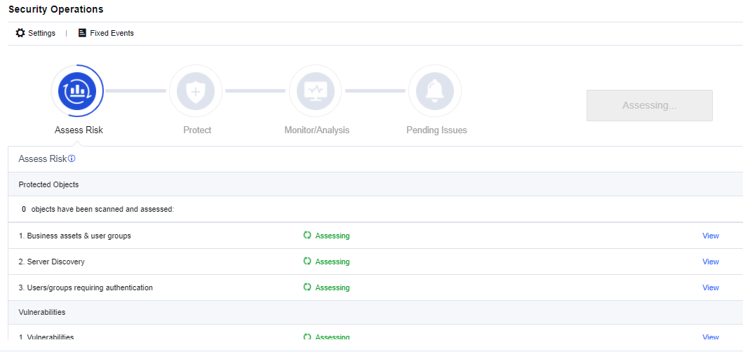
Security Operations
The SOC can assess overall risks, including the risks of the device, users, and business assets, and provide the event disposal guide, including four functional modules, i.e., risk assessment, dynamic protection, monitoring and analysis, and to-do events.
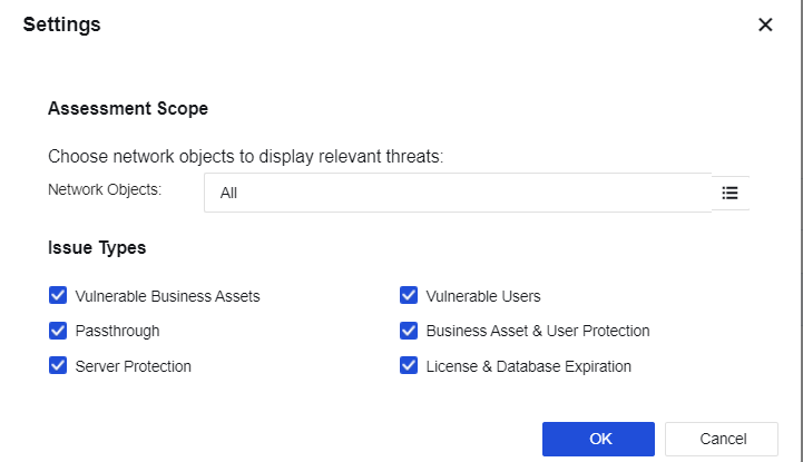
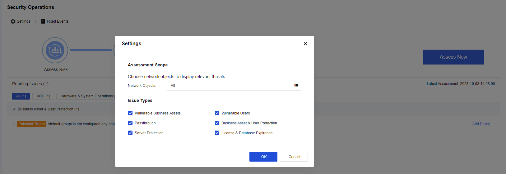
Click Settings. You can set the scope and options of the detection, as shown below.
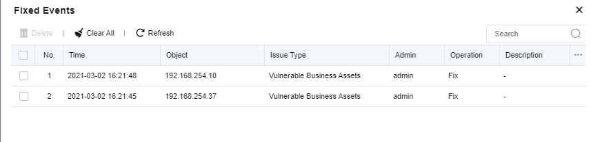
Click Fixed Events. The system will display the time, object, issue type, admin, operation, description, etc. You can search for the processing records, as shown below.
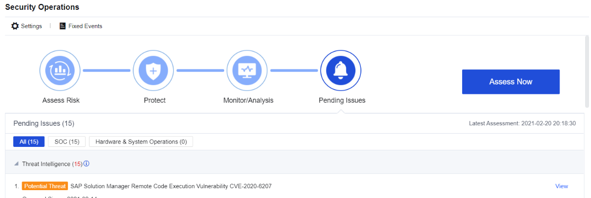
Click Assess Now. The system will perform four detection processes, i.e., Assess Risk, Protect, Monitor/Analysis, and Pending Issues, as shown below.
Click View. The system will jump to the corresponding functional module.
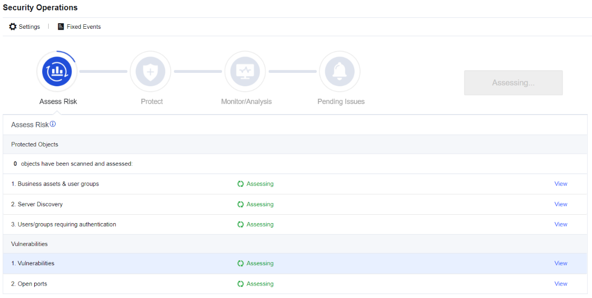
Assess Risk
Assess Risk mainly includes automatic assessment and manual assessment:
Automatic assessment
After being mounted on the rack for some time, once intrusion prevention, web app protection, or real-time vulnerability analysis is configured, the device will automatically perform risk assessments on the customer’s network status through active scanning every hour. It involves four aspects, i.e., risk assessment, dynamic protection, monitoring and analysis, and to-do events.
Manual assessment
To analyze and assess the client’s network status and risks in real-time, it is suggested to manually re-evaluate it to check if the cybersecurity meets the original requirements after resolving the security incident.
Protect
Network Secure protects against intrusions via vulnerabilities, Web apps, botnet, malware, virus, and emails. Cloud-based security analysis can also provide an all-around capability to defend businesses and users against attacks. See the figure below.
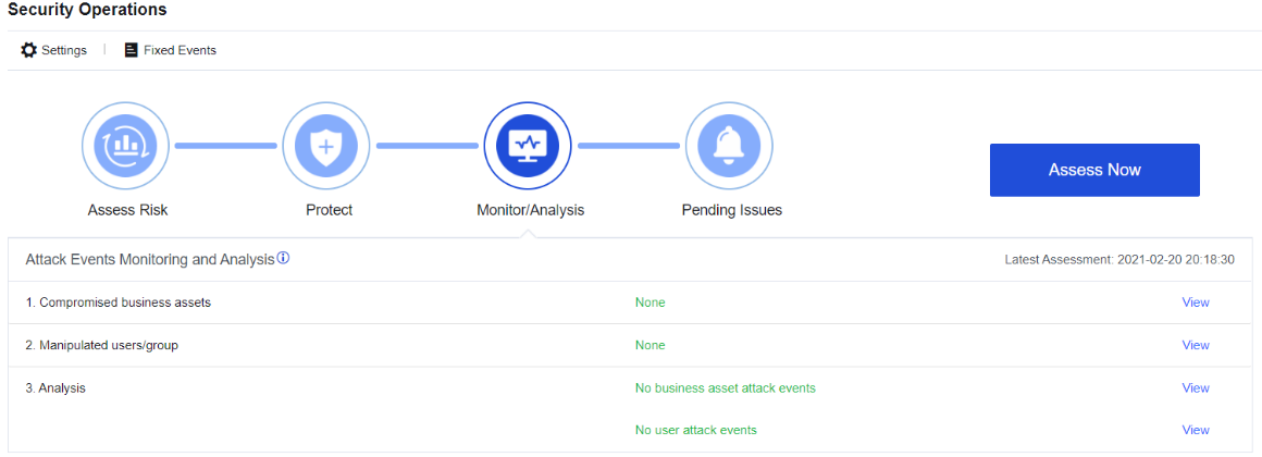
Monitor/Analysis
Network Secure monitors intrusions to the business system and the security status of end-users in real-time and constantly monitors the security status of businesses and users.
Network Secure provides an integrated data analysis platform to collect exceptional access, attack events, business vulnerabilities, and business/user security monitoring logs for in-depth analysis. It proposes solutions for identified security issues and constantly improves business security and user security. See the figure below.
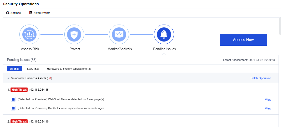
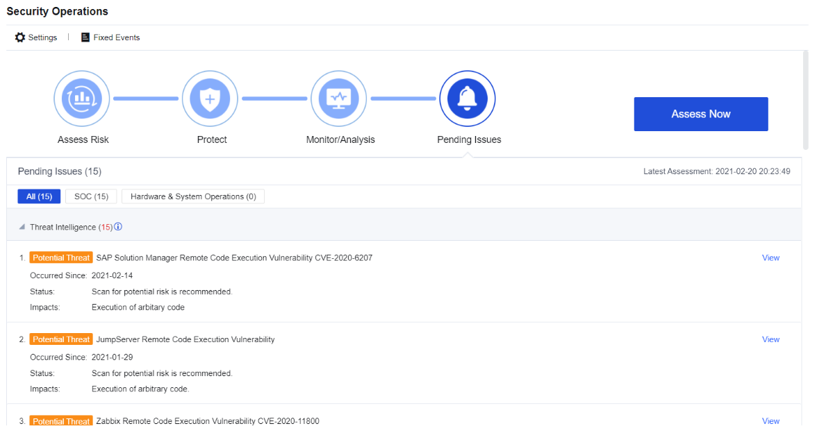
Pending Issues
Pending Issues enables you to view and deal with the risks in the network environment detected by the Network Secure device. You can set the scope and options of the detection and view the processing records, as shown below.
Configuration Case
The Network Secure deployed for an enterprise has been running stably. Now, this enterprise wants to view the risks of itself and its business assets detected by Network Secure to predict and identify the security risks of devices and business assets in time.
Configuration Steps:
- Click Settings to set the assessment scope, as shown below.
- Click Access Now to assess the set assessment scope, as shown below.
- After completing the assessment, view the assessment results, as shown below.
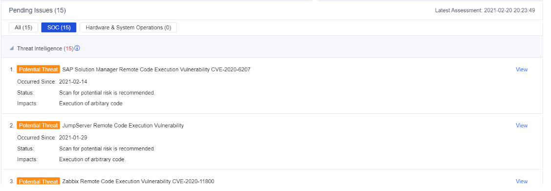
- Click SOC. You can query the early warning and disposal of matched hot events, the business and user intrusion risks so that you can quickly identify the businesses in the network having high risks and problems that need to be solved in time, as shown below.
- If an event has been processed or is a false positive, you can click Mark as fixed, and then you will not see the corresponding alarm later. Additionally, you can view the fixed events in the processing records, as shown below.
- Click Hardware & System Operations. You can view the problems existing in the system (such as License & Database Expiration), as shown below.
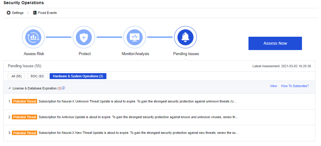
- You can fix the identified risks accordingly. For example, if the license is about to expire, you need to apply for a new license in time to prevent the rule database from not being updated.
IoT Security
IoT Security is used for implementing network-based management of trusted assets and continuous monitoring of the risks of connected assets. You can view the status and IP address of devices connected to the internal network. The IoT Security menu consists of Assets and Asset Discovery.
Note:
IoT Security is only available if the Network Secure has 4GB and above RAM.
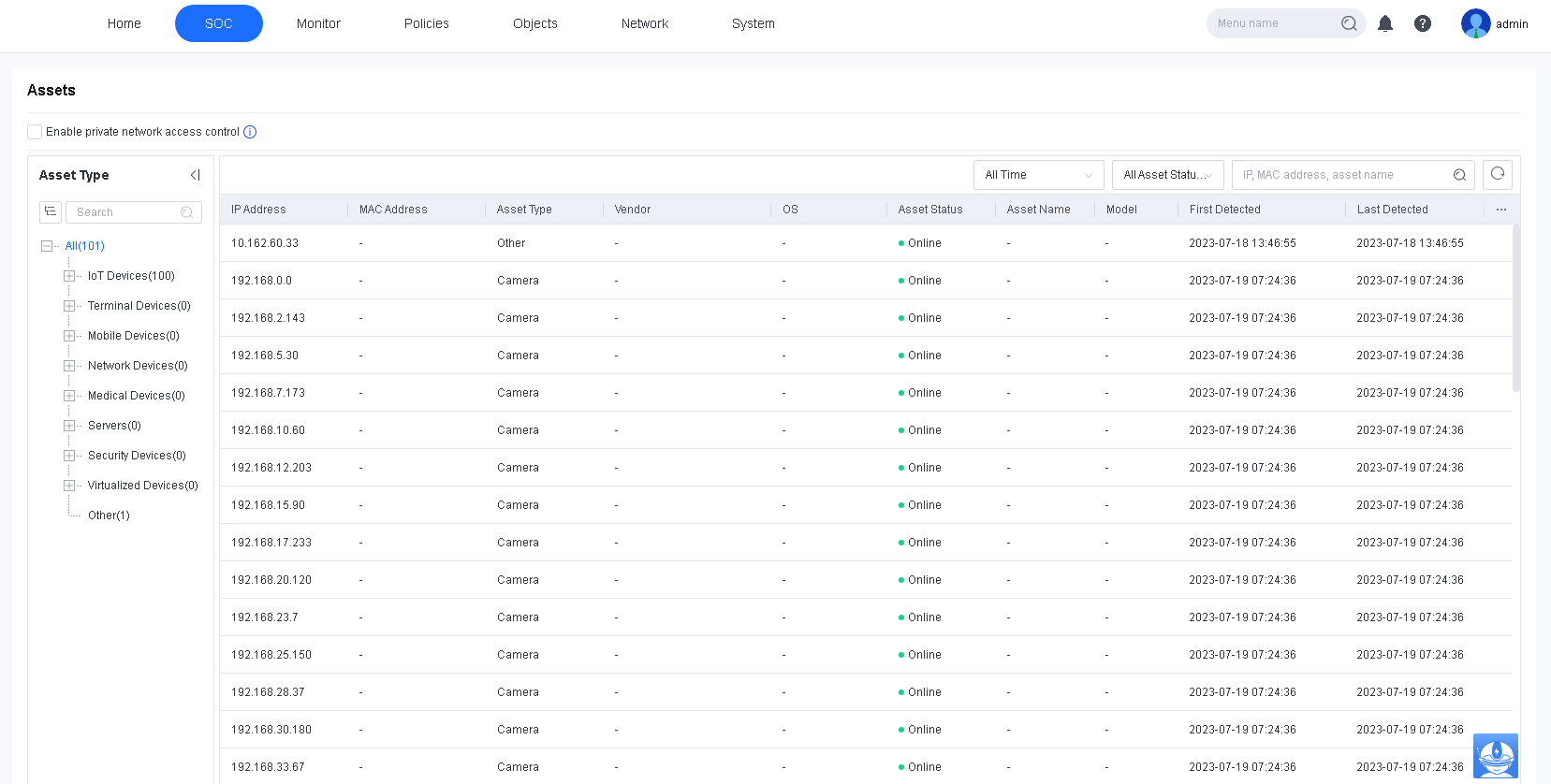
Assets
Assets displays IoT devices, terminal devices, PCs, mobile devices, network devices, medical devices, shared devices, and other custom assets. IoT devices include cameras, access control systems, printers, 3D printers, security devices, smart TVs, and enterprise IoT devices.
After you configure an internal network segment in Asset Discovery, the identified assets are displayed on the Assets page, as shown in the following figure.

Enable private network access control: If enabled, assets that are not reviewed cannot access the private network. When the Network Secure device is deployed in mirror mode, this feature takes effect only after you enable the Send a TCP reset message in mirror mode to deny a request option in System > General Settings > Network.
Asset Discovery
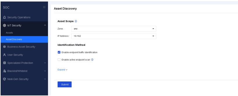
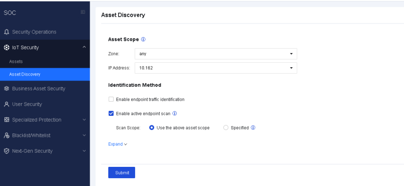
Asset Discovery is used for identifying assets to obtain their IP addresses, vendors, types, and other information. The obtained asset information is displayed on the Assets page. Asset Scope defines the scope for asset discovery. When Enable endpoint traffic identification is checked, Network Secure passively discovers assets within the specified scope by identifying traffic. When Enable active endpoint scan is checked, Network Secure actively scans assets within the specified scope to obtain asset information by sending packets. Do not check the two options at the same time.
Endpoint Traffic Identification
In IoT Security > Asset Discovery, select a scope for Asset Scope and check Enable endpoint traffic identification, as shown in the following figure.
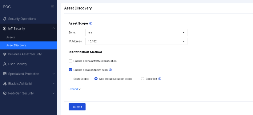
Active Endpoint Scan
In IoT Security > Asset Discovery, select a scope for Asset Scope and check Enable active endpoint scan. Identified assets are displayed on the Assets page after the scan is complete, as shown in the following figure.
Note:
Enable active endpoint scan is not recommended for medical scenarios because unexpected risks may arise in medical devices.
On the Advanced page, you can set asset scan intervals and inactive asset deletion policies, as shown in the following figure.
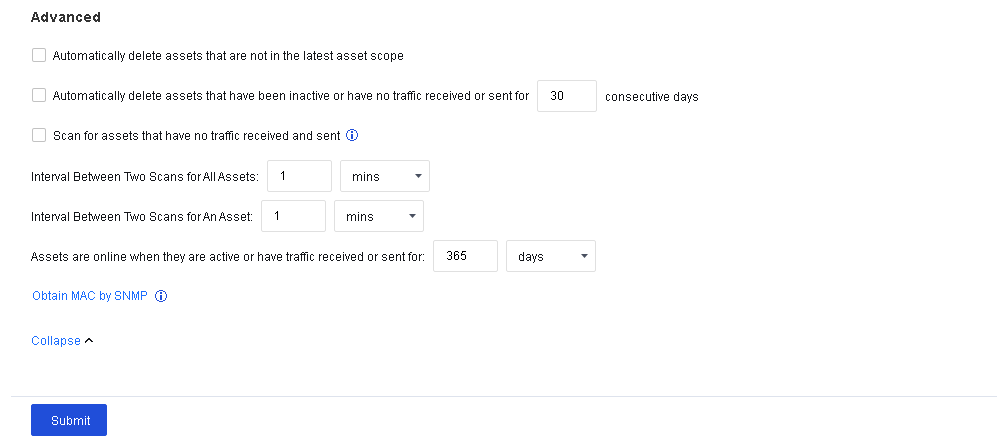
| Feature | Description |
|---|---|
| Automatically delete assets that are not in the latest asset scope | When checked, assets that are not in the IP range specified in Asset Scope are automatically deleted from Assets. |
| Automatically delete assets that have been inactive or have no traffic received or sent for 30 consecutive days | Assets that have been inactive or have no traffic received or sent for a specified number of consecutive days are automatically deleted. When integrated with Cyber Command, this feature is not displayed, and the automatic asset deletion time is determined by the time defined by Cyber Command for moving assets to inactive. |
| Scan for assets that have no traffic received and sent | The default concurrency for IP address scanning is 50. When this option is checked, the concurrency for IP address scanning by an individual CPU is 256, which significantly improves asset identification speed. |
| Interval between two scans for all assets | The interval between two consecutive scans of assets within the specified scan scope. |
| Interval between two scans for an asset | The interval between two consecutive scans of an asset. Assets identified in a scan have a cooldown period, during which the assets are not scanned until the cooldown period expires. |
| Assets are online when they are active or have traffic received or sent for a custom period of time | When checked, assets with received or sent traffic detected by Network Secure are displayed as online. |
| Obtain MAC by SNMP | For a cross-network segment asset scan, Network Secure can obtain the device’s IP address, type, and vendor, but not the MAC address. To obtain the MAC address, click Obtain MAC by SNMP. For details, see the Obtain MAC by SNMP section under Policies > Authentication > User Authentication > Authentication Options. |
Table 5: Features
Configuration Procedures
- Go to Security Operations > IoT security > Asset Discovery, check Enable active endpoint scan, and select Use the above asset scope for Scan Scope to reuse the zone and IP address specified in Asset Scope.
-
Click Submit and wait for the scan to complete.
-
After the scan is complete, go to the Assets page to view the identified assets.
Business Asset Security
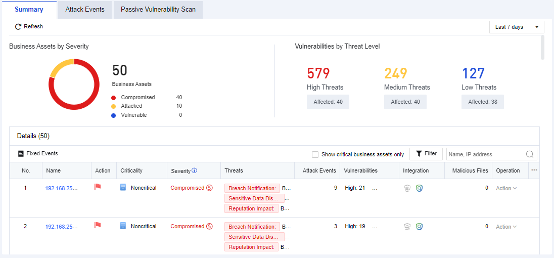
Business Asset Security shows the overall security status related to the business assets in the network, involving three functional modules, i.e., the summary of business asset risks, attack events, and real-time vulnerability analysis.
Summary of Business Asset Risks
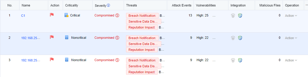
It shows the security status from the aspect of business assets. You can check whether the business assets have intrusion risks or view the potential risks, as shown below.

The description of risk levels is shown in the following table.
| Risk Level | Note |
|---|---|
| Compromised | Existing data prove that the server has been hacked, such as embedment of web shell, backlink, etc. |
| Attacked | There is no data to prove that the server is hacked, but it will save the evidence of an attack, including SQL injection, brute-force attack, web shell uploading, and other attack logs. |
| Data harvested | There is no data to prove that the server is hacked, but the evidence of collecting information will be recorded. |
| Vulnerable | There is no data to prove that the server is hacked, and there is no attack history, indicating the server has reconnaissance. |
Table 6: Description of risk levels
Key risks include compliance notification, sensitive data disclosure, reputation impact, and high/medium/low vulnerabilities. Vulnerability statistics are based on the real-time vulnerability analysis results.
You can only view the security status of core business assets by selecting Show Critical Business Assets. See the figure below.
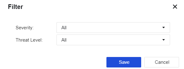
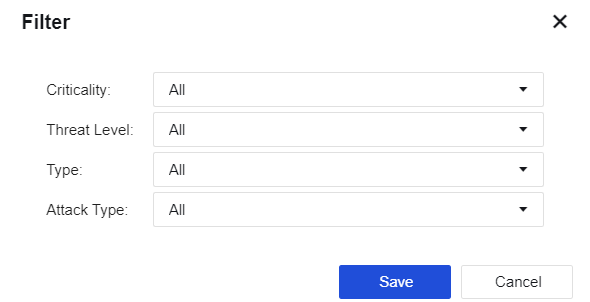
Click Filter. You can filter business assets by the Severity and Threat Level. See the figure below.
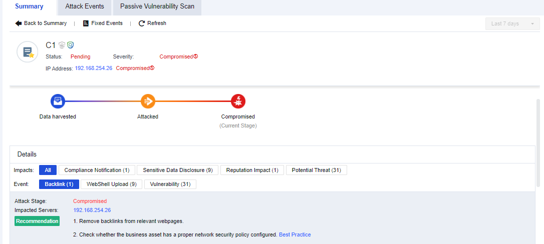
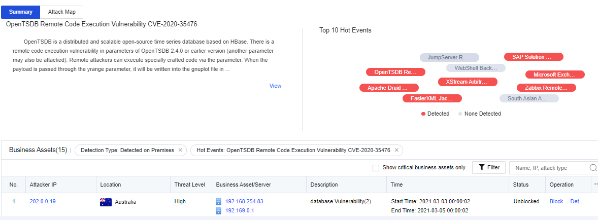
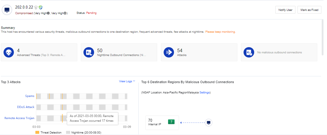
Click a business asset name. The following security details page will be displayed.

As shown in the above figure, the upper part is the summary of the business asset risks. Details include the current impacts on the business assets and the specific event types bringing such impacts (Webshell file access, Webshell backdoor, botnet, internal vulnerabilities, external attacks, etc.).
The risk level is Compromised. You can also see the impacted servers, recommendations, and proof.
Configuration Case
Network Secure has generated many business asset risk warnings in an enterprise, so admin must verify whether the mentioned business asset has such risks.
- Click Summary to check which business assets have risks. If they have compromised, you need to check the status of business assets first, as shown below.
- Click the business asset name to view the specific status of the business asset, as shown below.
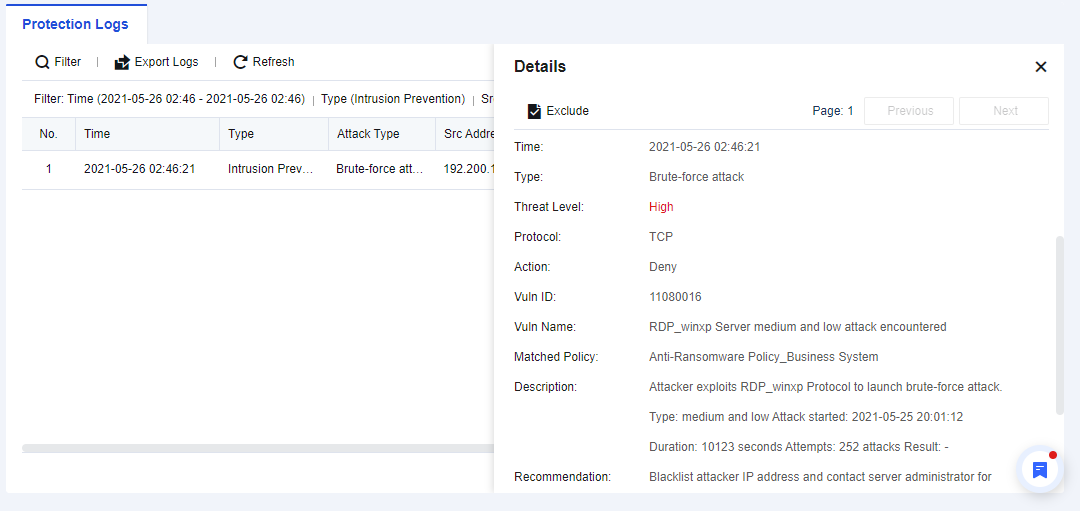
- View the corresponding events and click Log to analyze and judge the detection logs. Confirm whether the events are normal access, as shown below.
- If it is a false positive, you can add it as an exceptional case through the analysis and judgment based on logs to generate no alarm later.
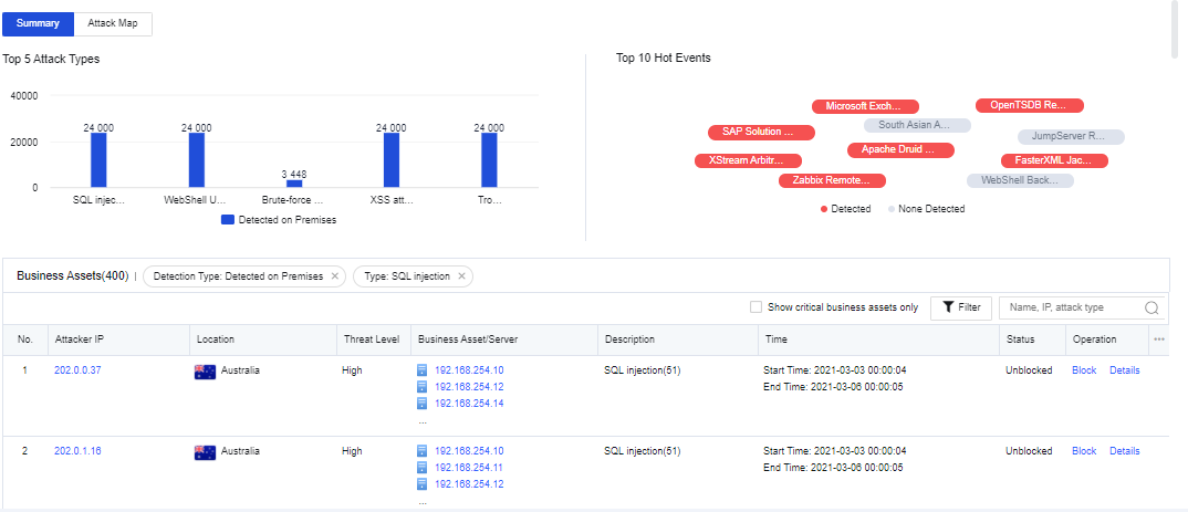
Summary of Attack Events
The Attack Events page displays the security data from the aspect of business asset security. You can see the TOP 5 attack types, as shown below.
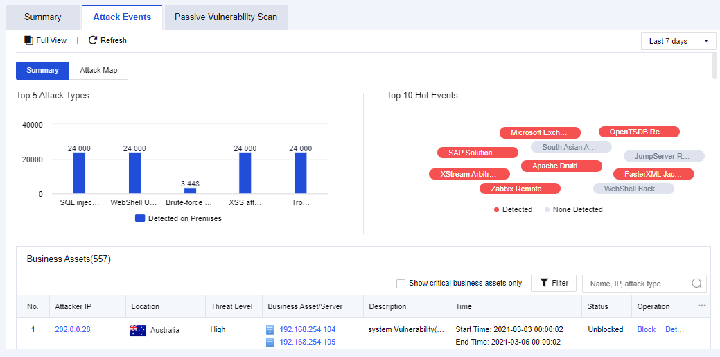
Attack Types
It mainly displays the TOP 5 attack types detected recently, as shown below.
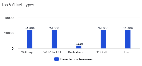
If you click the specific attack type, the logs related to this attack type will be displayed in the table.
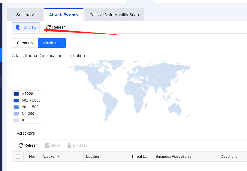
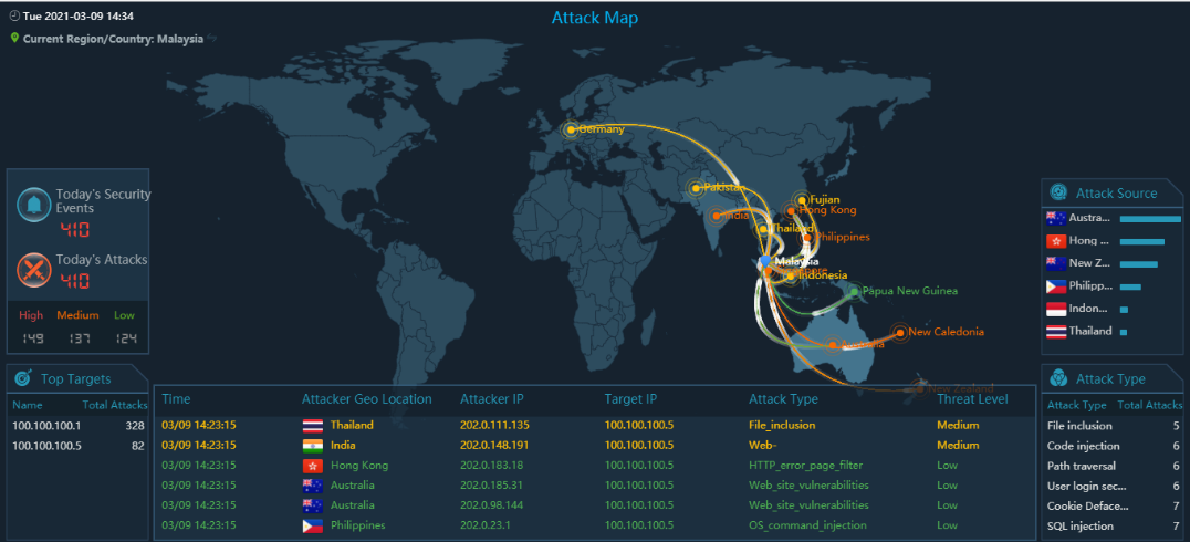
Attack Map
It displays that the Network Secure device detected the attacker’s IP today, in the last 2 days or 7 days.
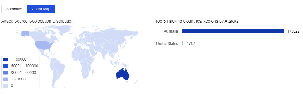
Click Full View. See the figure below.
Hot Events
It mainly refers to the Top 10 security events detected by the firewall across the network within a particular time. In these security events, if the attacking threat passes through the firewall and is detected by the firewall, the corresponding attack threat will be marked in red. If the traffic flowing through the firewall contains no attacking threat, the corresponding attack threat will be marked in gray.
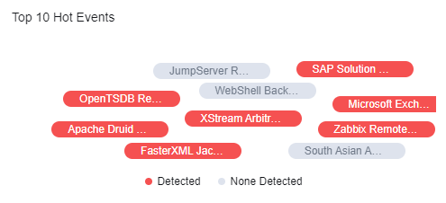
If you click a hot event, the logs of this event will be shown in the table. See the figure below.
Business Assets
It displays the latest attack events, as shown below.
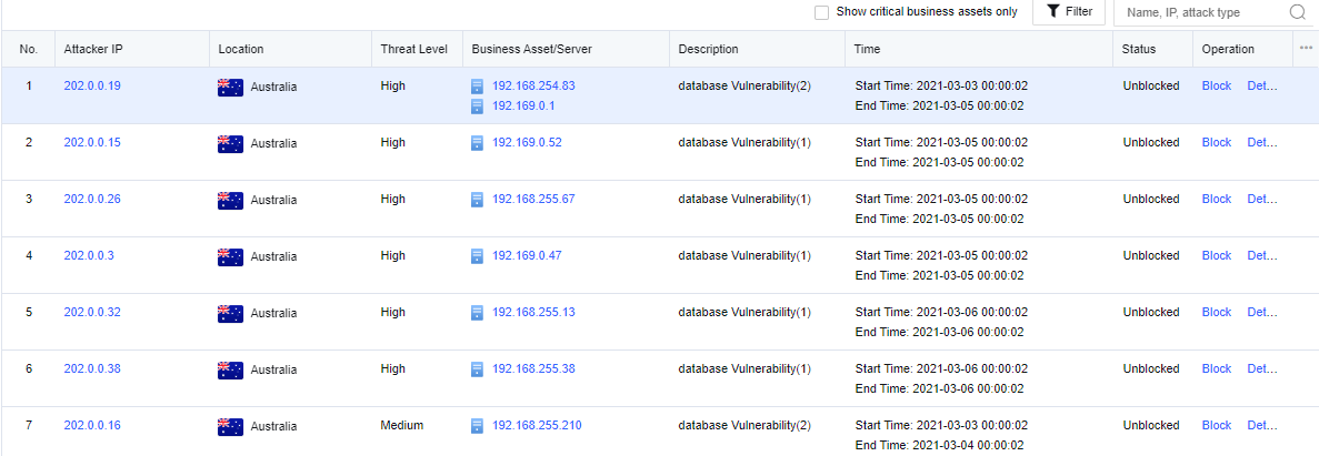
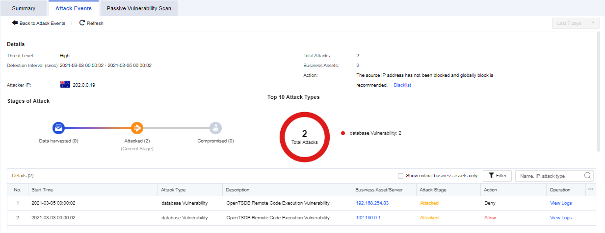
The displayed contents include the attacker’s IP, location, threat level, business asset/server impacted, event description, attack time, status, and operation.
Click an attacker’s IP. You can see the threats that this IP address poses on customers’ business assets (event details, attack chain, and TOP 10 attack types) and add this IP address to the blacklist for the correlated block. See the figure below.
You can view only the security status of core business assets by selecting Show critical business assets only.
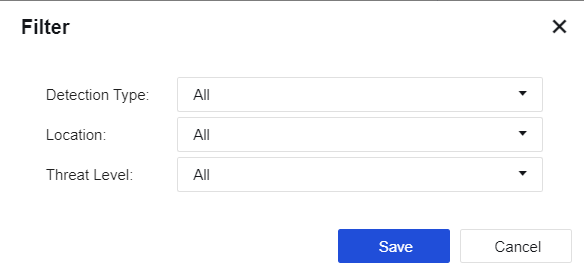
Click Filter. You can filter the attacks by the detection type, location, and threat level. See the figure below.
Passive Vulnerability Scan
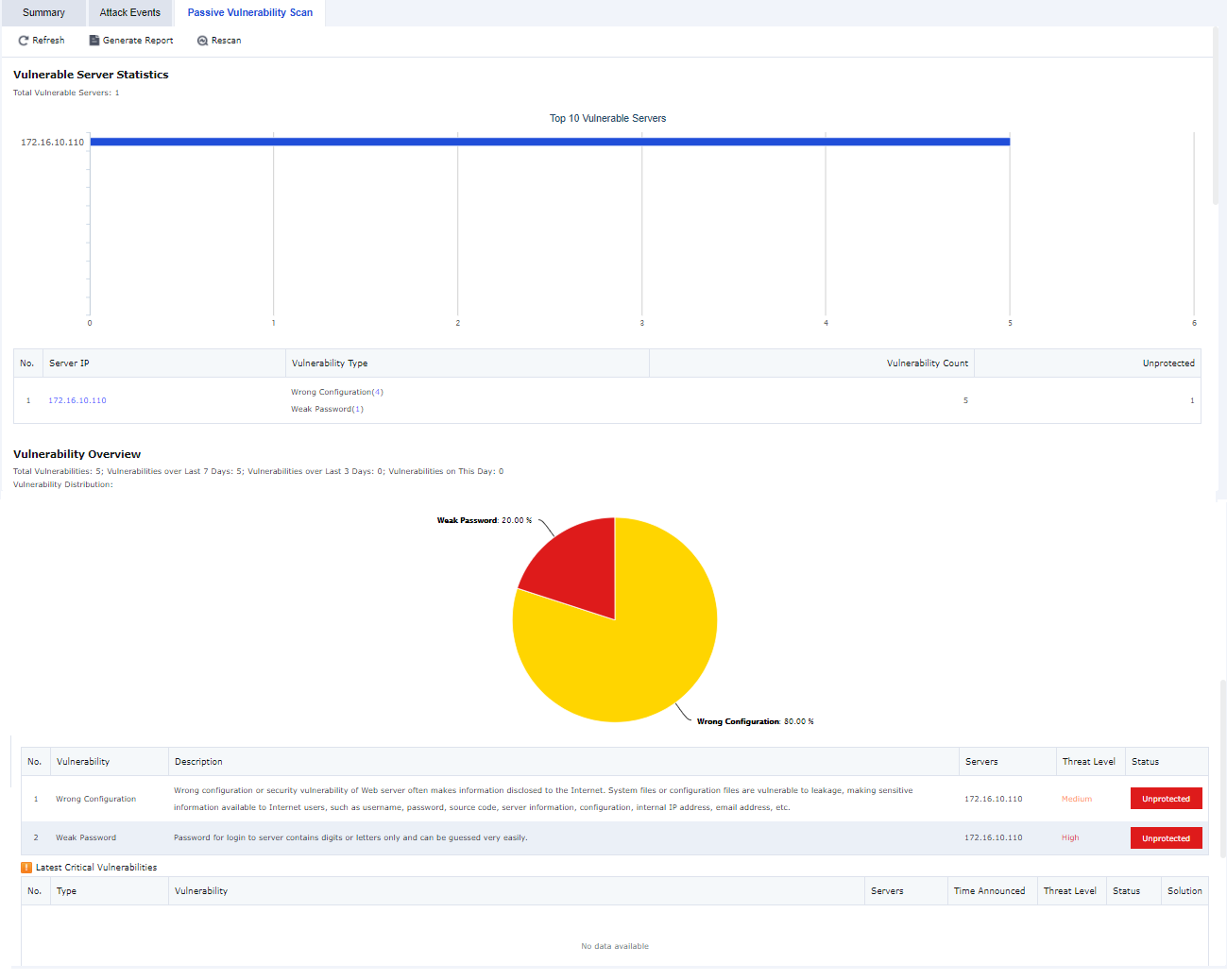
It lets you view the real-time information generated by the Nerwork Srcurity Policies (Policies > Network Security > Policies) module and the security vulnerability risks in the business assets.
The displayed contents include the target server information, vulnerability risk profile, list of the latest critical vulnerabilities, and details of risks recently identified.
This page only displays the summary of vulnerability risks. To view more details and the solutions, you can click Generate Report for more information.
User Security
It displays security status from the aspect of users to master the security status of users in the network, including two functional modules: summary of user risks and attack events of users.
Summary of User Risks
It displays the security status from the aspect of users, including the security status distribution and stage distribution. See the figure below.
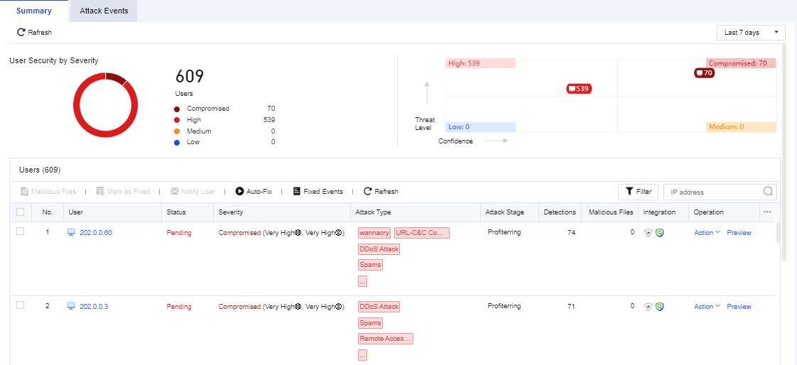
User Security by Severity displays the distribution of affected users.
Under User, it displays the latest attack events that users suffer. The contents include the user, severity, event status, attack stage, attack type, detections, integration, etc.
Click a user on the User list. The system will jump to the User Details page. Then, you can see user security details, attack stages, and summary. See the figure below.
You can view the security status of core business assets by selecting Show Critical Business Assets.
Click Filter. You can filter users based on their criticality, severity, status, and attack stage.
Attack Events
It displays user security from the aspect of the attack type. It can collect the user risks (whose traffic passes through Network Secure) identified by Network Secure based on hot events detected across the network. If hot events are matched, they will be marked in red; if no risk type is detected, they will be marked in gray.
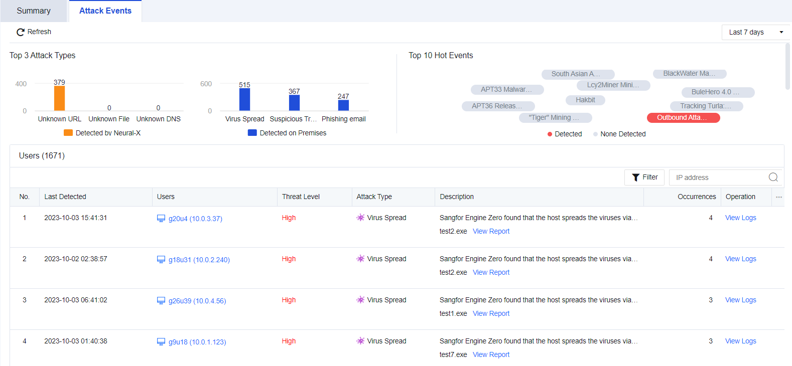
Top 3 Attack Types
It mainly displays the distribution of the Top 3 Attack Types. See the figure below.
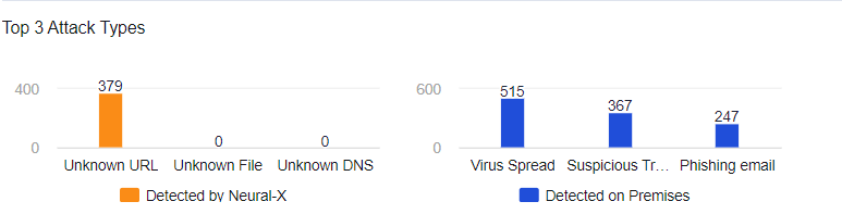
If you click the specific attack type of security event, the logs related to this attack type will be shown in the table.
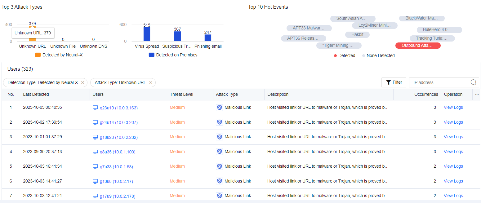
TOP 10 Hot Events
The top 10 real-time hot events across the network are ranked based on the current hot events. It will be analyzed in combination with the current attack logs of customers to find out whether hot events have attacked the customer’s LAN users. The red one indicates that the business assets have suffered from such hot events, while the gray one indicates that the same has not suffered from the hot events. See the figure below.
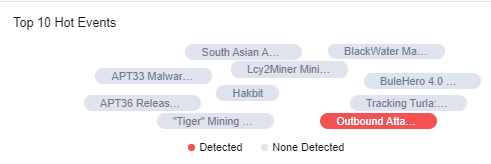
If you click a hot event, the logs of this event will be displayed in the table below.
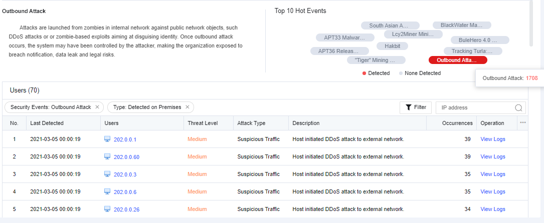
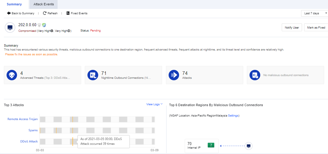
Affected Users
It displays the attack events in different periods, including today, the last 2 days, or the last 7 days.
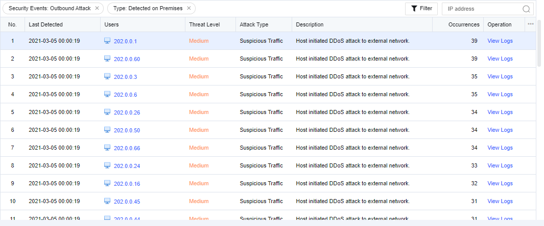
The contents include the last detected, users, threat level, attack type, description, occurrences, and operation.
Click on an affected user. You can view the details of the attack (attack time, attack type, attack description, etc.) on the user and add the attacker IP to the blacklist for the correlated block. See the figure below.
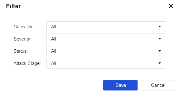
Click Filter. You can filter users based on the criticality, threat level, type, and attack type.
Specialized Protection
It displays the specialized protection functional modules for the device, which enables you to get the protection status of the modules and respond to them quickly.
The modules mentioned above include Asset Management, Ransomware Protection, IP Reputation, Account Protection, and Endpoint App Control.
Asset Management
Asset management is the core functional module of refined management and control. In the Report Center scenario, the active scan is mainly used to detect the online status of servers and the usage of ports, help users sort out the access relationship of business assets, reduce the open ports of policies, and streamline the ACL policy.
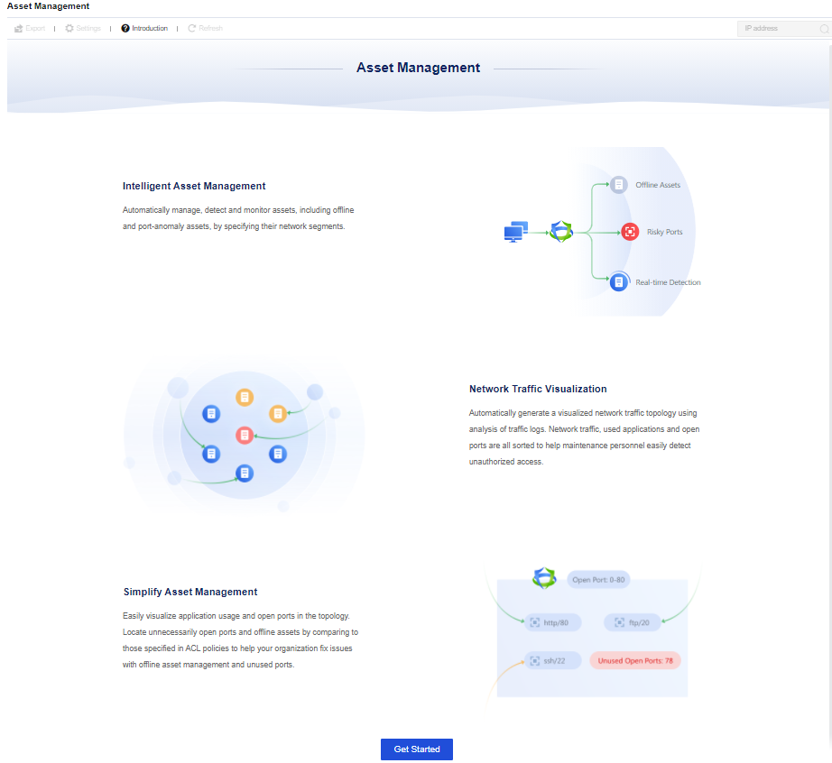
Click Get Started. The Settings page will pop out with the function description. See the figure below.
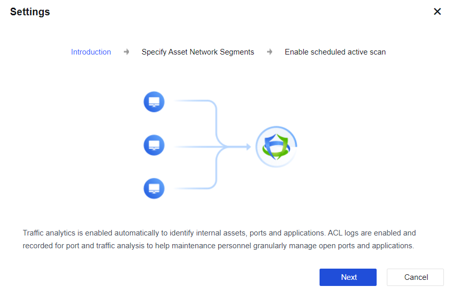
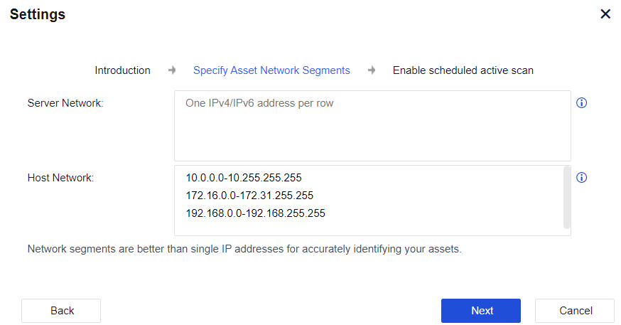
Click Next. Then, you can specify a single IPv4 or IPv6 address, range, and network segment of the server and host networks. For the active scan of asset management, the device will only scan the IP addresses filled in the field of the Server Network segment. That is, as long as IP addresses are filled in the Server Network segment, they will be identified as server assets, and these IP addresses will be actively scanned. Internet network segments that are not within the range of these two network segments or private network segments should be configured as accurately as possible. Otherwise, the scanning time will increase. See the figure below.
Click Next after setting. Go to the Enable scheduled active scan page. If the active scan is needed, check the Enable scheduled active scan and accept the Disclaimer checkbox. After this feature is selected, the device will periodically and actively scan the LAN server network segment to obtain the active status of the server and the usage of ports and applications. To change the scan time and scan port, click Scan Schedule next to the Scheduled Active Scan option to edit it.
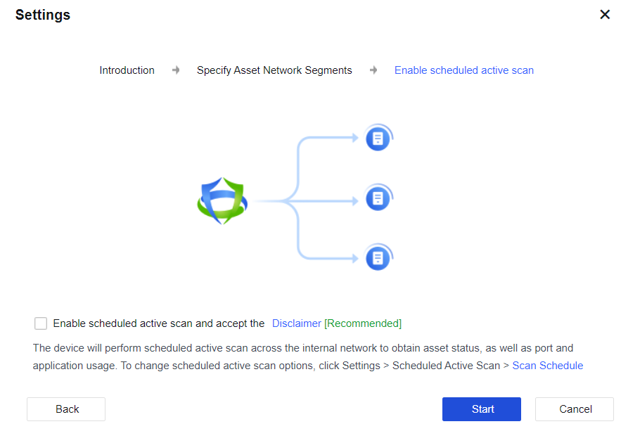
Click Start to complete the configuration.
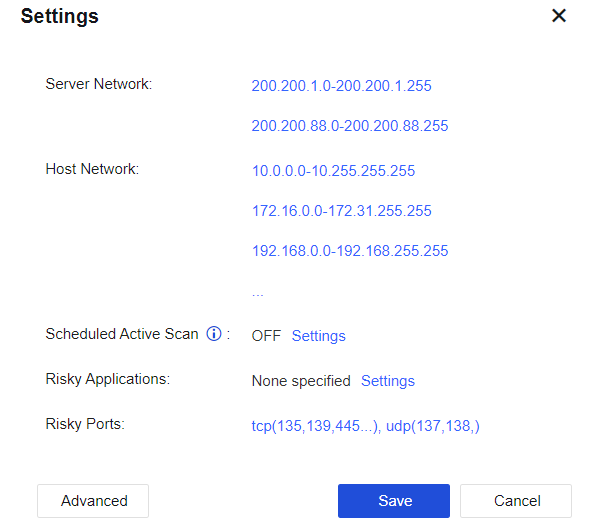
After the Asset Management functional module is enabled, click Settings on the Asset Management page to modify the configuration related to the active scan. See the figure below.
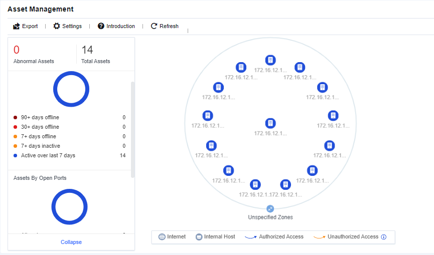
After completing asset management, you can see the online status of server assets, the usage status of server asset ports, and the topological diagram of the access relationship between assets. Administrators can manage and optimize business assets in combination with asset management results.
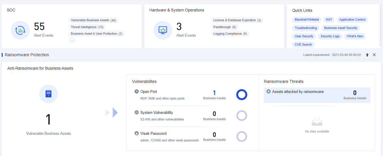
Ransomware Protection
Network Secure comprehensively protects against ransomware risks by generating policies for protected objects automatically, identifying ransomware risks comprehensively and visually, and providing remediation suggestions and ideas so administrators can deal with ransomware risk events.
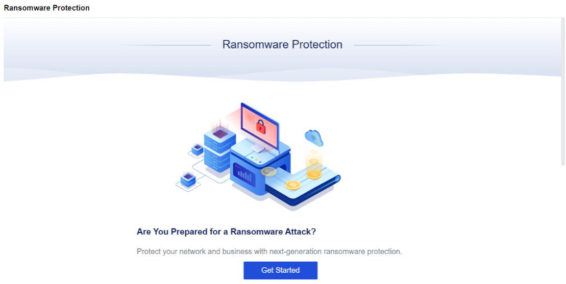
Click Get Started. The Settings page of ransomware protection appears, as shown below.
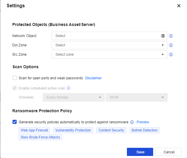
Network Object: Select the IP address group of the business asset that needs ransomware protection on the LAN.
Dst Zone: Select the zone where the business asset needs ransomware protection.
Src Zone: Refers to the attack source of a ransomware attack.
Scan for open ports and weak passwords: Authorize the Network Secure device to actively scan open ports, system, and weak passwords. This option is disabled by default.
Enable scheduled active scan: Set the time for the Network Secure device to actively scan open ports and weak passwords. This option will be gray and not selectable until you enable Scan for open ports and weak passwords.
Generate security policies automatically to protect against ransomware: Generate security policies. Once the setting is saved, policies will be generated on the Network Security Policy page. This option is enabled by default. It will also be automatically added to the top of the security policy list.
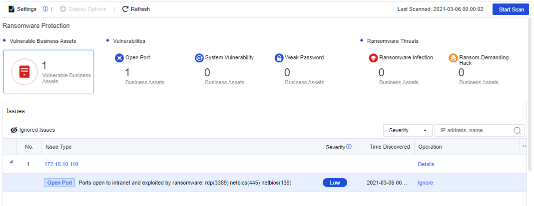
Click Save. The system will perform an assessment automatically and display the ransomware protection data, as shown below.
Click Module Display Settings, and you can add the ransomware protection module to the Home.
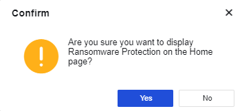
Click Yes. Then, you can see the Ransomware Protection data displayed on the Home.
IP Reputation
The Network Secure device is connected to the cloud, actively downloads the hacker IP address from the cloud, and synchronizes it to the local host to protect the business assets against intrusion from the hacker IP addresses added to the protection list. When the traffic from the hacker IP addresses passes Network Secure, the source IP address that matches successfully will be automatically blocked. In case of false positives, you can unblock the IP address. Once unblocked, the cloud hacker IP database will no longer block this IP address. The cloud hacker IP database is automatically updated every 2 hours to obtain the latest intelligence.
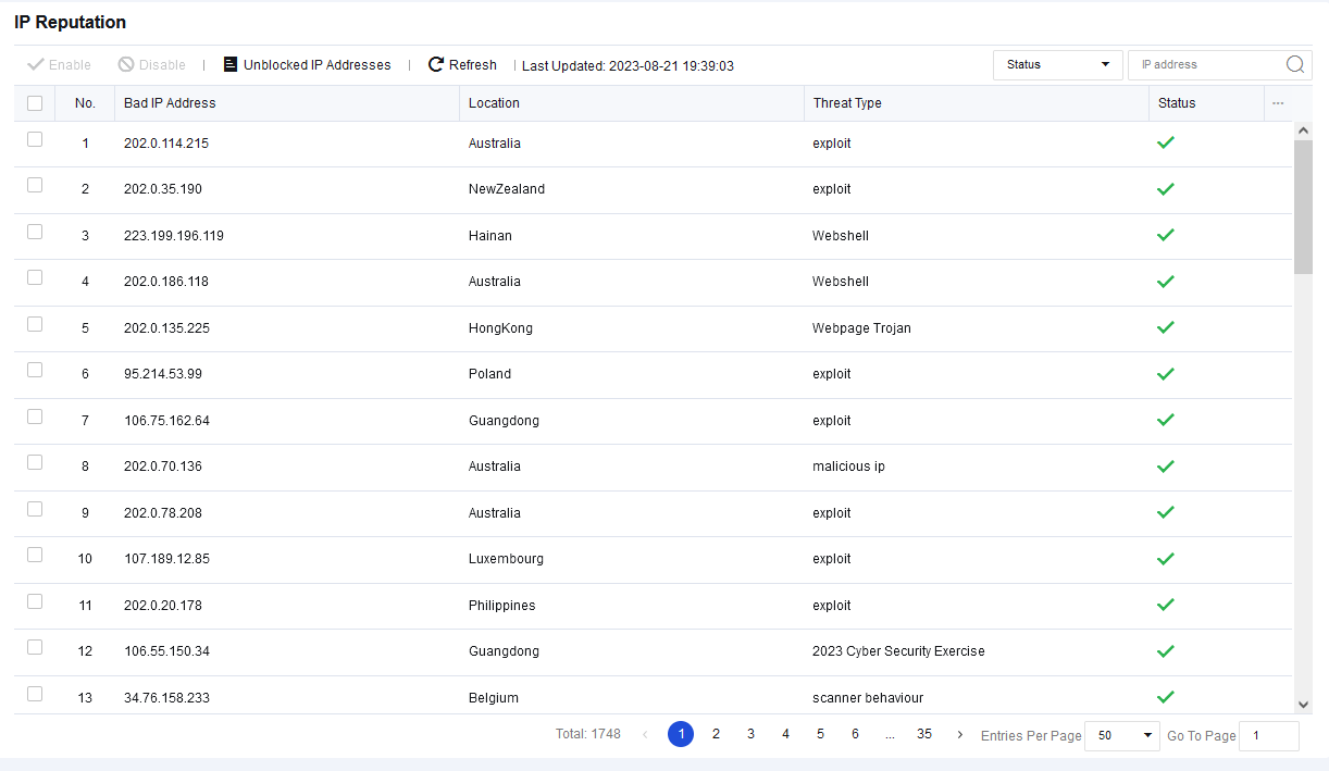
In case of false positives, you can check the corresponding IP address and click Disable. Then, in the Confirm window, click Yes to unblock this IP address as shown below:
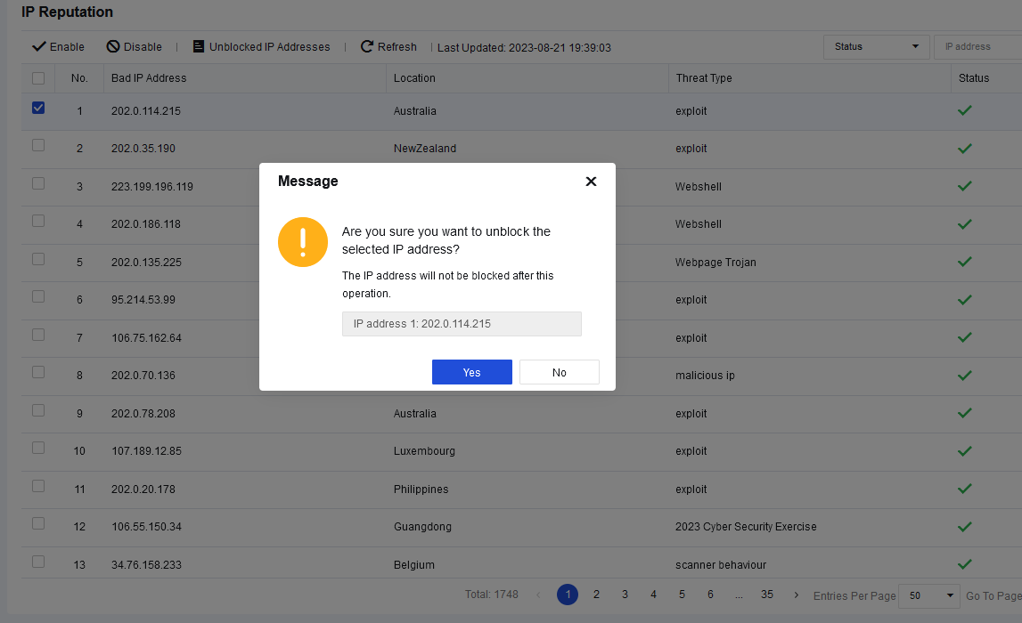
Note:
Before enabling the IP Reputation function, you must connect the Network Secure device to the Internet.
Account Protection
Account protection analyzes the business system account to see whether it has account security risks, such as weak passwords, brute-force attacks, and suspicious login. It helps the client visually analyze the security risks of the account and provides corresponding fixing and protection advice, reducing the security risks of the client’s business assets by blocking attacks from the source of attacks.
It can also help customers sort out the login URL/ports of all business assets, visually analyze whether any unnecessary login URL/ports have been developed for the business assets on the LAN, and give management suggestions accordingly to assist customers in reducing asset exposure effectively.
Prerequisites of this feature:
-
Go to Objects > Security Policy Template > Intrusion Prevention to enable Brute-force attack protection.
-
Go to Objects > Security Policy Template > Web App Firewall to enable Password Protection. Ensure that all features for weak password detection are enabled.
-
Go to Policies > Network Security > Policies to correlate more than two templates. You can see the effect only after the corresponding data is detected. For the first use, the following page is displayed.
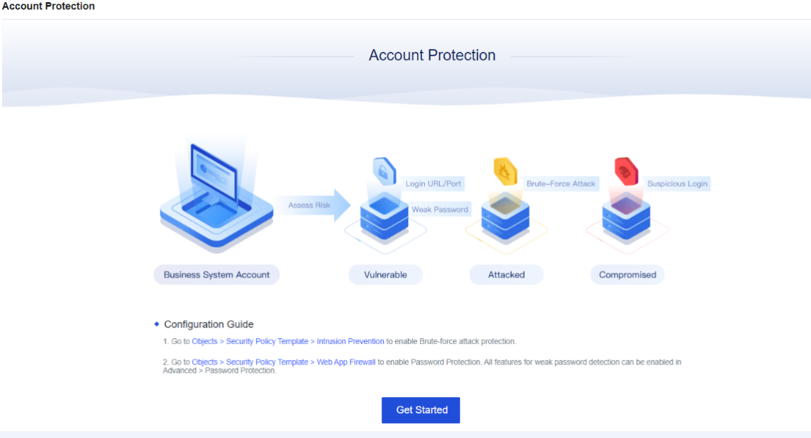
Click Get Started, and the page will change, as shown below.
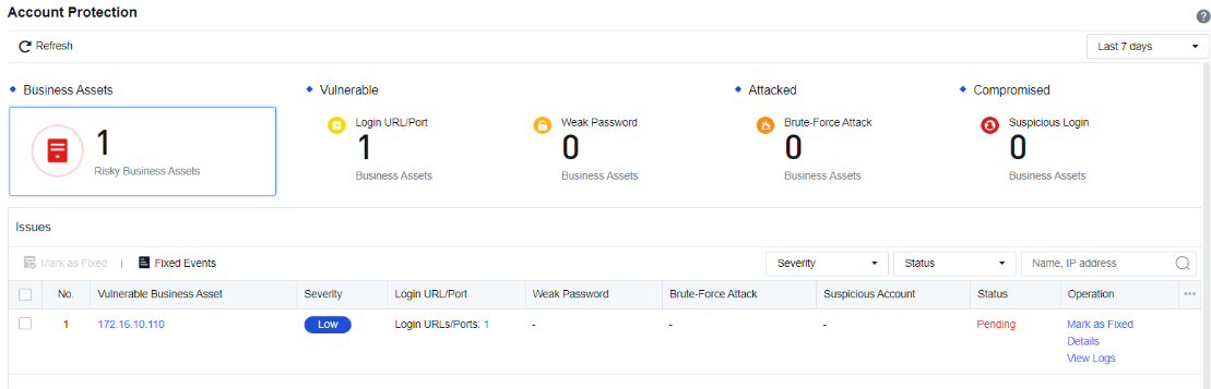
Login URL/Port: Any login operation, whether successful or not, will be detected as Login URL/Port by the Network Secure. The Network Secure will record the specific login address of an account, helping customers sort out the Login URL/Port. The interface mainly displays the protocol and address of the login.
Weak Password: It mainly helps customers sort out the business assets involving weak passwords and assists administrators in identifying which account has a weak password. The interface displays the account type, account name, and login URL/port and supports the export and fuzzy search of weak passwords.
Brute-Force Attack: If the login account has abnormalities like multiple login attempts and login failure, Network Secure will detect it as a brute-force attack. The Network Secure will record the source of the attack and block the IP addresses permanently to stop the source of the brute-force attack in time.
Suspicious Login: The successful login through multiple brute-force attacks will be detected as Suspicious Login. The Network Secure displays the suspicious login, attack source, brute-force time, etc.
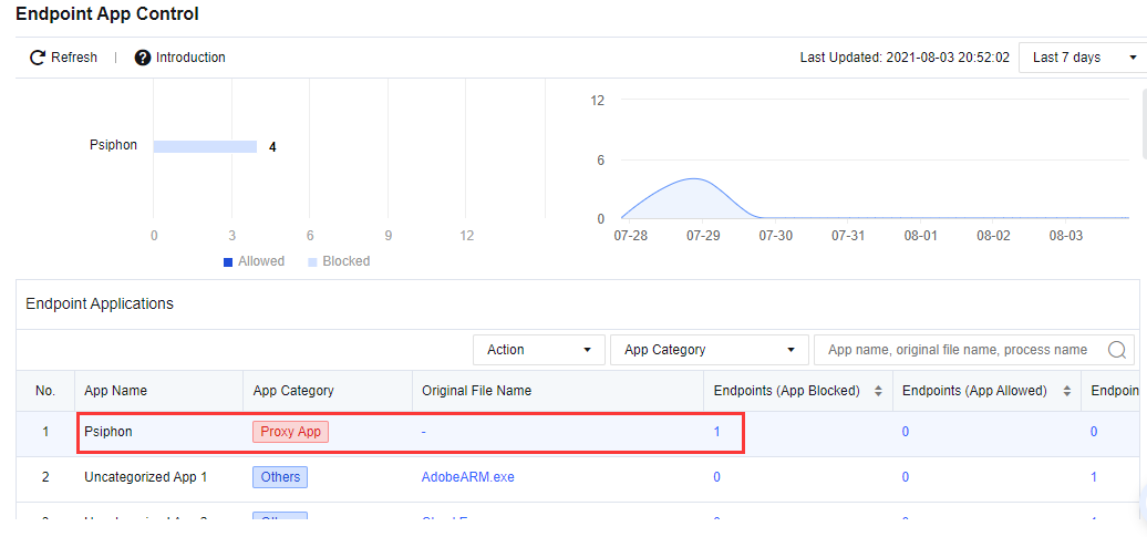
Endpoint App Control
Endpoint App control is a function used to track and control applications from the endpoint application list to prevent employees from using those apps during office hours, improving productivity and reducing network security risks.
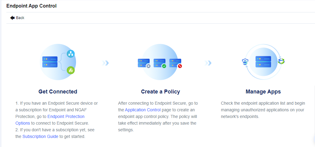
Configuration Steps to Block Proxy Tool
- Make sure that your Network Secure device is connected to Endpoint Secure Manager. To connect Network Secure to Endpoint Secure Manager, go to SOC > Next-Gen Security > Endpoint Protection > Endpoint Protection Options.
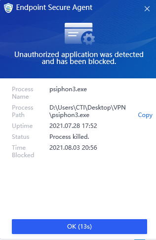
- After Endpoint Secure is connected, configure an Endpoint App Control policy. Go to Policies > Access Control > Application Control to configure the policy. For example, we want to block psisphon.
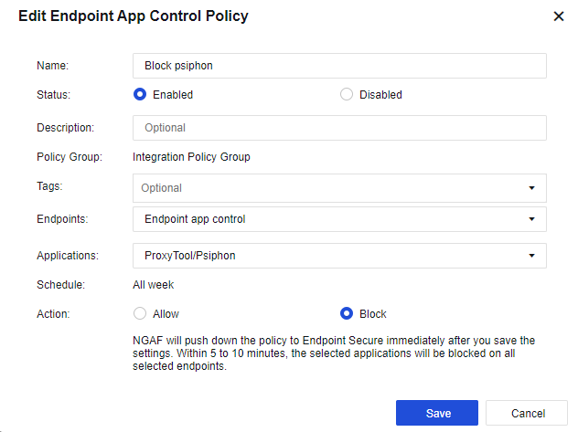
Name: Set the name of the endpoint app control policy.
Status: Set the policy as Enabled or Disabled.
Description: Set the description of the endpoint app control policy.
Policy Group: By default, all endpoint app control policies will belong to the Integration Policy Group.
Tags: Select the policy tag. This parameter is optional and can be set for displaying a specified zone or filtering.
Endpoints: Select the endpoint’s IP to be controlled.
Applications: Select the applications that are needed to control.
Schedule: By default, the policy will run all week.
Action: Set the policy to Allow or Block.
- After 5 to 10 minutes, view the endpoint app control status for the endpoint on Endpoint App Control.
Result Demonstration
Run the Psiphon application in the endpoint. ES agent will block the Psiphon application from running and prompt the alert.
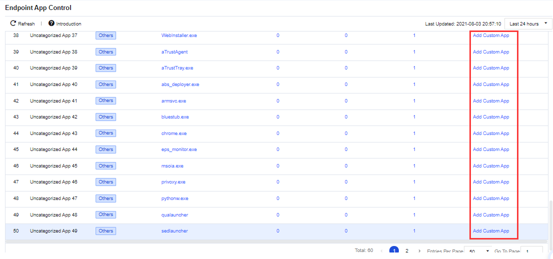
Configuration Steps to Custom Application Reported from Endpoint
- Make sure that your Network Secure device is connected to Endpoint Secure Manager. To connect Network Secure to Endpoint Secure Manager, go to SOC > Next-Gen Security > Endpoint Protection > Endpoint Protection Options.

- Go to SOC > Specialized Protection > Endpoint App Control. Create the custom endpoint application according to the list. For example, select chrome.exe as a custom application.
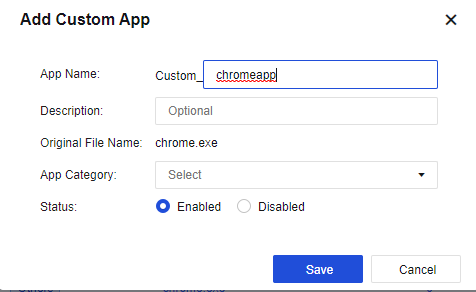
App Name: Set the application name.
Description: Set the description of the custom application.
Original File Name: The file name collected by the ES agent.
App Category: Set the application category.
Status: Set whether to Enabled or Disabled the custom endpoint application.
- After Endpoint Secure is connected, configure an endpoint app control policy. Go to Policies > Access Control > Application Control to configure the policy. Select the custom app that was created earlier.

Name: Set the name of the endpoint app control policy.
Status: Set the policy as Enabled or Disabled.
Description: Set the description of the endpoint app control policy.
Policy Group: By default, all endpoint app control policies will belong to the Integration Policy Group.
Tags: Select the policy tag. This parameter is optional and can be set for displaying a specified zone or filtering.
Endpoints: Select the endpoint’s IP to be controlled.
Applications: Select the applications that are needed to control.
Schedule: By default, the policy will run all week.
Action: Set the policy to Allow or Block.
- After 5 to 10 minutes, view the endpoint app control status for the endpoint on Endpoint App Control.
Result Demonstration
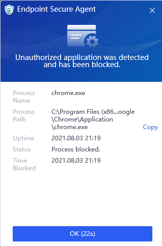
In the endpoint, run the Chrome application. ES agent will block the Chrome application from running and prompt the alert.
Blacklist and Whitelist
To set the trusted whitelist and the untrusted blacklist. The global blocking is realized via the blacklist, and global unblocking is realized via the whitelist. There are whitelist and blacklist functional modules.
Blacklist
You can add the list of addresses to be blocked by the device to the blacklist, divided into the permanent blacklist and the temporary blacklist.
Global Blacklist
To block some LAN addresses that need to be banned from accessing the WAN or block some public addresses that access attacked servers. Administrators can perform the following operations on the permanent blacklist.
| Operation | Note |
|---|---|
| Edit | Select the permanent blacklist that needs to be edited to modify the address and description. Then click Save. |
| Delete | Select the permanent blacklist that needs to be deleted. Then click Delete. |
| Clear All | All addresses on the permanent blacklist will be cleared. |
| Import/Export | Import and export the permanent blacklist. |
| Refresh | Refresh the data of the current list. |
| Search | You can search for a specific address. |
Table 7: Permanent Blacklist Operation Options
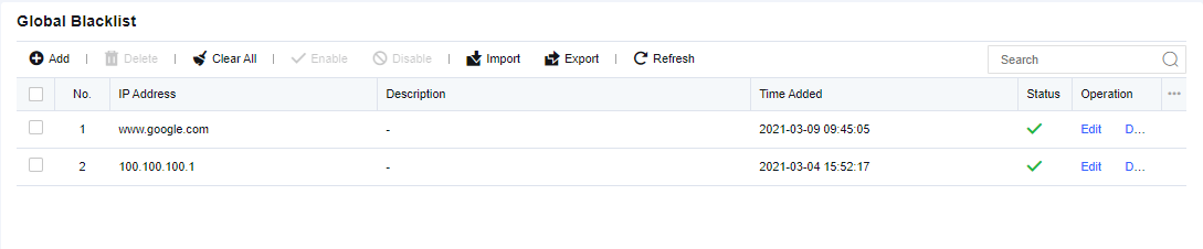
Click Add. Enter the IP addresses to be blocked and the description. Then, click Save to submit it.
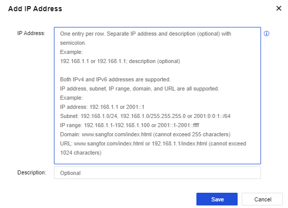
IP address: Supports IPv4, IPv6, domain name, and URL, including single address, IP network segment, and IP range.
Temporary Blacklist
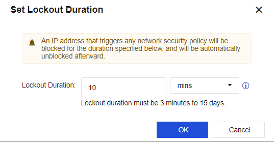
When IP blocking is enabled, check which source IP addresses have been blocked in policies related to intrusion prevention, web app protection, data leak protection, and botnet detection. It also can check which policies triggered the IP blocking and IP addresses manually added to the temporary blacklist. You can also set the lockout period. An IP address will be automatically unblocked after the lockout period expires. Administrators can perform the following operations on the temporary blacklist.
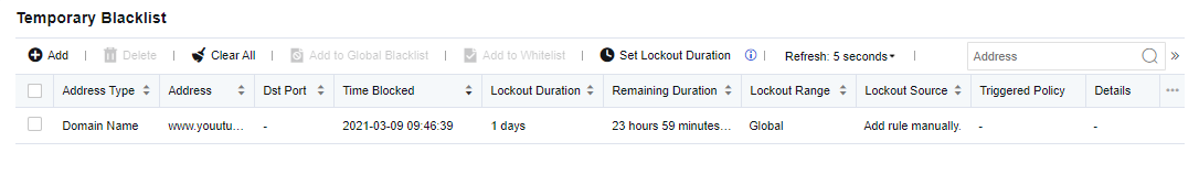
| Operation | Note |
|---|---|
| Delete | Select the permanent blacklist that needs to be deleted. Then click Delete. |
| Clear All | All addresses on the permanent blacklist will be cleared. |
| Add to Global Blacklist | Add an address to the permanent blacklist. The communication to and from the said address will be permanently rejected. |
| Add to Whitelist | Add an address to the whitelist. Addresses that have been moved into the whitelist will not be blocked by Network Secure. |
| Refresh interval | Set the refresh interval of the temporary blacklist, including four options, never, 5 seconds, 10 seconds, 20 seconds, and 30 seconds. Or, define the interval per your needs. |
| Search | You can search for a specific address. |
Table 8: Temporary Blacklist Operation Options
Click Add. Select the Lockout Range, Address Type, Type, IP address, and Lockout Duration. Then, click Save.
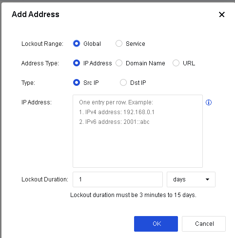
Address Type: Select the address type to be blocked, including IP address, domain name, and URL.
-
IP Address: Enter the source IP or destination IP.
-
Domain Name: Enter the domain name to be blocked.
-
URL: Enter the URL to be blocked.
Lockout Duration: Set the lockout duration, which must be 3 minutes to 15 days, so that the blocked list will be unblocked once the duration expires.
Click Set Lockout Duration. On the displayed Set Lockout Duration page, set the lockout duration for IP blocking.
Whitelist
To unblock the specified addresses. LAN users can access the Internet or the target server without being subject to any monitoring and control. Moreover, the IP address, domain name, or URL can also be excluded. Administrators can perform the following operations on the whitelist.
| Operation | Note |
|---|---|
| Edit | Select the whitelist that needs to be edited to modify the description. Then click Save. |
| Delete | Only the custom whitelist can be deleted, not the built-in whitelist. |
| Enable/Disable | Perform related operations on whitelists that need to be enabled and disabled. |
| Import/Export | Import and export the permanent blacklist. |
| Refresh | Refresh the data of the current list. |
| Search | You can search for a specific whitelist. |
Table 9: Whitelist Operation Options

Click Add. Enter the custom whitelist and description, then click Save to submit it.

Custom whitelist: Supports IPv4, IPv6, domain name, and URL, including a single address, IP network segment, and IP range.
Next-Gen Security
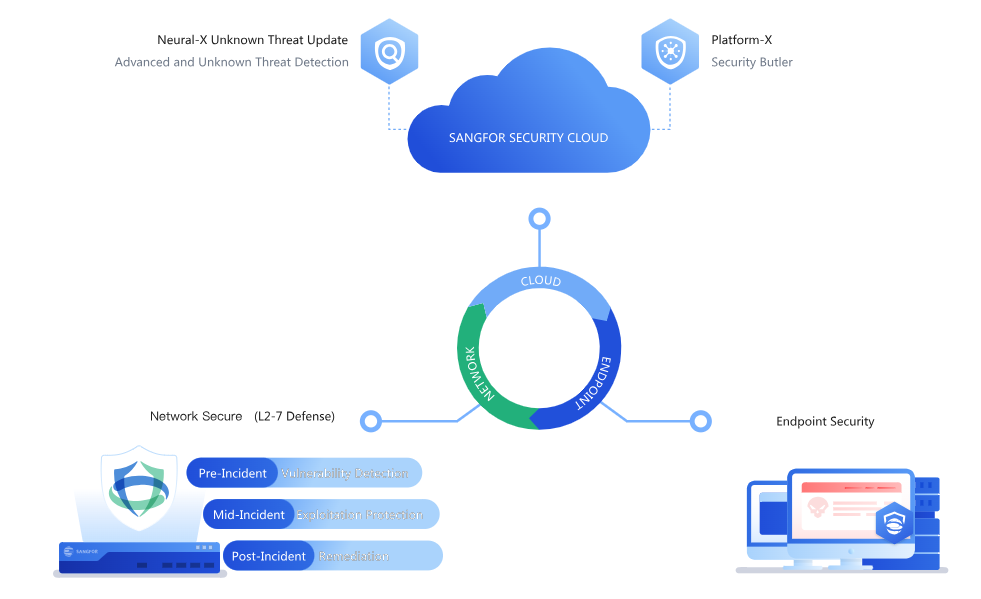
By integrating endpoint, perimeter, and cloud security devices for a coordinated response, Sangfor Next-Gen Security builds a comprehensive security defense system that provides pre-event risk warning, while-event defense, and post-event detection and response, including network-cloud correlation, network-endpoint correlation, honeypot correlation protection, and security protection functional modules.
Security Integration
It shows the corresponding products that Network Secure can correlate with, including Neural-X Unknown Threat Update, Platform-X, and Endpoint Security.
Cloud-Based Protection
To set the integration between the device and the cloud, including two functional modules: Neural-X Unknown Threat Update and Platform-X.
Cloud-Based Protection Options
Cloud-Based Protection Options allows Network Secure to integrate with cloud-based products such as Neural-X Unknown Threat Update and Platform-X, as shown in the following figure.
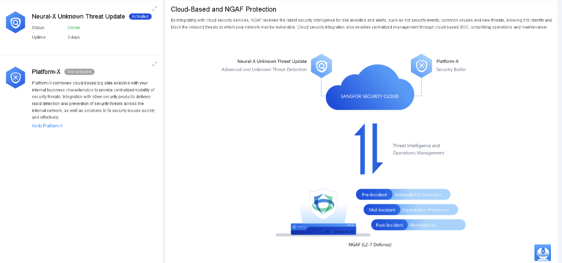
Neural-X Unknown Threat Update
Sangfor Neural-X Unknown Threat Update is a comprehensive detection and protection service based on multiple engines, including cloud-based sandbox, behavior analytics, and threat intelligence. It provides great cloud security capabilities to detect and protect against unknown threats, including advanced variants and emerging threats that traditional rule-based signatures cannot defend against.
To integrate Network Secure with Neural-X Unknown Threat Update, ensure your device has Internet access and activate the Neural-X Unknown Threat Update license.

Platform-X
Sangfor Platform-X provides a unified display of security risks based on its cloud-based big data analysis capabilities and your internal network’s characteristics. It implements rapid response through integration with cloud and network security products, helping you defend against potential threats and detect security issues within the internal network.
To integrate Network Secure with Platform-X, register your corporation on Platform-X and specify the corporation ID, device name, and access token on the Integration Settings page, as shown in the following figure.
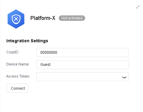
Click Connect to complete the integration, as shown in the following figure.

Neural-X Subscription
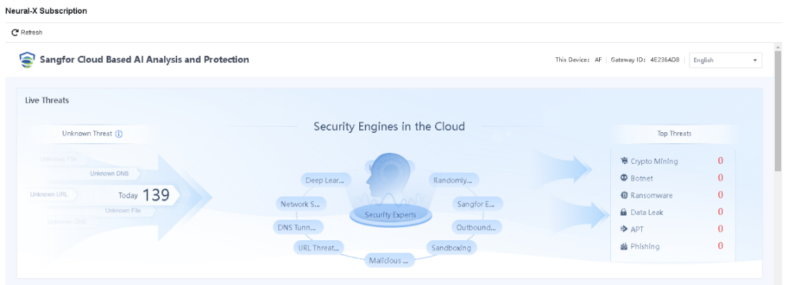
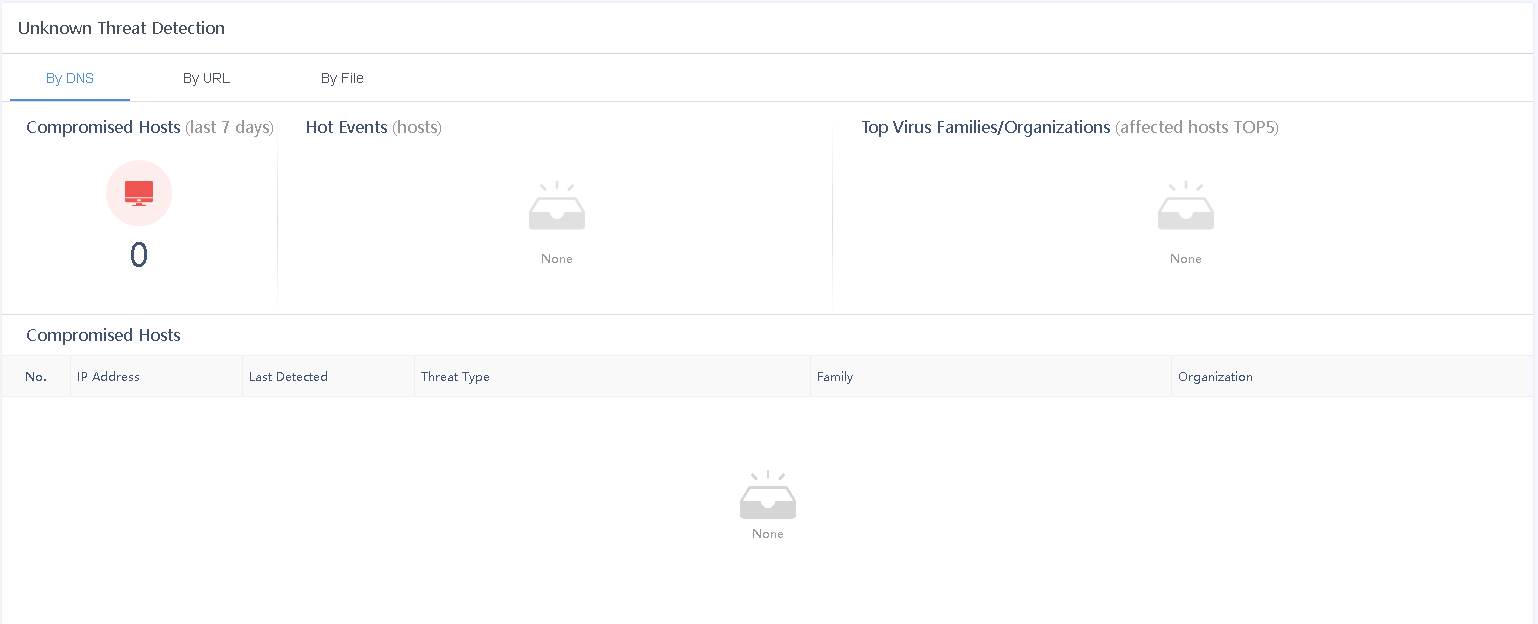
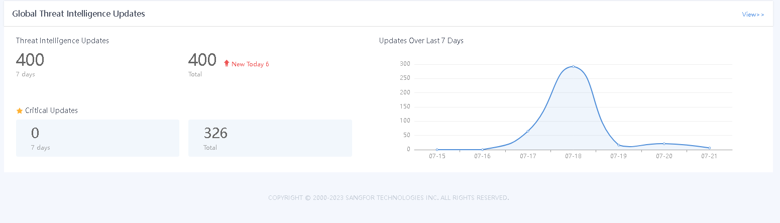
Sangfor Neural-X Subscription offers enhanced capabilities to detect emerging, unknown, and advanced threats through continuous autonomous learning. It maintains deep integration with Network Secure to improve device security capabilities and ensure user network security.
Devices are automatically integrated with Neural-X Subscription once they have access to the Internet, and you obtain the license for Neural-X Subscription. After the integration, you can view information related to threat intelligence on the Neural-X Subscription page, as shown in the following figure.
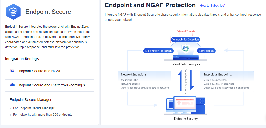
Endpoint Protection
Endpoint and Network Secure Protection enable the ES to share security information with the Network Secure, thus implementing the association of network and endpoint security information, making threats more detectable and easier to handle.
Endpoint Protection Options
Endpoint Protection Options allow you to integrate Endpoint Secure with Network Secure. Sangfor Endpoint Secure is a comprehensive and effective platform that provides continuous detection and rapid response to endpoint threats based on the AI-powered SAVE engine, behavioral engine, cloud engine, and reputation database. When integrated with Network Secure, Endpoint Secure delivers a highly coordinated and automated defense platform for multi-layered protection.
Two integration methods are available for Endpoint Secure: Endpoint Secure on Platform-X and On-Premises Endpoint Secure Manager.
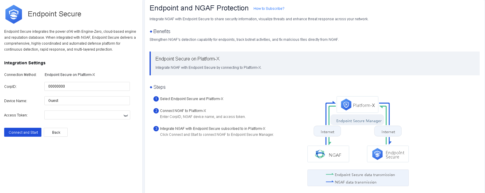
Endpoint Secure on Platform-X
For Endpoint Secure on Platform-X, Endpoint Secure Manager is deployed on Platform-X. Before integrating Network Secure with Endpoint Secure, you must connect them to Platform-X, as shown in the following figure.
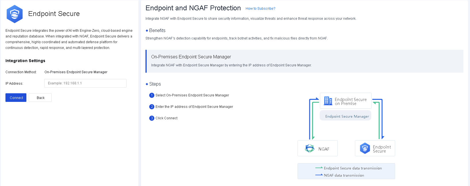
On-Premises Endpoint Secure Manager
For On-Premises Endpoint Secure Manager, Endpoint Secure Manager is deployed locally. You can integrate Network Secure with Endpoint Secure by entering the IP address of Endpoint Secure Manager, as shown in the following figure.
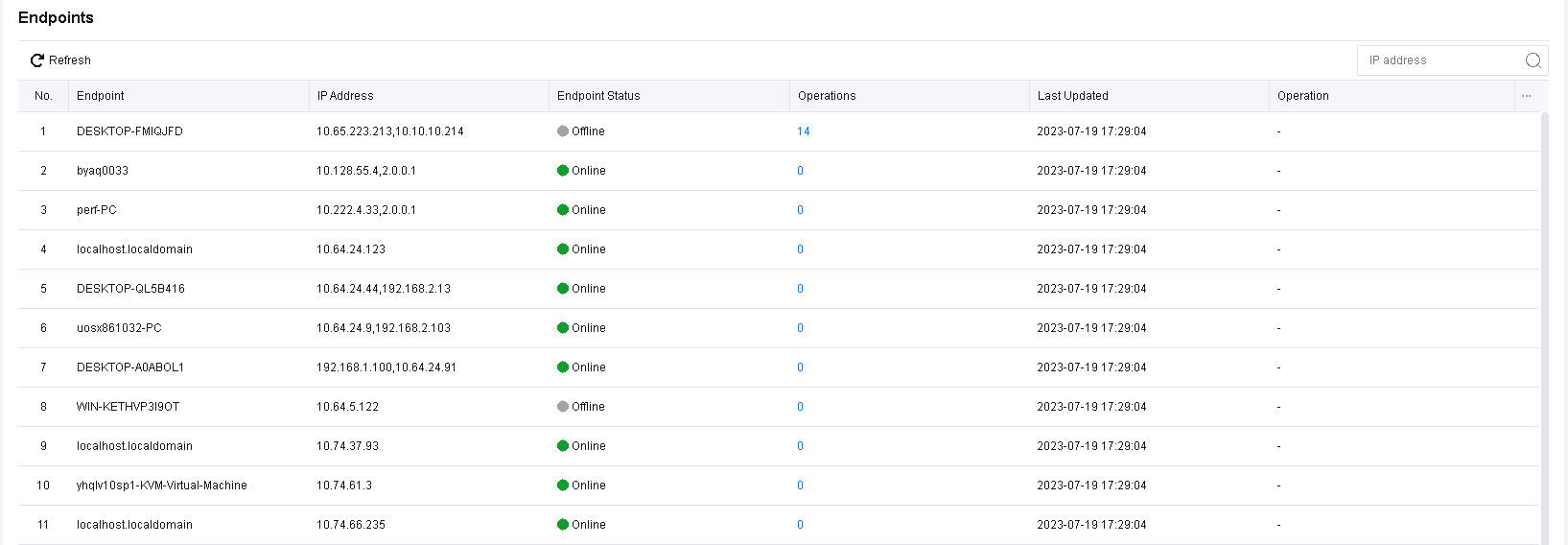
Endpoints
Endpoints display Endpoint Secure endpoint information, including the Endpoint, IP Address, Endpoint Status, Operations, Last Updated, and Operation columns. The Endpoints page is refreshed once an hour, and you can filter endpoints by IP address.
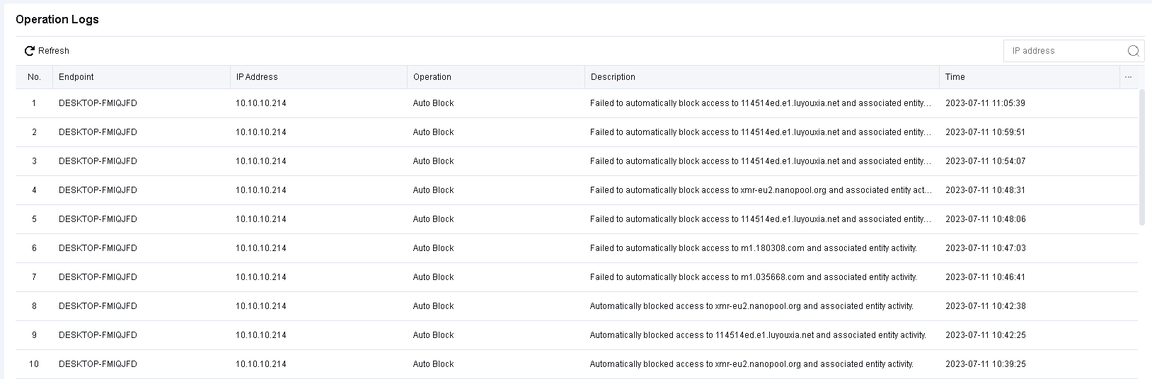
Operation Logs
Operation Logs displays the operations logs on endpoint files by integrating Network Secure with Endpoint Secure, as shown in the following figure.
Security Capabilities
Security Capabilities displays the update capabilities of devices. It consists of five parts: the security capability map, Update Overview, Updates, Top 10 Hot Events, and Update Calendar.
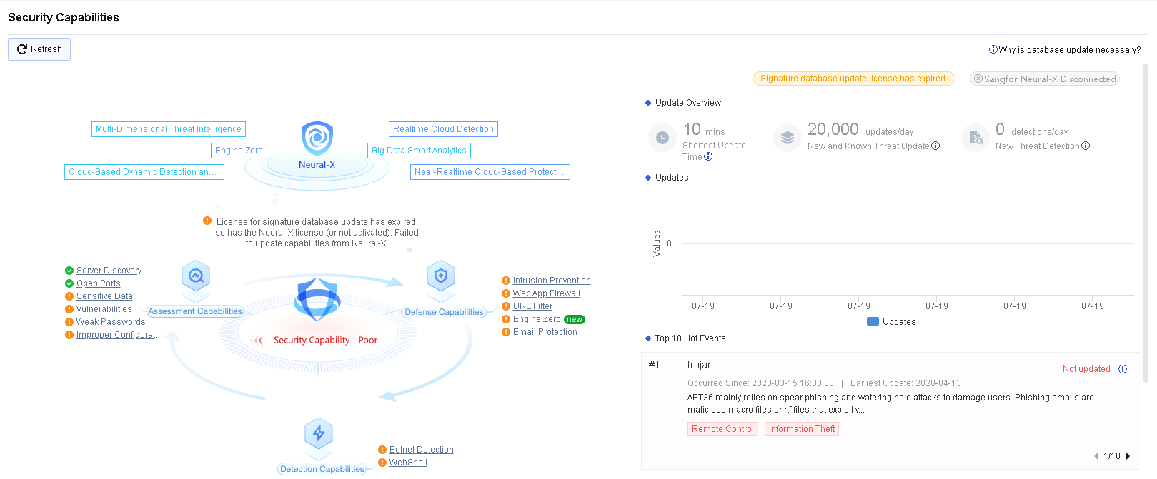
Security capability map: Presents the integration updates between Network Secure and other Sangfor products and displays real-time updates of pre-event risk discovery capabilities, during-event risk defense capabilities, and post-event risk detection capabilities.
Updates: Displays ongoing updates and the real-time data of related hot events in a trend graph.
Top 10 Hot Events: Displays the top 10 hot events in real time.
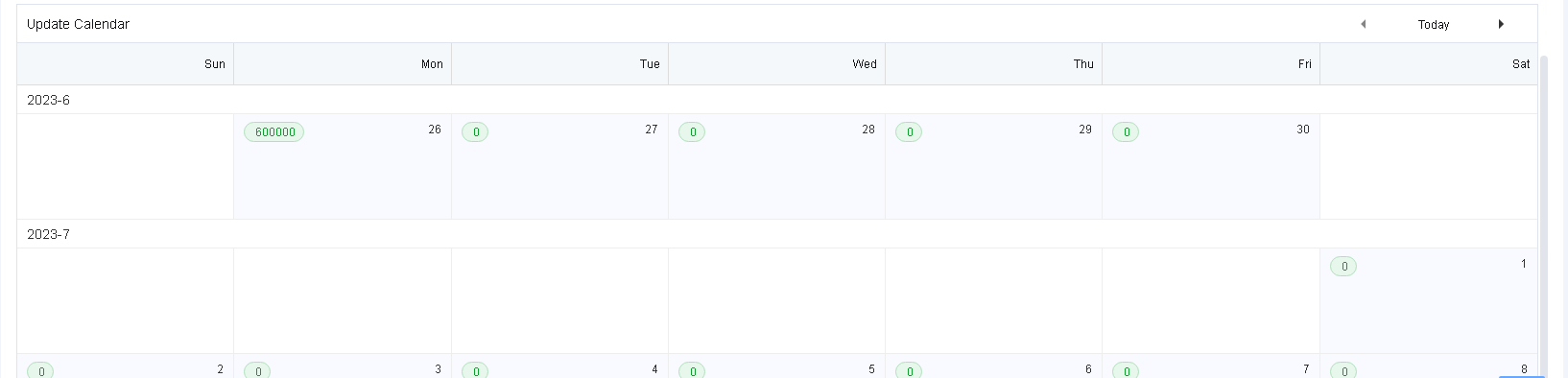
Update Calendar: Displays the types and the number of database updates of each date in a calendar.
Monitor
To view all logs generated by the Network Secure device. It is the log center of the Network Secure device. Meanwhile, reports can be generated corresponding to the generated logs, thus improving the efficiency of manual analysis. Monitoring functions include TOP N, security logs, access logs, system logs, sessions, statistics, report, settings, and other modules.
Logs
During the operation of the security device, a large number of systems, security, and running logs will be generated. The log functions are to record the security, access, and system logs generated by the device for convenient viewing and analysis.
There are three ways to store log files: firewall (local), Cyber Command (CCOM) system, and Syslog.
The firewall stores log files locally by default, which is mainly restricted by the size of the device’s disk. To meet compliance requirements, it is recommended to store log files by using firewalls combined with CCOM. This method is adopted on the one hand to meet the requirements of performing storage backup according to the rules, on the other hand, to ensure that the CCOM can store massive logs and assist in traceability analysis.
Security Logs
Security Logs mainly record security attack events generated by the device. See the figure below.

Security Logs
Security logs mainly record service attack behaviors, including Web app protection, intrusion prevention, Bonet, website access, email security, and DoS attacks. If an attacking threat triggers the security policy, it will be logged into the security log. If the attack event is determined to be a misjudgment, the attack event can be added to the exceptions for exclusion, and if it is judged to be a real attack threat, the attack event can be dealt with according to the solution guidelines provided in the log details. You can export logs to perform an analysis or enter the IP address or domain name in the search box to search for the corresponding log information. See the figure below.
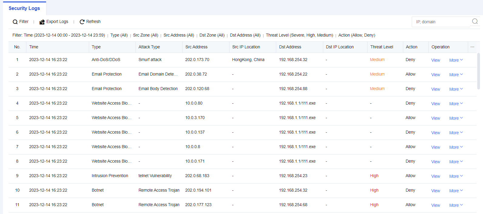
Security Log Retrieval Case
A network administrator in an enterprise discovers that a Web server is under attack. It is necessary to review the Web protection logs, determining the attacking IP address(es) and the means used in the attack, and other information.
- Click Filter and select the search criteria according to needs, as shown in the figure below.
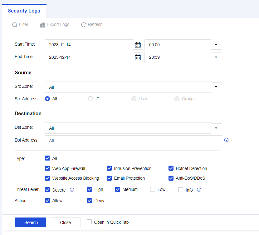
| Search Criteria | Note |
|---|---|
| Start/End Time | Select start time and end time for querying. |
| Src Zone | Source zones of logs. |
| Src Address | Source IP addresses of attackers. |
| Dst Zone | Zones where destination IP addresses of attacks reside in. |
| Dst Address | IP addresses attacked by attackers. |
| Type | Perform filtering according to different log types. |
| Threat Level | Filtering according to different security levels. |
| Action | Filtering according to log actions. |
Table 10: Description of Log Search Criteria
- Select Start Time and End Time as needed. Check the Web App Firewall to view Web App Firewall logs, as shown in the following figure.
- View Web App Firewall logs, as shown in the following figure.

Note:
Logs reveal that the source of the attack, 192.200.19.4, attacked the target server, 192.168.254.61.
- Click View to check whether the attack behavior is a false positive, as shown in the following figure.
Basics: Describe the attack behavior, such as matching Rule ID and request method.
Data Packet: Record the complete request information of the data packet, and the part highlighted in red indicates the feature of the attack.
You can determine whether it is a false positive by viewing the log details. If it is, add the attack event to the exceptions. Click More under Operation on the right side of the Security Logs page, and then select Exclude. A dialog box will appear, as shown in the following figure.
URL: The URL to be matched.
Exclusion Options:
Exclude: Add the matched Src and Dst IPs, Dst Port, and Rule ID as exceptions.
Only exclude requests for the URLs whose parameters match any of the following: These parameters will be excluded when performing website attack detection of Web App Firewall. For normal business scenarios where certain request parameters are detected as attacks because of the specific signature strings they contain, you can select this option to exclude such parameters exclusively.
Note:
- Starting from the 8.0.47 version, exporting multiple security types at the same time is supported.
- The maximum number of logs that can be exported at the same time is 100000 entries.
Access Logs
Access Logs mainly record the processing results of the user/IP traffic after it is being received by the Network Secure device, and session logs record the ACL information that can be matched. Access Logs include Session logs, User Login/Logout Logs, and SSL VPN Logs.
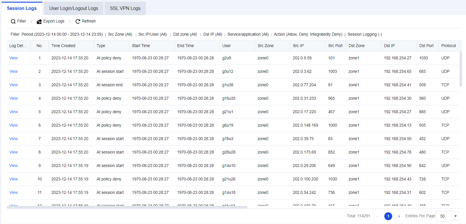
Session Logs
Session logs are used to check which application control policy the traffic matches to facilitate troubleshooting. See the figure below.

Session Logs Retrieval Case
In an enterprise’s network, it is required to specify a policy, with certain access ports determined. Therefore, after enabling Log events in the firewall Application Control Policy, search logs in the Session Logs.
- Click Filter to perform Src/Dst IP filtering according to needs, as shown in the figure below.
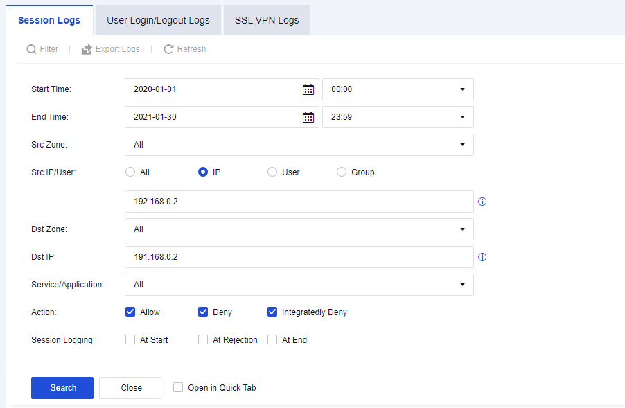
- According to the results, determine whether the port and service are normal, as shown in the figure below.
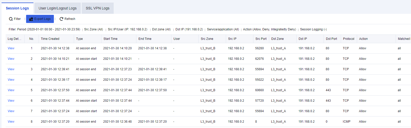
Note:
How to enable Application Control Policy:
- Navigate to Monitor > Settings > Logging Options > Logging and Archiving, Enable the Application Control Logs, and check Local. You can choose other storage methods if there are external devices.
- Navigate to Policies > Access Control > Application Control > Policies, select the corresponding application control policies and enable the Log events function.
User Login/Logout Logs
User Login/Logout Logs are mainly used to query the recorded details about a user’s login and logout through the Network Secure authentication module after the module is enabled. You can export logs for performing analysis, as shown in the following figure.
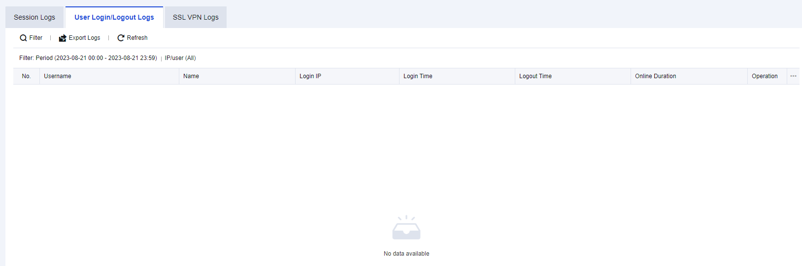
User Login/Logout Logs Retrieval Case
An enterprise authenticates the networking behavior of the PCs on its office LAN, and only the authenticated endpoints can access the Internet.
- Click Filter to perform log filtering according to needs, as shown in the figure below.
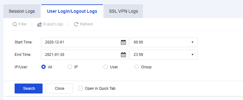
- The result records the device’s Login Time, Logout Time, and Online Duration, as shown in the figure below.
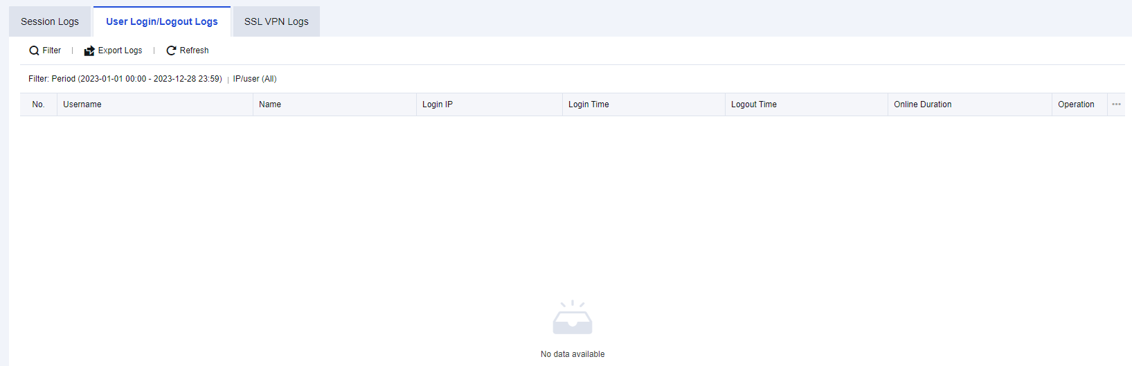
SSL VPN Logs
SSL VPN Logs record information such as login, logout, and terminal PC version of SSL users to facilitate administrators’ troubleshooting of abnormal user behavior. You can export SSL VPN logs for performing analysis, as shown in the following figure.
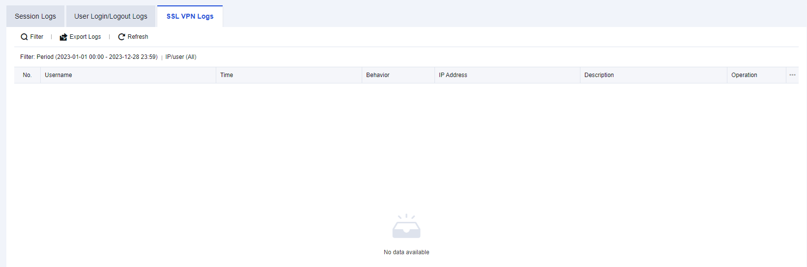
SSL VPN Logs Retrieval Case
An enterprise administrator finds a user abnormal and needs to retrieve the user’s recent logins.
- Click Filter to look up the user’s recent logins, as shown in the figure below.
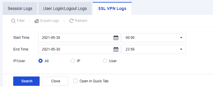
- The results display the endpoint Username, operation time, behavior, IP address, and other information, as shown in the figure below.

System Logs
System Logs mainly record the logs generated when device administrators perform operations on devices, the local security logs generated when devices are under attack, and the local access control logs. These logs can be exported and provided to relevant personnel for analysis, as shown in the following figure.

Admin Operation Logs
To query the login and logout logs of users logging in to the control panel and the logs of all operations executed. For example, you can query the operations executed by the account Admin after logging in to the console on a particular day. The Admin Operation Logs page is shown below.
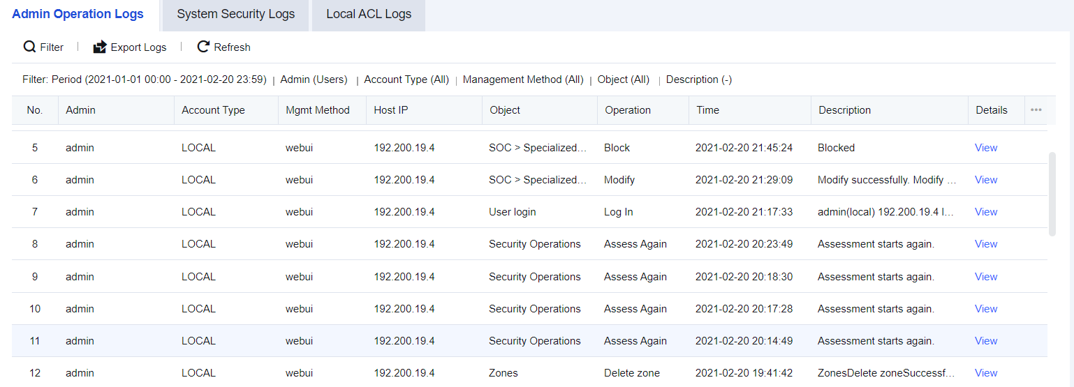
Admin Operation Logs Retrieval Case
It is necessary to retrieve which administrator accounts have been recently used to configure Zones for the network of a particular enterprise.
- Click Filter to retrieve the configuration details of Zones, as shown in the following figure.
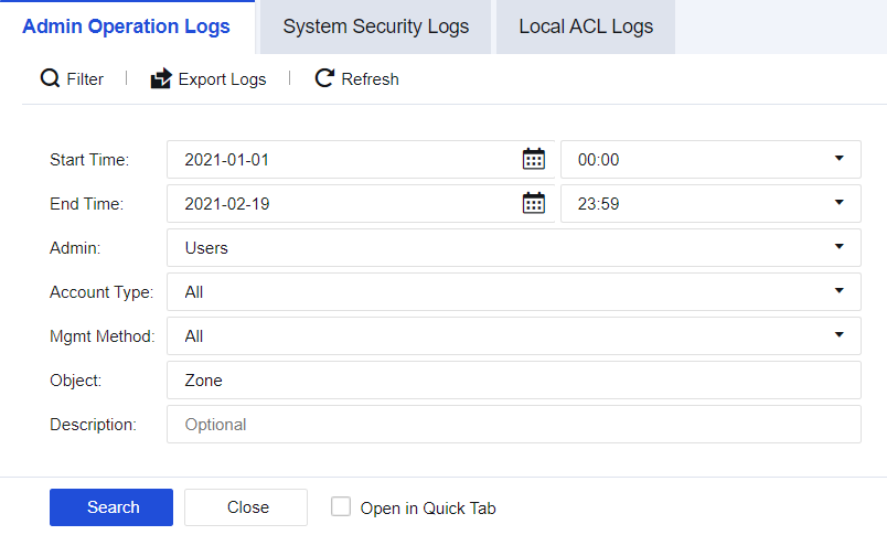
- View the results that list the Admin accounts used, operation time, hosts, and other information for Zone configuration.
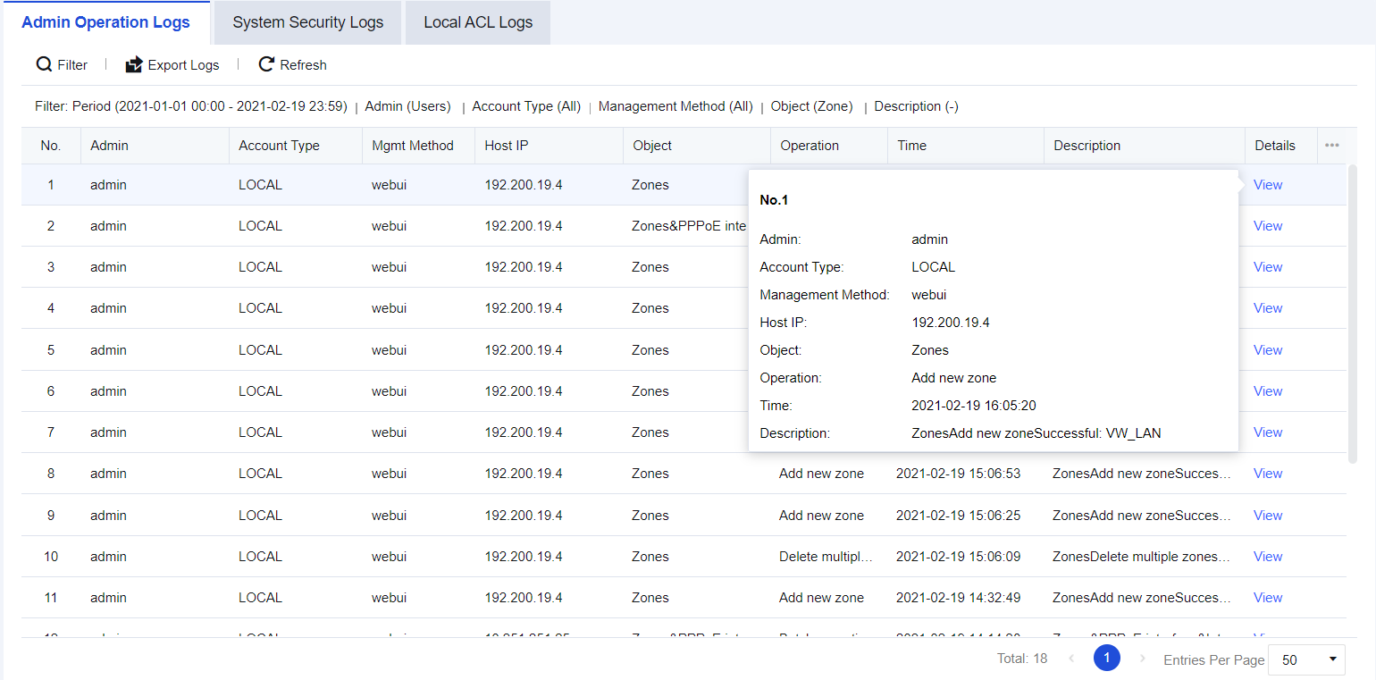
System Security Logs
Network Secure devices have the function of resisting penetration attacks. When a device suffers a malicious attack, you can view the System Security Logs and perform analysis. System security logs record detailed information about attacks suffered by Network Secure devices. The System Security Logs page is shown below.
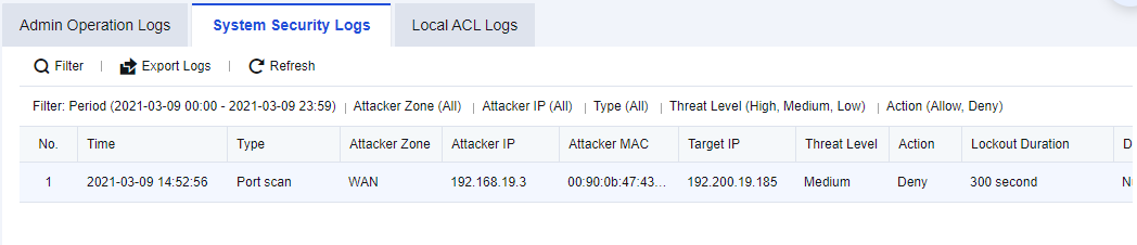
System Security Logs Retrieval Case
An enterprise needs to perform local device security protection to check whether the devices are attacked periodically. Therefore, administrators need to check all the system security logs to determine whether there are abnormalities in devices.
- Click Filter to perform log filtering according to needs, as shown in the figure below.
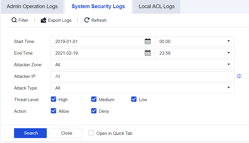
- View details of specific attacks, as shown in the figure below.
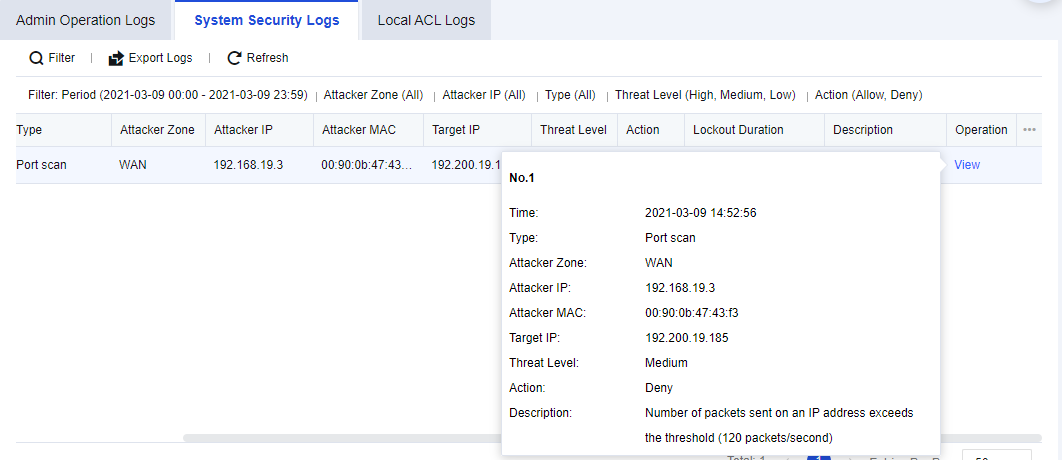
- The attack types that can be queried include port scanning, ICMP flood attack, UDP flood attack, SYN flood attack, DNS flood attack, and IP messages in the blacklist.
Note:
How to enable System Security logging:
- Navigate to Policies > Network Security > Anti-DoS/DDoS, select This Device Protection, and check Enable.
- Select the scan and attack types and check Log events and other functions.
Local ACL Logs
The Network Secure device possesses its access control policy. It is a policy designed for endpoints accessing the Network Secure. You can check which policies have been matched when endpoints access Network Secure according to the logs. The Local ACL Logs page is shown below.
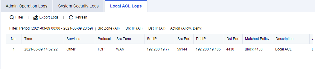
Local ACL Logs Retrieval Case
An enterprise needs to check which endpoints have accessed the Network Secure device and determine whether the access was normal.
- Click Filter to perform log filtering according to needs, as shown in the figure below.
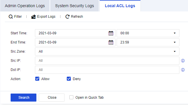
- You can check the source and destination IP addresses and other information about specific access from the results. Click View to view the details, as shown in the following figure.
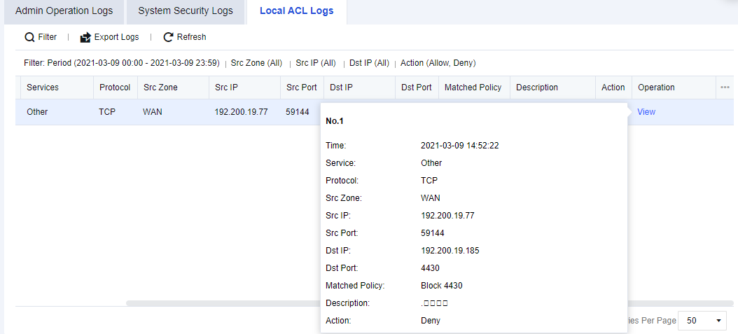
Note:
How to enable Local ACL logging:
- Navigate to Monitor > Settings > Logging Options > Logging and Archiving, Enable the Local ACL Logs and check Local. You can choose other storage methods if there are external devices.
- Navigate to Policies > Access Control > Local ACL, and enable the Log events for corresponding policies as needed.
TOP N
Top N Options allows you to monitor and rank devices, apps, source IP addresses, destination IP addresses, and interfaces based on their traffic or new sessions.
Configuration Procedures
- Enable Top N Options. Go to Monitor > Settings > Top N Options, check Enable, and click Save.
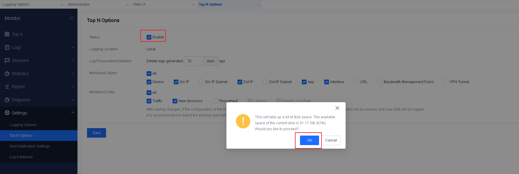
- Add a monitor component. Go to Monitor > Top N > Network Monitor and click Add Component.
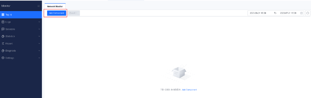
- Select an option for Monitored Object and Monitored Data. You can select Device, Src IP, Dst IP, App, or Interface for Monitored Object and Traffic or New Sessions for Monitored Data.
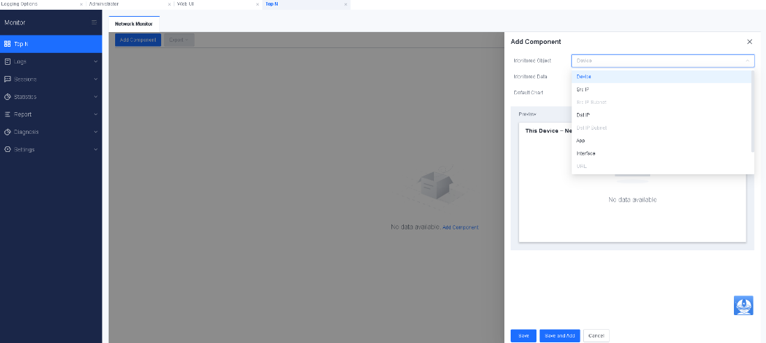
- Select a chart type. The options include Bar, Area, Line, and Pie.
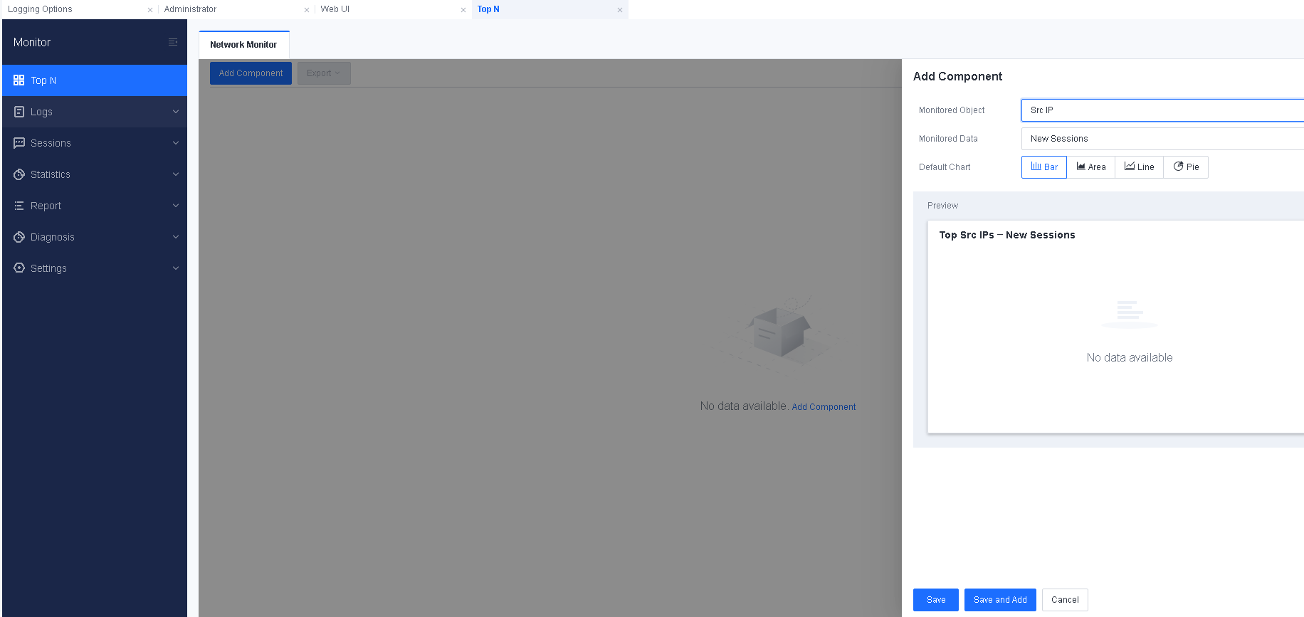
- Click Save and Add. To add more components, repeat the preceding steps.

Sessions
To record the number of sessions generated by traffic, the volume of traffic generated, and the traffic that triggers abnormalities. The number of sessions can be ranked to distinguish the number of sessions created from different IP addresses. The functions of Sessions include traffic ranking, suspicious traffic, session ranking, and traffic management status.
Session List
Session List displays sessions created through the firewall. You can query sessions in real time, filter sessions by multiple conditions, export sessions in bulk, and terminate abnormal sessions in bulk, as shown in the following figure.

To view the details of a session, click the corresponding icon in the Session Details column, as shown in the following figure.
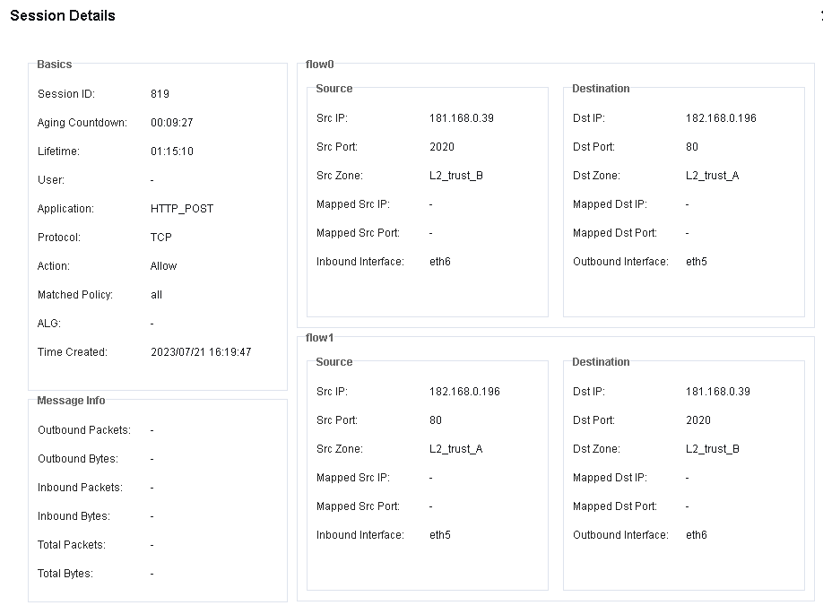
Traffic Ranking
The traffic statistics are performed mainly based on users, applications, and IP addresses for traffic rankings. Functions include Top User by Traffic, Top Applications by Traffic, Top IP Addresses by Traffic, and Traffic by IP Address.
Top Users by Traffic
Top Users by Traffic ranks the users who have got the authentication for accessing the Internet by counting their traffic, displaying the bandwidth usage of online users. The Top Users by Traffic page is as shown below.
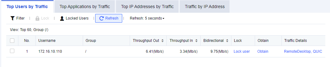
Case of Viewing Top Users by Traffic
An administrator needs to view which applications the user has accessed during office hours on an enterprise’s network.
- Click Filter. The administrator can specify the filter conditions for user traffic ranking. See the figure below.
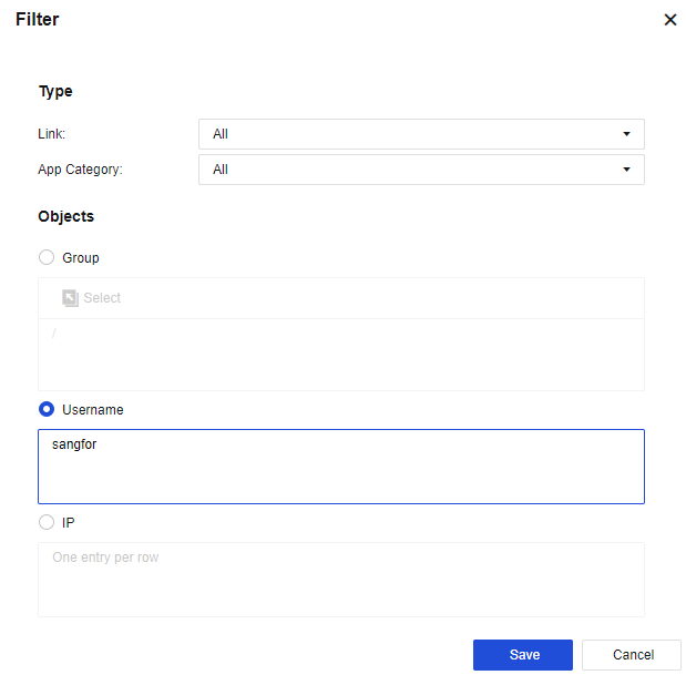
Link: Select the specific link to view.
App Category: Specify the application service to view.
Objects: Set a specific username or IP.
- Check the search results, as shown in the following figure.
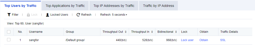
Perform ranking based on the bidirectional throughput of users and display information of the following items: Username (displayed name), Group, Throughput Out/In, Bidirectional, Lock, Obtain, and Traffic Details. Click Lock to block Internet access for a user. In the Obtain column, click Obtain to find out the computer name of the user. In the Traffic Details column, click the specific application to enter the following page, which shows the application traffic usage of the user.
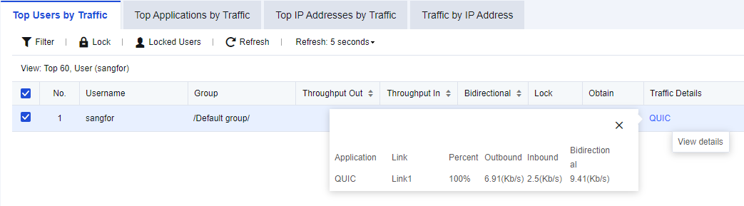
- (Optional) Enable Lockout Duration to lock a user immediately so that the user cannot access the Internet within the specified duration. Select a user listed on the Top Users by Traffic page, click Lock user in the Lock column, and set the Lockout Duration (mins), as shown in the following figure.
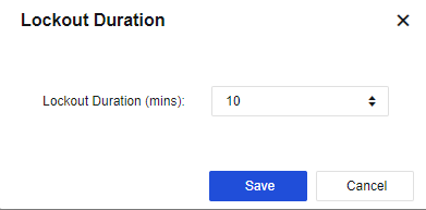
- (Optional) Unlock Internet access for users. To immediately lift the restrictions on users being locked to allow them to access the Internet, click Locked Users and go to the Authentication Status page, as shown in the following figure.
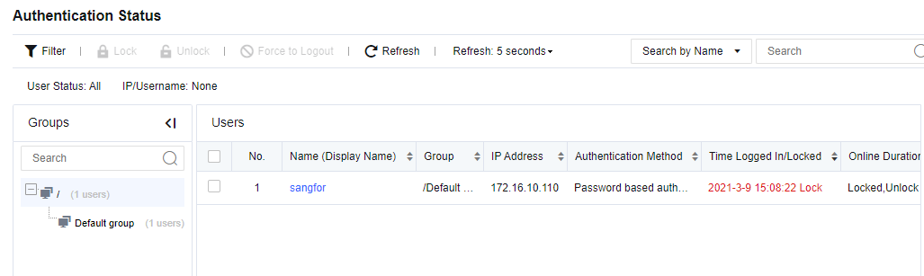
Find the locked user displayed on this page, select the user and click Unlock.
Top Applications by Traffic
Top Applications by Traffic ranks the real-time application traffic when traffic flows through the device. You can view the current traffic statistics per application, or filter data according to filter conditions. The Top Applications by Traffic page is as shown below.
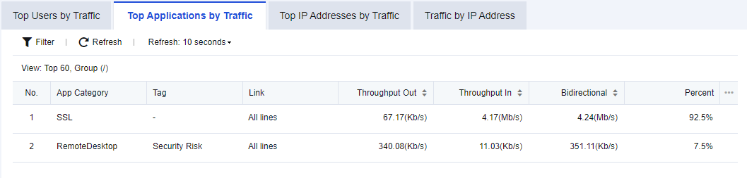
Applications are ranked based on their bandwidth. Information of the following items is displayed: App Category, Tag, Link, Throughput Out/In, and Bidirectional.
Click Refresh: 5 seconds to set the refresh interval of rankings on the page.
Click Refresh to refresh the page immediately.
Notice:
- Top Applications by Traffic supports application traffic ranking in IPv6.
- Currently, there are few tags available, including the High Bandwidth Consumption, Reduced the Efficiency of Work, Saas, Security Risk, Disclosure Risk, and more.
- To enable Top Applications by Traffic, you need to enable the log control switch under Logging Options.
Top IP Addresses by Traffic
Top IP Addresses by Traffic shows the bandwidth usage of online IP addresses, as shown in the following figure.
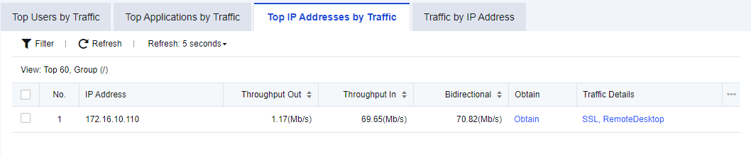
The ranking is based on the bidirectional throughput of IP addresses and the information displayed includes the following items: IP Address, Throughput Out, Throughput In, Bidirectional, Obtain, and Traffic Details. In the Obtain column, click Obtain to find out the computer name corresponding to the IP address. In the Traffic Details column, click the specific application to enter the following page, which shows the application traffic usage for the IP address.
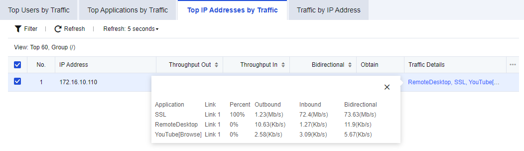
Click Refresh: 5 seconds to set the refresh interval of rankings on the page.
Click Refresh to refresh the page immediately.
Top IP Addresses by Traffic supports viewing IP address traffic ranking in IPv6.
Traffic by IP Address
The Traffic by IP Address chart shows the traffic trend of IP addresses.
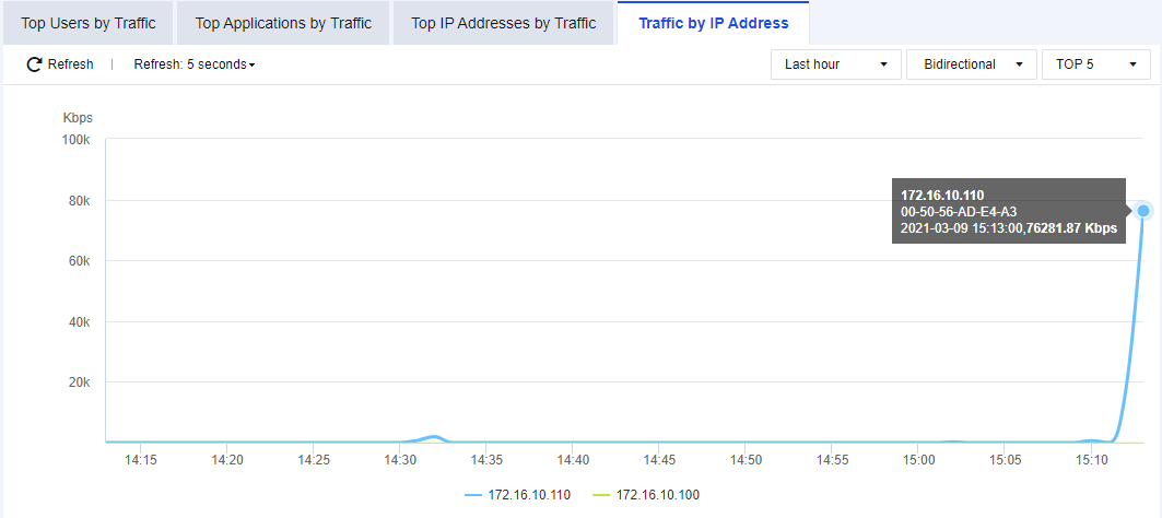
As shown in the figure, the latest TOP 5 and TOP 10 IP addresses with the highest traffic trend are displayed.
Suspicious Traffic
Suspicious Traffic shows abnormal connection data of botnet detected, provided that you have enabled the function of detecting abnormal connections in Botnet, as shown in the following figure.
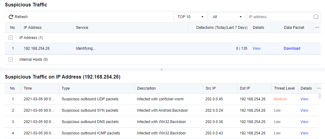
This page shows the details of abnormal connections, including Time, Type, Src IP, Dst IP, Threat Level, Description, and Details.
Session Ranking
Session Ranking shows the number of sessions created when traffic flowing through the Network Secure device. Session ranking and session querying can be performed according to IP addresses.
Session Ranking
Session Ranking ranks IP addresses by the number of sessions created when business traffic passes through the Network Secure device.
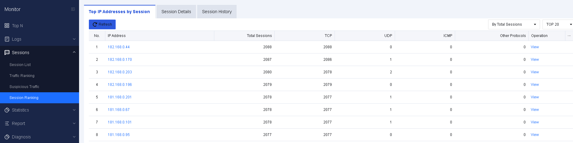
On the Session Details tab, click View in the Operation column to view the session details of an IP address, as shown in the following figure.
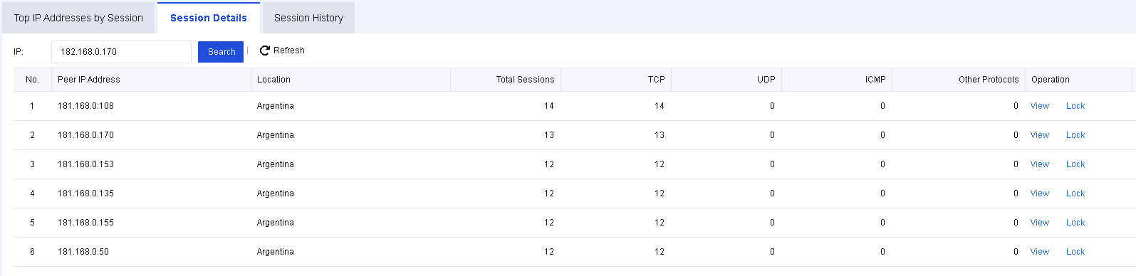
Session Details
Session Details is to query the specified LAN IP address and count the number of sessions based on the peer IP address of the session, as shown in the following figure.
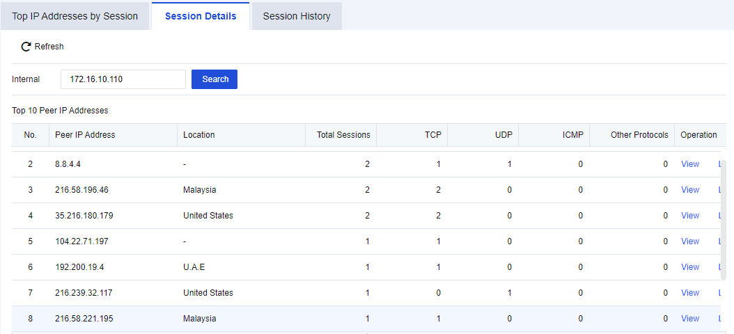
Click View to view session details, as shown in the following figure.
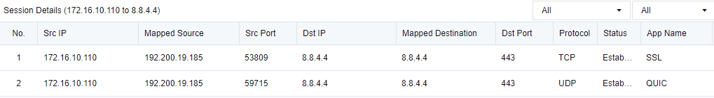
Click Lock to lock the session IP, as shown in the following figure.
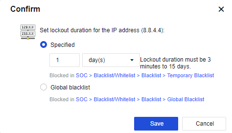
Session History
Session History presents the number of new and concurrent sessions made by an IP address. To use this function, you need to set the monitored IP group first.
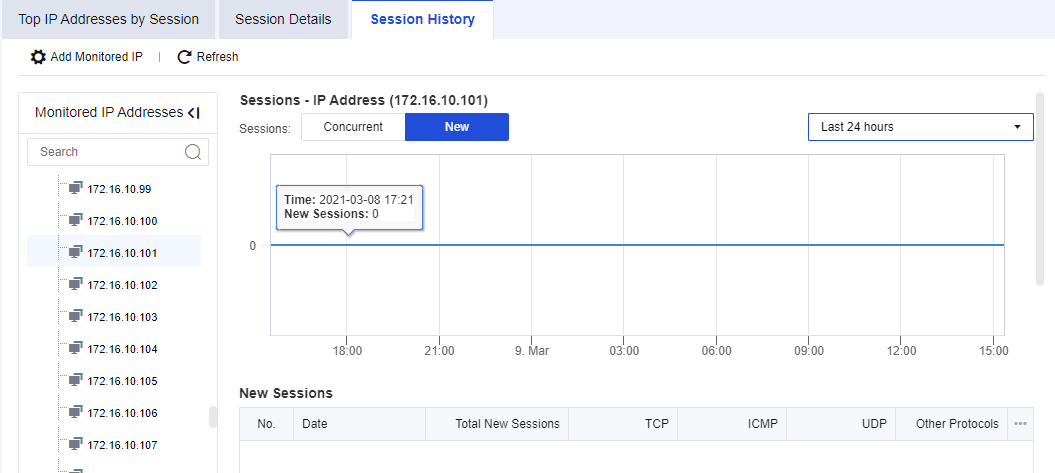
Click Add Monitored IP. You can manually enter the specified IP addresses or import an IP group, as shown in the following figure.
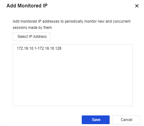
Bandwidth Management
The Bandwidth Management page appears after you enable the bandwidth management system. It displays the bandwidth channel and WAN throughput of the system, as shown in the following figure.
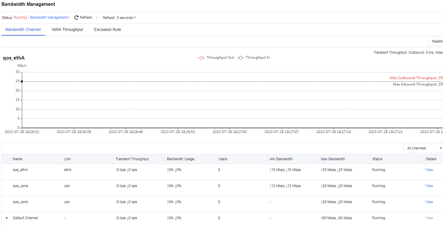
Statistics
Statistics are used to count the traffic data of services, and to identify applications based on service traffic to classify and rank the application categories. In this way, it is possible to quickly discover which applications exist in services, and view the details of traffic triggered by these applications.
Application
Application statistics are used to identify and rank the applications based on corresponding service traffic. For example, it is possible to determine which application LAN users access most frequently. The Application page is as shown below.
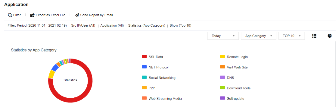
Application Statistics Query Case
An administrator needs to perform statistical analysis on the traffic of applications in a particular enterprise network to know which applications occupy the higher bandwidth.
- Click Filter to perform application filtering according to needs, as shown in the figure below.
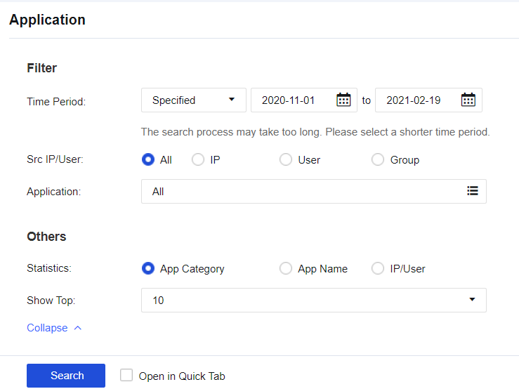
- View the query results that list which applications have the highest number of behaviors, as shown in the following figure.
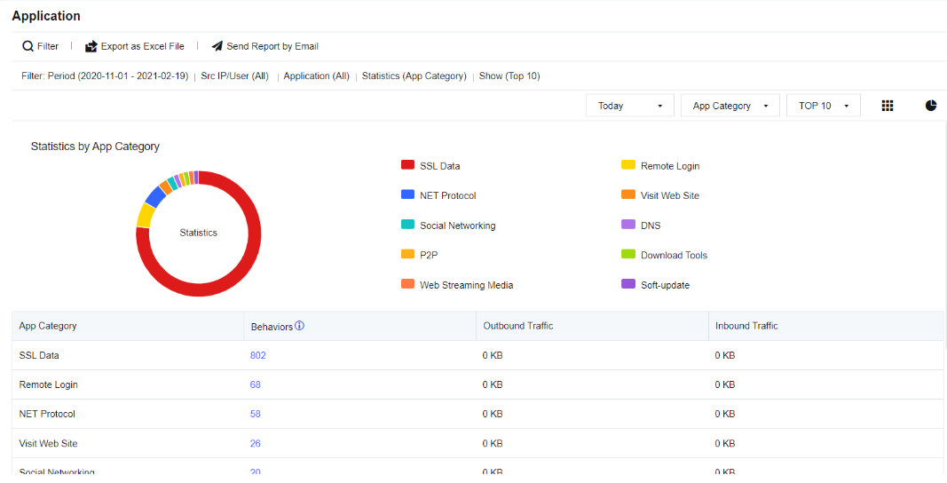
- Click Behaviors to view the application control logs triggered by the application.
Note:
It is necessary to enable the Log events function for Policy under Application Control Policy to log the application statistics.
Traffic
Traffic statistics are used to count application traffic and perform ranking based on the traffic triggered by applications. In this way, it is clearer to see which application triggers the most traffic and which one triggers the least, and quickly distinguish which traffic is generated in the service.
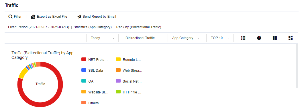
Case of Viewing Traffic Statistics
An administrator in an enterprise needs to check the proportion of applications in service traffic frequently. The administrator sees that the Web streaming media applications use more traffic, and it is necessary to make an analysis.
- Click Filter and set the filter conditions according to needs, as shown in the following figure.

- Check the results, including App Category, Outbound Traffic, Inbound Traffic, Bidirectional Traffic, etc., as shown in the following figure.
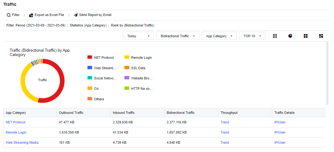
- Click Web Streaming Media to view the proportion of specific applications and traffic volume, as shown in the following figure.
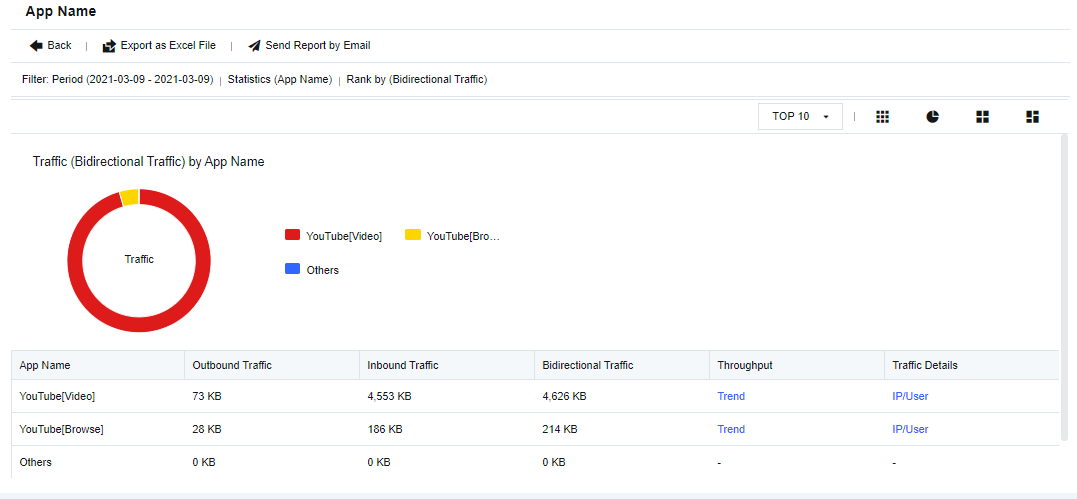
- Click Trend to view the specific traffic trend chart, as shown in the following figure.
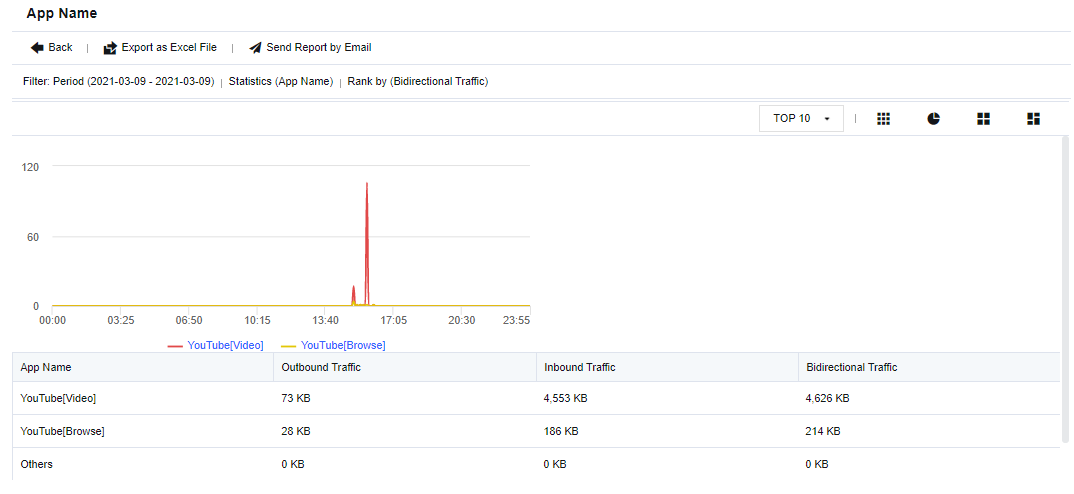
- Click IP/User to view the specific IP address or user accessing the application, as shown in the following figure.
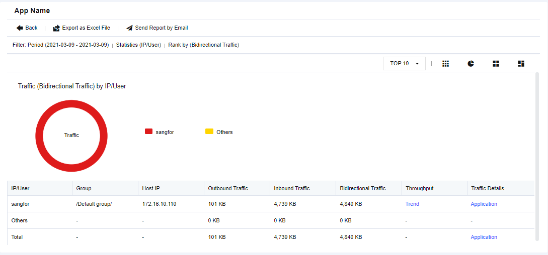
Note:
Steps to enable the traffic statistics function:
- Check the WAN attribute option in the corresponding interface.
- Enable the Traffic Audit Logs on the Monitor > Settings > Logging Options page.
Report
To set custom reports and perform report subscriptions. Two submodules are provided: Security Report and Report Subscription.
Security Report
To analyze specific business systems and end-users, and perform security risk analysis on specific objects. As shown in the figure below, the newly added Advanced options of Security Report include Show Top, Vulnerability Analysis, Block Rate, Security Rating, Report Name, Report Summary, and Logo in Report.
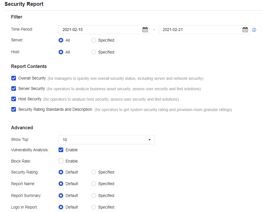
Report Subscription
To generate a report and send it to the designated email addresses periodically. The Advanced options allow to change the Show Top, Vulnerability Analysis, Block Rate, Security Rating, Report Name, Report Summary, and Logo in Report of the report. See the figure below.
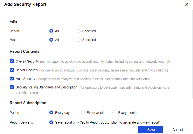
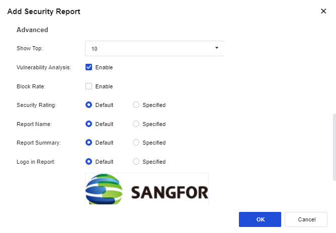
Report Generation/Deletion Settings: Set Generation Time and other parameters for the report, as shown in the following figure.

Diagnosis
Diagnosis is a feature used for checking packets that pass through the firewall. You can use it to trace packets.
Packet Tracing
Packet Tracing allows you to check packet processing flows and identify reasons for packet loss, as shown in the following figure.

Set analysis conditions and click Analyze, the details of packets will appear, as shown in the following figure.
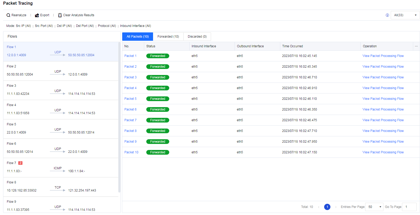
If discarded packets exist, a red icon with the number of discarded packets appears, as shown in the following figure.
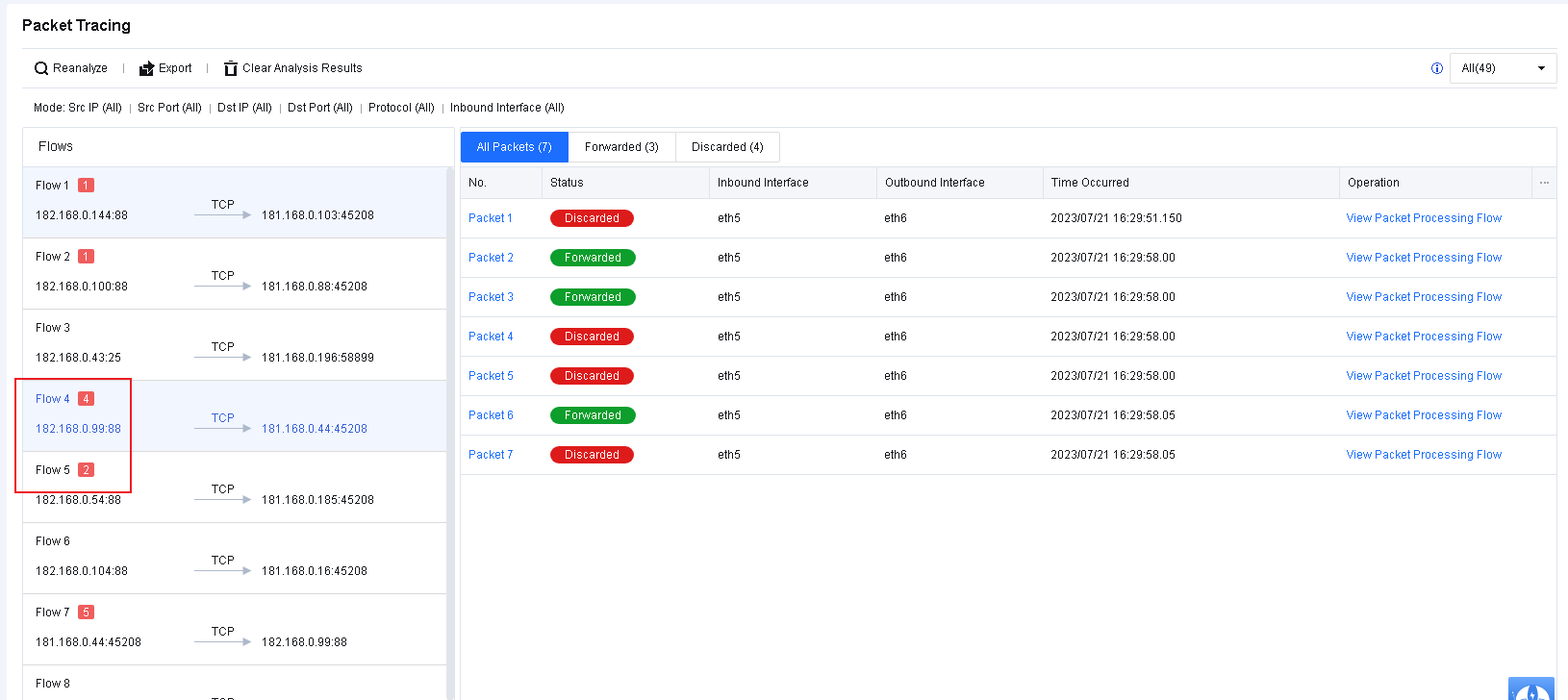
To view how a packet is processed by each firewall module, click View Packet Processing Flow. For a discarded packet, you can view where and why it is discarded, as shown in the following figure.
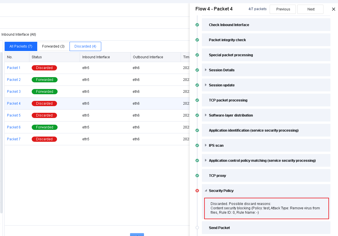
Settings
To set the log storage function and alert configuration for logs. It is a set of log function switches.
Logging Options
To enable and disable logs, and control logs generated by the device to be stored on third-party devices, to meet the compliance requirements of log storage. The Logging Options page is as shown below.
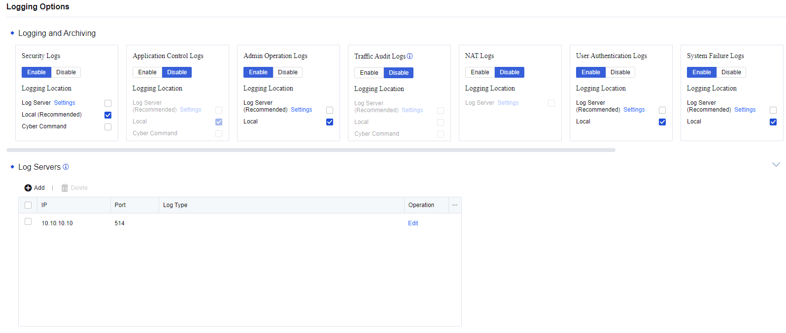
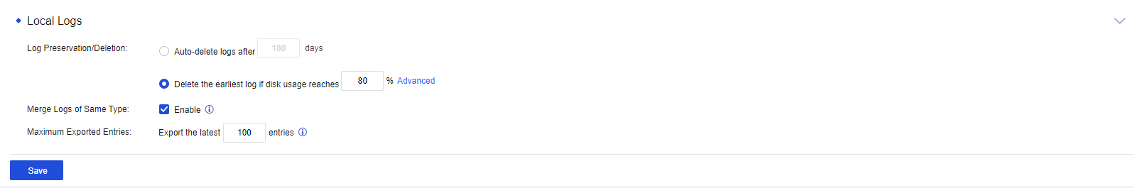
Enable Logging
After the logging function is enabled, the device can create logs on specific locations, such as Syslog, firewall, and Cyber Command. Nine types of logs can be created, including Security Logs, Application Control Logs, Admin Operation Logs, Traffic Audit Logs, NAT Logs, User Authentication Logs, System Failure Logs, SSL VPN Logs, Local ACL Logs, and INP Audit Logs. Some types of logs are disabled by default. Check the corresponding options on the page to enable logs as needed. The page is shown as follows.
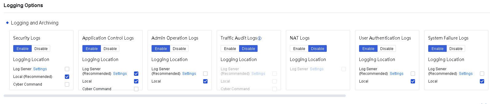
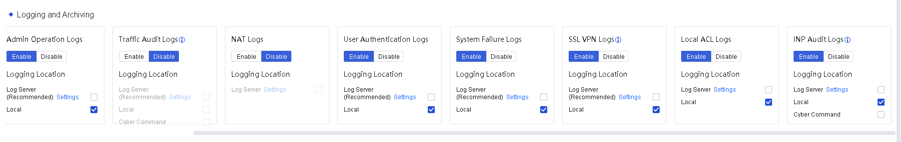
By default, it is recommended to enable Security Logs only and store the logs locally. You can make changes to enable other logging functions according to actual needs. A large amount of data will be generated when performing application control logging, traffic audit logging, NAT logging, or local ACL logging. If these logging functions need to be enabled, it is recommended to use a third-party storage device to store logs.
Note:
The INP audit log module has requirements for device hardware specifications and requires at least 8GB of memory to support it.
Log Servers
During the operation of the security device, a large number of system, security, and running logs will be generated. However, the security device’s storage space is insufficient for log storage, which tends to cause logs to be overwritten or lost, thus making it impossible to perform attack traceability analysis and meet regulatory requirements. Therefore, after the security device is successfully connected to the Syslog server, the security device sends logs to the Syslog server, thereby relieving the log storage pressure on the security device and meeting regulatory compliance requirements.
Syslog is used to send logs generated by the device to the Syslog server for storage. IP address and port details of the Syslog server need to be set.
Syslog Configuration Case
An enterprise deployed a Network Secure device at its Internet port. To meet the regulatory requirements, the security logs need to be sent to a log server for storage, and the server can only receive UDP packets on port 514.

- Enable Security Logs and send them to the log server in the form of syslog, as shown in the following figure.
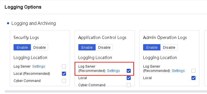
- Click Settings to enter the Application Control Logs Server Settings dialog box. Add a log server, and select a minimum log level, as shown in the following figure.
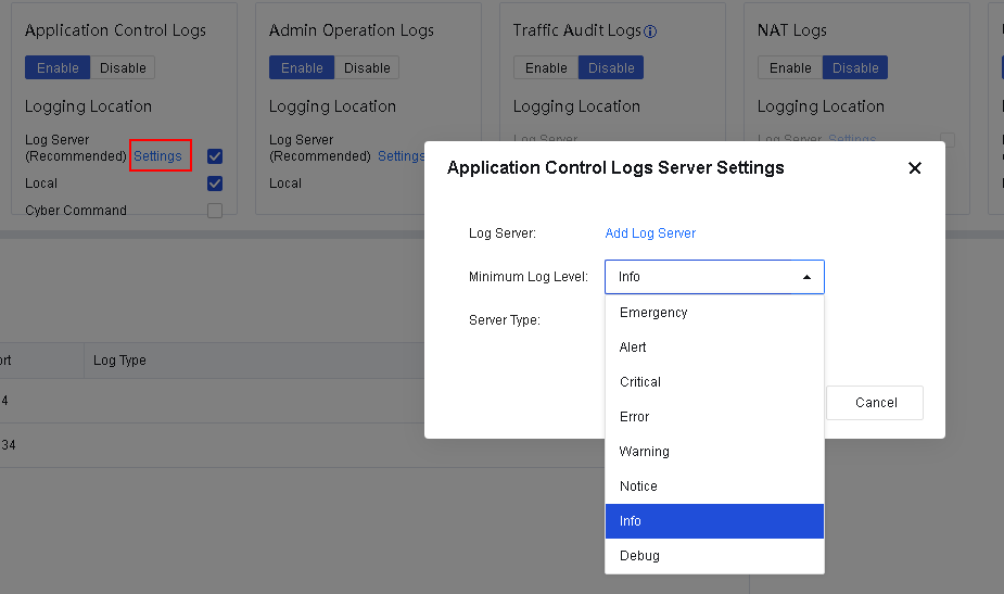
- Click Add Log Server to configure log servers. On the Log Servers page, click Add, set Port to 514, and select Security Logs for Log Type. You can configure multiple log servers, as shown in the following figure.
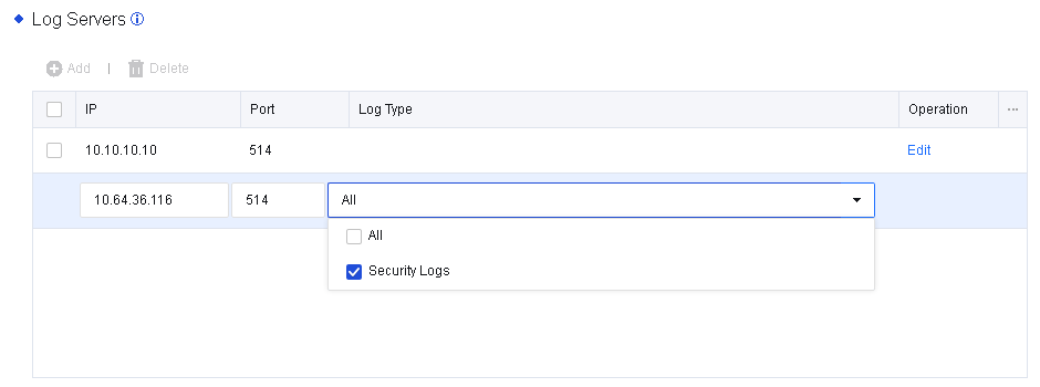
- View the security logs generated by Network Secure and select the logs that you want to send to the log server, as shown in the following figure.
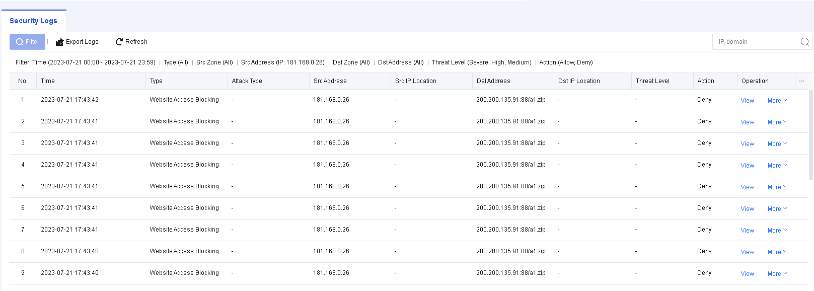
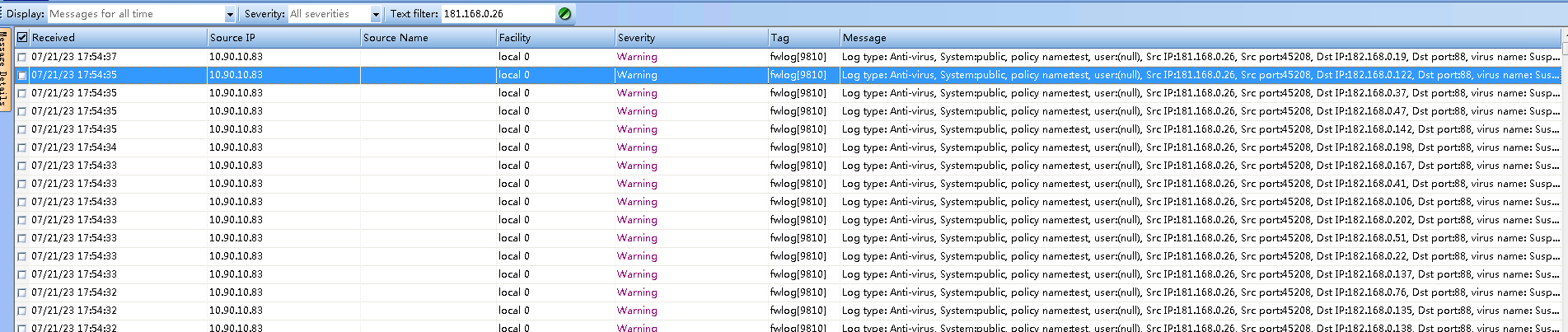
- Send the logs to the log server.
Notice:
- You can only use UDP connection and UTF-8 encoding for sending syslog.
- You can configure up to five syslog servers.
Local Logs
To set the automatic deletion options of the device for log storage, as shown in the following figure.
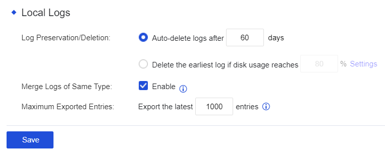
Log Preservation/Deletion: Set whether the system needs to automatically delete the access control logs recorded by selecting Auto-delete logs after xx days. You can set a duration within which logs should be preserved. By selecting Delete the earliest log if disk usage reaches xx, you can preserve logs according to the disk usage percentage.
Notice:
Deleted logs cannot be retrieved. It is recommended that Syslog, Cyber Command systems, etc., be added for log backup.
Merge Logs of Same Type: After checking Enable, the built-in data center only records one activity of access to the same domain name to save the device’s disk space.
Maximum Exported Entries: The number of logs allowed to be exported. Exporting too many logs will consume a large number of resources, such as memory and CPU.
Cyber Command Settings
This function establishes a connection between the Network Secure and CCOM systems as well as the full traffic threat analysis system. After establishing this, logs created by the Network Secure device will be synchronized with the CCOM platform, and the CCOM platform will perform further traceability analysis on the logs. The CCOM platform can also issue commands to the Network Secure device, which will execute the corresponding actions after receiving the commands.
To configure the settings for establishing the connection between the Network Secure and the CCOM system, navigate to Monitor > Settings > Logging Options. In the Logging and Archiving section, check the box next to Cyber Command for Security Logs. The Cyber Command Settings section will appear, as shown in the following figure.
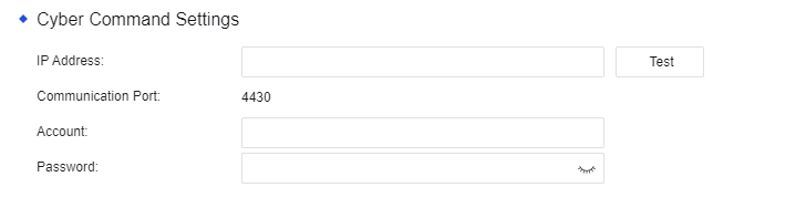
IP Address: The IP address of the CCOM system and the full traffic threat analysis system.
Communication Port: Port 4430 by default. Other ports are not currently supported.
Account: The account used to establish the connection to the CCOM system and the full traffic threat analysis system.
Password: The password used to establish the connection to the CCOM system and the full traffic threat analysis system.
Top N Options
When enabled, you can configure related settings in Monitor > Settings > Top N Options.
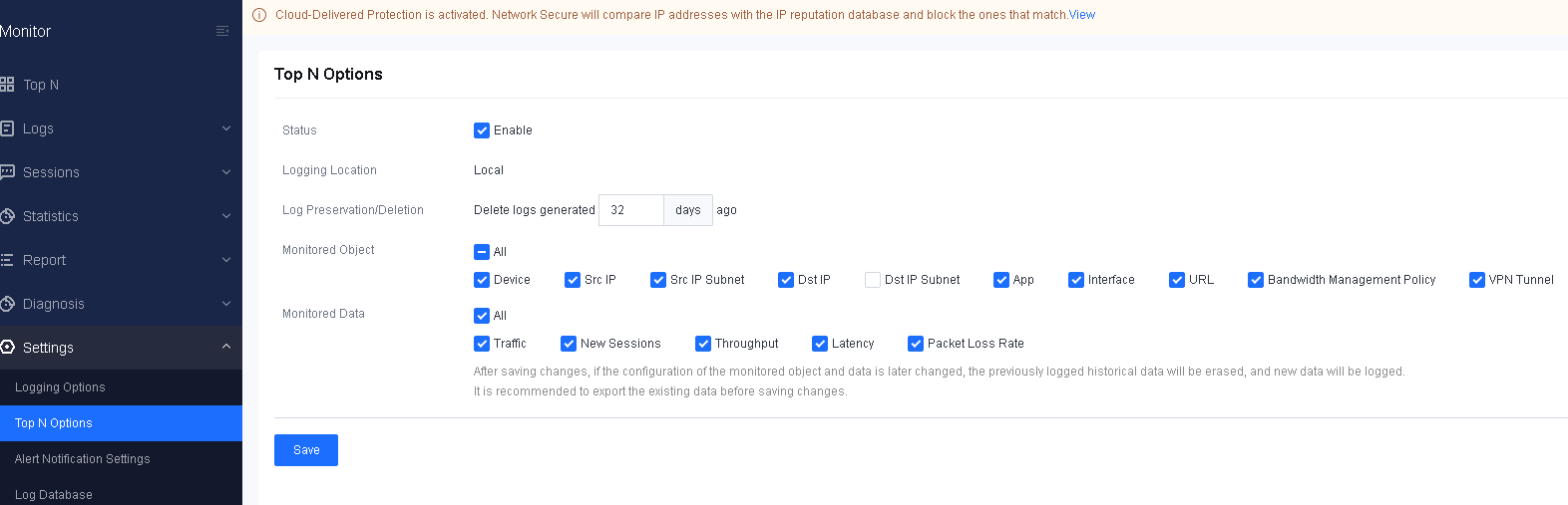
Alert Notification Settings
When abnormal behaviors of the device occur or there is an attack, alerts will be sent via emails and text messages, ensuring customers perceive the current network conditions.
Event Settings
Select the events for which the alerting function needs to be enabled. Check the boxes corresponding to events to enable the function, as shown in the following figures.
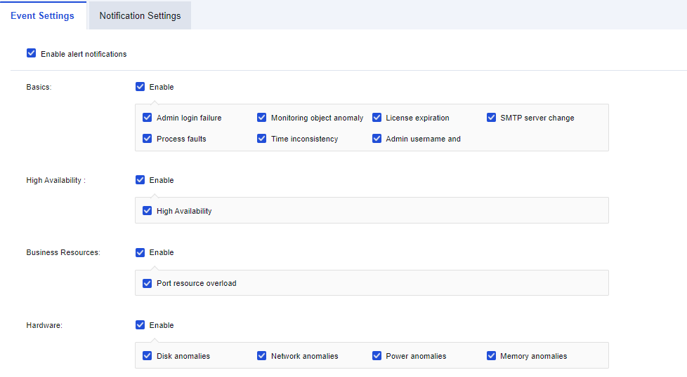
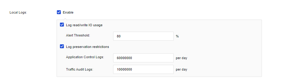
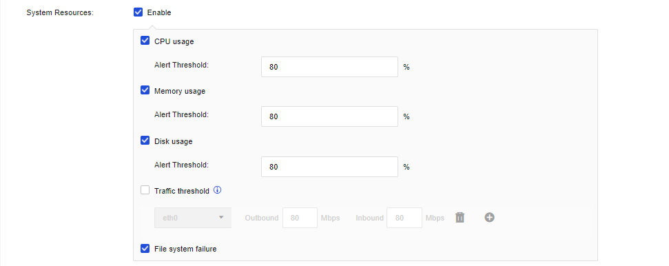
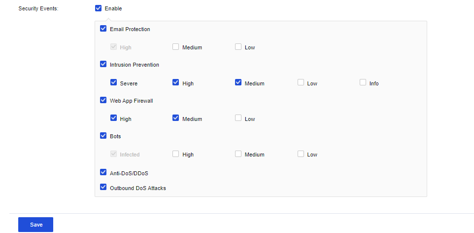
Notification Settings
Issue alerts against the events that trigger the alerts according to the set notification mode. At present, email and SMS alerts are supported, as shown in the following figure.
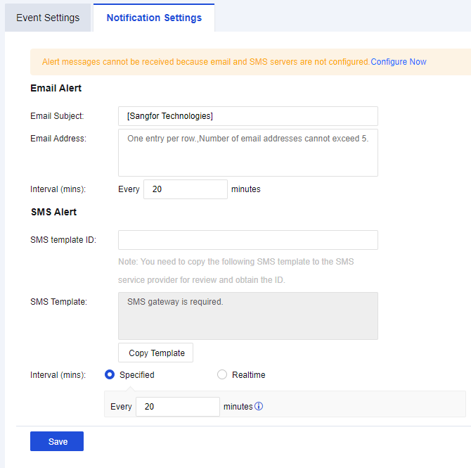
Email Alert
Configure Email Alert to send alerts via emails to an administrator’s mailbox. For example, when viruses spread through the LAN or the disk space and are used to a certain percentage, the device automatically sends alert emails to the administrator’s mailbox. Click Email & SMS Server Settings to set the Email & SMS Server.
Email Alert Setting Case
An enterprise deployed a Network Secure device at its Internet port. Email alerts against high-severity security events are required so that the administrator can respond quickly.
- Ensure the Network Secure device can access the Internet. Navigate to System > General Setttings > Email & SMS Server. Configure the Email & SMS Server as shown in the following figure.
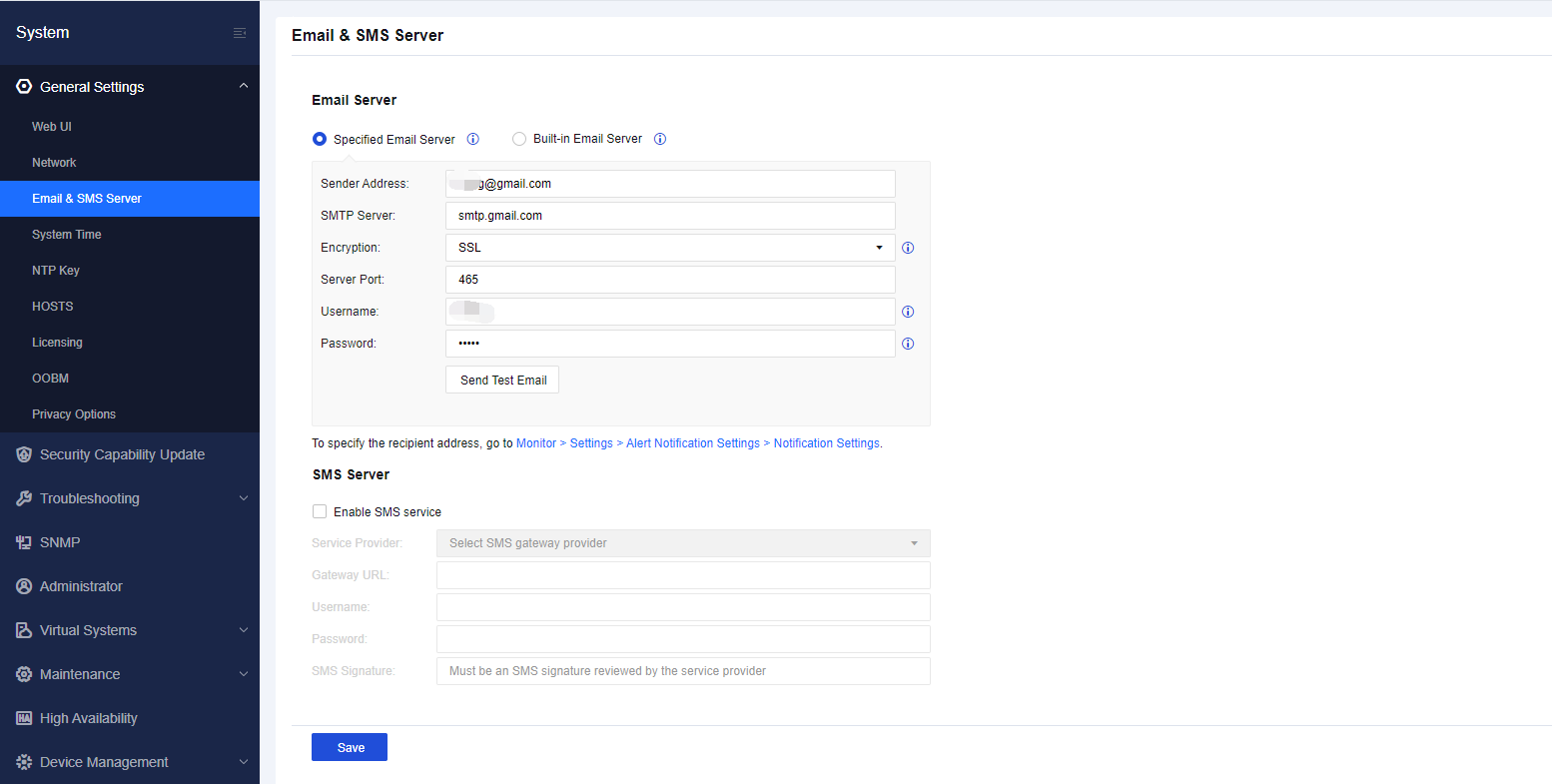
Notice:
If an authorization code for third-party clients has been activated for the configured Sender Address, enter the authorization code in the Password field.
- Navigate to Monitor > Settings > Alert Notification Settings and enable the alerting function. For Security Events, only check the High and Severe options, as shown in the following figure.
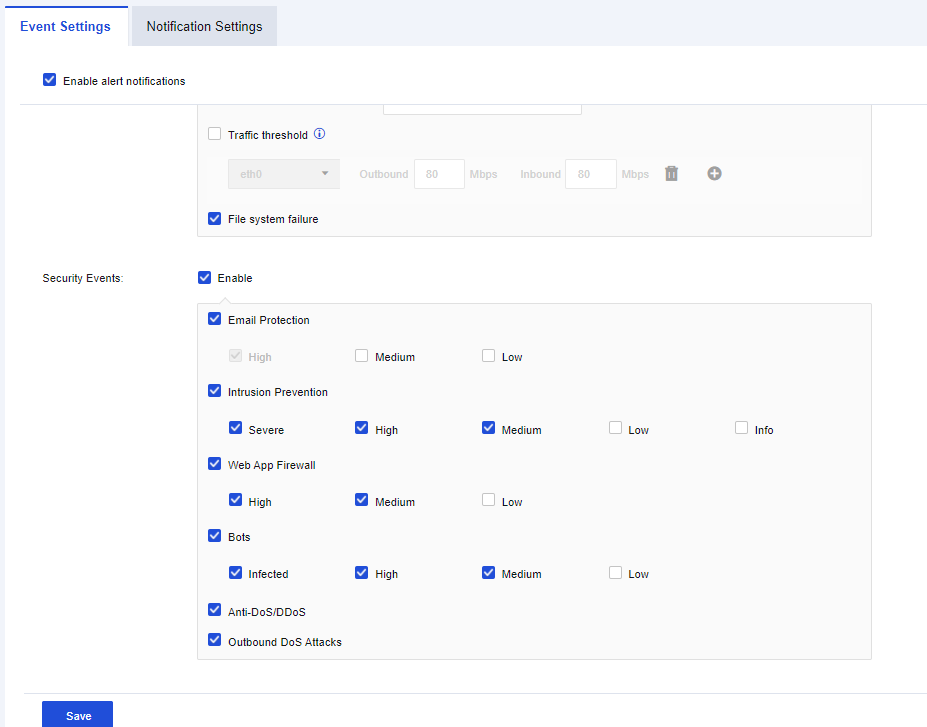
-
Set Email Alert and fill in the corresponding mailbox.
-
Check the alert details received after being attacked, as shown in the following figure.
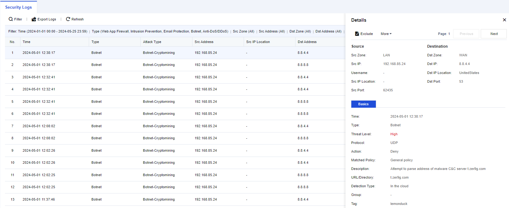
Log Database
This function is to search for the data size of log files within a specified period.
Set the date range for log searching, and click Search. The device will list the searched logs for the specified date range, as shown below.
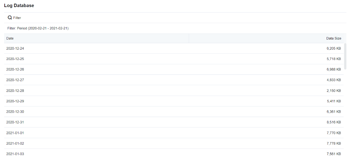
Policies
Policies serve as the main functional modules of the device and provide a complete security defense system to ensure that there are no shortcomings in security protection. The data packets being transmitted over the device are detected and controlled according to the policies. Functional modules include access control, network address translation, security policy, decryption, bandwidth management, authentication, custom web pages, etc.
Network Address Translation
The Network Address Translation (NAT) module supports source network address translation (Static NAT) and destination network address translation (Dynamic NAT), implementing network communication by translating LAN addresses into Internet addresses. It can perform destination NAT to map the access from a WAN address to a LAN address. It also enables mapping access to an Internet address to multiple IP addresses in a LAN to implement load-balancing access to LAN servers. The destination port translation is also supported. Four functional modules are provided, including IPv4 NAT, IPv6 NAT, NAT64 Translation, and DNS-Mapping.
IPv4 NAT
IPv4 NAT is applied for IPv4 environments to perform NAT translation for IPv4 addresses, including Source NAT, Destination NAT, and Bidirectional NAT. Administrators can perform the following IPv4 NAT operations.
| Operation | Note |
|---|---|
| Delete | Delete the checked policy. |
| Enable/Disable | Enable or disable the checked policy. |
| Move To | Move the position of policies to adjust the priority. The policy that topped the list has the highest priority. |
| Reset Hit Count | Clear the matching data of the selected policy and return it to 0. |
| Test Policy Match | Simulate the source and destination data packets to see whether they match the relevant policies. |
| Import/Export | Support policy import or export. |
| Refresh | Refresh the page to display the latest data. |
| Search keywords | Search by policy name. |
Table 11: IPv4 NAT Operation Options
The following topology is used in all examples in this section: The LAN user-side network segment is 192.168.1.0/24, the server-side network segment is 172.16.1.0/24, Network Secure is deployed at the internet egress as a gateway, the IP address of ETH1 interface is 1.2.1.1/24, and the IP address of ETH2 interface is 10.10.10.1/24, as shown in the following figure.
Source NAT
To translate the source IP address of data that meets translation conditions. In the most common scenarios, when the device is deployed at the internet egress and acts as a proxy for LAN users to access the internet, you must add a SNAT policy to translate the source IP address. On the IPv4 NAT tab, you can manage, add, or delete an SNAT policy. The SNAT process is shown in the following figure.
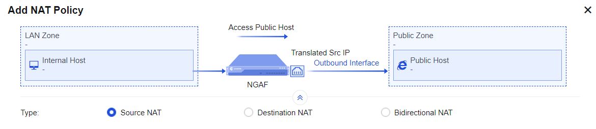
Configuration Example
If an enterprise needs to enable both LAN users and server groups to access the internet through Network Secure, you must add a SNAT policy on the Network Secure device. In this way, when data that is generated by accessing the internet through the network segments192.168.1.0/24 and 172.16.1.0/24 passes through Network Secure, its IP address can be translated into 1.2.1.1, the IP address of the Network Secure device’s egress interface ETH1.
- Define LAN and WAN zones. Before you add an SNAT policy, navigate to Network > Zones and select the zone to which the interface belongs on the Zones page. Then, navigate to Objects > Network Objects and select the IP address group to which the LAN segment belongs. In this example, select WAN for the ETH1 interface and LAN for the ETH2 interface, and define the network segments 172.16.1.0/24 and 192.168.1.0/24 as Internal on the Network Objects tab.

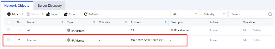
- Add a NAT policy. Navigate to Policies > NAT > IPv4 NAT and click Add. Then, the Add IPv4 NAT dialog box appears. By default, Source NAT is selected. In the Basics section, enter the name of the policy in the Name field, enter a custom description in the Description field, and specify the Position and Schedule parameters.

- Set an Original Data Packet to comply with the policy.
-
Src Zone and Src Address: Select the source IP address for which an SNAT policy is added. This is because only data from the specified source zone and specified source IP address can match this policy to enable SNAT. If the routing interface acts as a proxy for LAN users to access the internet, you can set the Src Zone parameter to LAN and the Src Address parameter to Internal or All. In this example, select LAN for the Src Zone parameter and Internal for the Src Address parameter.
-
Dst Zone/Interface and Dst Address: Set destination data that complies with the policy, such as data to the specified destination zone, accessing the specified destination IP address group, and outgoing from the specified interface. If the routing interface acts as a proxy for LAN users to access the internet, you can set the Dst Zone/Interface parameter to WAN and the Dst Address parameter to All. In this example, select WAN for the Dst Zone/Interface parameter and All for the Dst Address parameter.
-
Services: Set this parameter if SNAT is set only for the data conforming to the specified protocol, source port, and destination port. To set this parameter, click the drop-down list. In this example, you do not need to set this parameter, and any is selected by default.
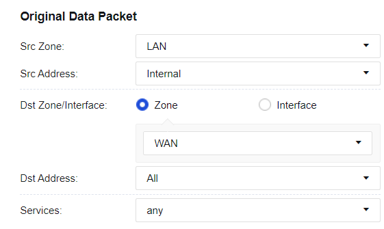
- Set a Translated Data Packet. If you select Source NAT for Type, set a specified IP address to which the source IP address of data conforming to the specified source IP address, destination IP address, and service is translated. You can select Outbound Interface, IP Range, IP Address, Network Object, or Untranslated for the Translate Src IP To parameter. In this example, select Outbound Interface from the drop-down list.
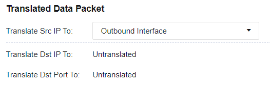
- Mode: You can set the Mode parameter to Dynamic NAT or Static NAT after selecting an IP range.
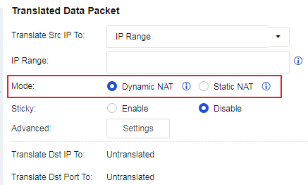
- Sticky: You can configure the sticky mode after selecting an IP range or network object. The sticky NAT escape feature ensures traffic continuity in case of port request failure through sticky NAT by requesting ports from the configured IP addresses. When entering the escape mode, an alert log will be generated to notify you that the current network environment has entered the sticky NAT escape mode. Two escape modes, Strict Mode and Loose Mode, are supported. When in Strict Mode, packets with the same source IP address are assigned the same IP address because the source IP addresses of the packets serve as the keys for IP address querying from the IP range or IP object. However, in the event of port resource request failure, an error log is printed, and the "droplist" process starts. When in Loose Mode, in the event of port resource request failure through sticky NAT, Network Secure moves forward from the failed IP address (a.b.c.d) to the next IP address within the configured IP range for requesting a port. If the port request succeeds, the resource is returned; if the port request fails, Network Secure proceeds to the next IP address to request a port until the last IP address in the configured IP range is reached. If no port is available after Network Secure proceeds to the last IP address, Network Secure moves backward from the failed IP address (a.b.c.d) to the previous IP address for requesting a port. If the port request succeeds, the resource is returned; if the port request fails, Network Secure proceeds to the previous IP address to request a port until the first IP address in the configured IP range is reached. If no port is available from all IP addresses in the IP range, an error log is printed, and the "droplist" process starts.
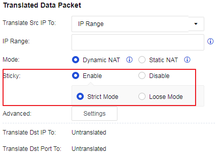
- Advanced: You can configure advanced settings after selecting an IP Range, IP Address, or Network Object.
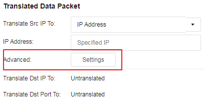
You can click Settings to enable or disable Port Pre-allocation, as shown in the following figure.
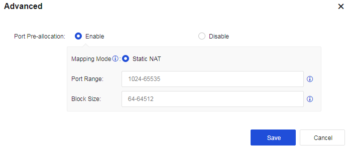
- Save the configuration. Finally, click Save. Then, the configuration of the SNAT policy is complete.
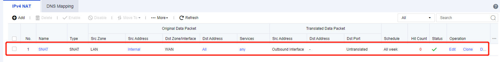
- After the application control strategy from the LAN to the WAN is allowed, use a PC in the LAN segment to normally access the WAN.
Destination NAT
To translate the destination IP address of data passing through the device. This function is often used to publish servers by mapping the services of LAN servers to the internet so that internet users can access internal servers through the public IP address. The following figure shows the destination NAT process.
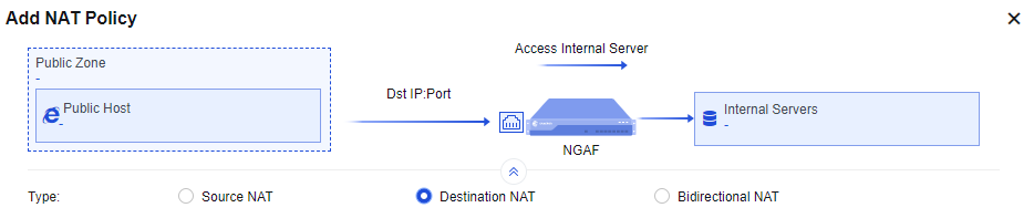
Configuration Example
There is a web server 172.16.1.100 on port 80 of an enterprise’s intranet to provide HTTP service and has applied for a domain name www.xxx.com to point to 1.2.1.1. The customer hopes that external users can enter http://www.xxx.com to access the LAN 172.16.1.100 server.
- Define LAN and WAN zones. Before you add a DNAT policy, navigate to Network > Zones and select the zone to which the interface belongs on the Zones page. In this example, select WAN for the ETH2 interface and LAN for the ETH1 interface.

- Add a NAT policy. Navigate to Policies > NAT > IPv4 NAT and click Add. Then, the Add IPv4 NAT dialog box appears. Select Destination NAT and enter the name of the policy in the Name field, enter a custom description in the Description field, and specify the Position and Schedule parameters in the Basics section.
- Set an Original Data Packet to comply with the policy.
Src Zone: Specify the zone from which the data entering the device is subject to DNAT. For example, when a LAN server is published to the internet, internet users can access the server, and this parameter is set to WAN.
Src Address: Specify the source IP address only from which data to be subject to DNAT comes.
Destination: Specify the IP address that DNAT is performed when internet users access this address. The destination IP address is the IP address accessed by users before DNAT for a data packet and is usually the public IP address of a device interface. In this example, this parameter is set to 1.2.1.1.
Services: Set the service for which DNAT is to be performed. In this example, select http (TCP:80) for this parameter. The service can be added directly or defined in the Network Objects.
- Set conditions of a Translated Data Packet.
IP Address: Specify the IP address to which the destination IP address is translated and choose whether to translate the destination port. In this example, set the IP address of the LAN server that provides HTTP services to 172.16.1.100, the Translate Dst IP To parameter to IP Address, and the Translate Port To parameter to Untranslated.
Notice:
If you need to map port 80 in the network segment 1.2.1.1 to port 8080 of the servers in the LAN segment 172.16.1.100, you can set Translate Port To to port 8080.
- Allow an application control policy. By default, Add ACL policy automatically is selected for the Allow parameter. This function automatically allows all traffic matching this policy to pass at the application control level. If this option is not selected, you need to configure the application control policy to enable the traffic to pass. Finally, click Save. Then, the configuration is complete. See the figure below.
- External users can access the LAN server 172.16.1.100 via http://www.xxx.com.
Bidirectional NAT
To translate the source IP address and destination IP address of data passing through the device. This function is often used to publish servers by mapping the services of LAN servers to the internet so that external and internal users can access internal servers through the public IP address. The following figure shows the bidirectional NAT process.
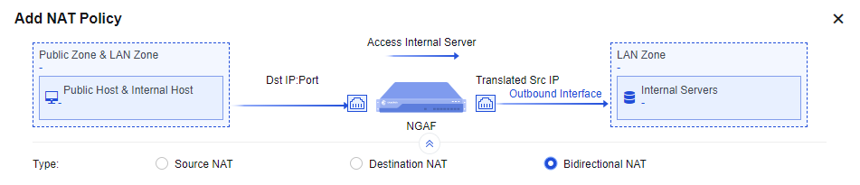
Configuration Example
An enterprise uses port 80 of a web server in the LAN segment 172.16.1.100 to provide HTTP services and has applied for a domain name www.xxx.com bound to the IP address 1.2.1.1. The customer hopes that external users can enter http://www.xxx.com to access the LAN 172.16.1.100 server, and the LAN users can also access the LAN 172.16.1.100 server by visiting http://www.xxx.com. Here, a bidirectional NAT policy is required.
- Define LAN and WAN zones. Before you add a Bidirectional NAT policy, navigate to Network > Zones and select the zone to which the interface belongs on the Zones page. In this example, select LAN for the ETH2 interface and WAN for the ETH1 interface.

- Add a NAT policy. Navigate to Policies > NAT > IPv4 NAT and click Add. Then, the Add IPv4 NAT dialog box appears. Select Bidirectional NAT, enter the name of the policy in the Name field and custom description in the Description field, and specify the Position and Schedule parameters in the Basics section.

- Set an Original Data Packet to comply with the policy.
Src Zone: Specify the zone from which the data entering the device is subject to BNAT. For example, when a LAN server is published to the internet, internet users can access the server, and LAN users can also access the server by using the public domain name. In this case, this parameter is set to WAN and LAN.
Src Address: Specify the source IP address only from which data to be subject to BNAT comes.
Destination: Specify the IP address that BNAT is performed when internet users access this address. The destination IP address is the IP address accessed by users before BNAT for a data packet and is usually the public IP address of a device interface. In this example, this parameter is set to 1.2.1.1.
Services: Set the service for which BNAT is to be performed. In this example, select http (TCP:80) for this parameter. The service can be added directly or defined in the Network Objects.
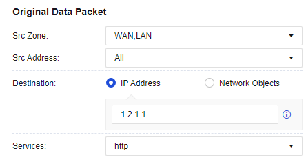
- Set conditions of a Translated Data Packet.
IP Address: Specify the IP address to which the destination IP address is translated, and whether to translate the destination port. In this example, set the IP address of the LAN server that provides HTTP services to 172.16.1.100, the Translate Dst IP To parameter to IP Address, and the Translate Port To parameter to Untranslated.
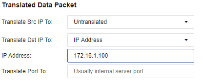
- By default, Add ACL policy automatically is selected for the Allow parameter. This function automatically allows all traffic matching this policy to pass at the application control level. If this option is not selected, you need to configure the application control policy to enable the traffic to pass. Finally, click Save. Then, the configuration is complete. See the figure below.
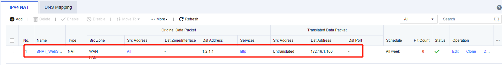
- Both external and internal users can access the server in the LAN segment 172.16.1.100 by visiting http://www.xxx.com.
IPv6 NAT
The following topology is used in all examples in this section: Both LAN and WAN segments are IPv6 network segments, the IP address of the LAN server is 2001::1/128, Network Secure is deployed at the internet egress as a gateway, the IP address of ETH1 interface is 2003::1/128, and the IP address of ETH2 interface is 2001::2/128, as shown in the following figure.
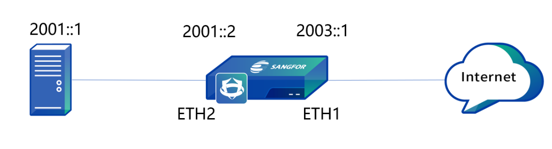
| Operation | Note |
|---|---|
| Delete | Delete the checked policy. |
| Enable/Disable | Enable or disable the checked policy. |
| Move To | Move the position of policies to adjust the priority. The policy that topped the list has the highest priority. |
| Refresh | Refresh the page to display the latest data. |
Table 12: IPv6 NAT Operation Options
Source NAT
To translate the source IP address of data that meets translation conditions. In the most common scenarios, when the device is deployed at the internet egress and acts as a proxy for LAN users to access the internet, you must add a SNAT policy to translate the source IP addresses.
IPv6 SNAT supports both LAN and WAN zones, and you can select multiple LAN and WAN zones for a source IPv6 address. You can configure the source IPv6 address and its prefix. The prefix value ranges from 4 to 128.
Configuration Example
Both LAN and WAN segments of an enterprise are IPv6 network segments, the IP address of the LAN server is 2001::1/128, Network Secure is deployed at the internet egress as a gateway, the IP address of ETH1 interface is 2003::1/128, and the IP address of ETH2 interface is 2001::2/128. If you need to hide the LAN IP address, SNAT should be used to translate the LAN IP address to the IP address of the ETH1 interface in Network Secure for internet access.
- Define LAN and WAN zones. Before you add an SNAT policy, navigate to Network > Zones and select the zone to which the interface belongs on the Zones page. In this example, select WAN for the ETH1 interface and LAN for the ETH2 interface. See the figure below.
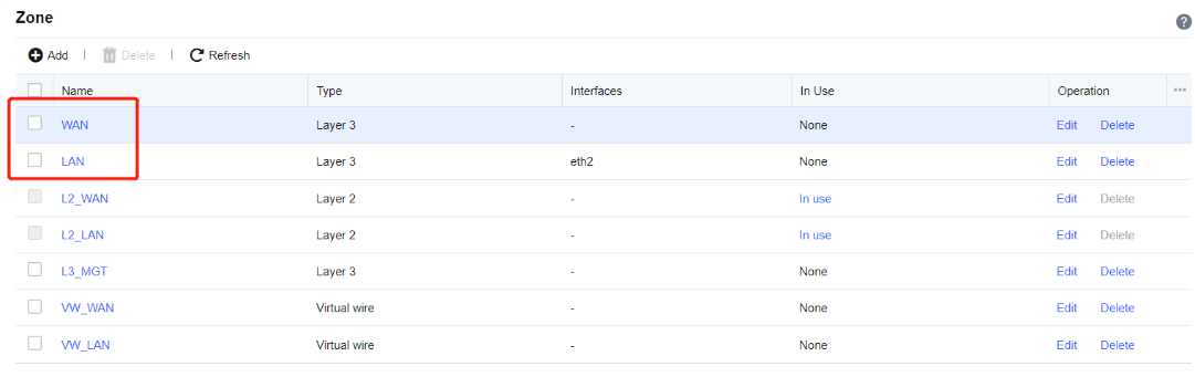
- Add an SNAT policy. Navigate to Policies > NAT > IPv6 NAT, click Add to enter the Add IPv6 NAT Policy dialog box. Select Source NAT for Type, and then enter the name in the Name field.
Src Zone: Select LAN.
Src Address: Enter 2001::1/128 for the IP address of the LAN server.
Dst Zone/Interface: Select WAN.
Dst Address: Enter 2003::1/128 for the IP address of the ETH1 interface.
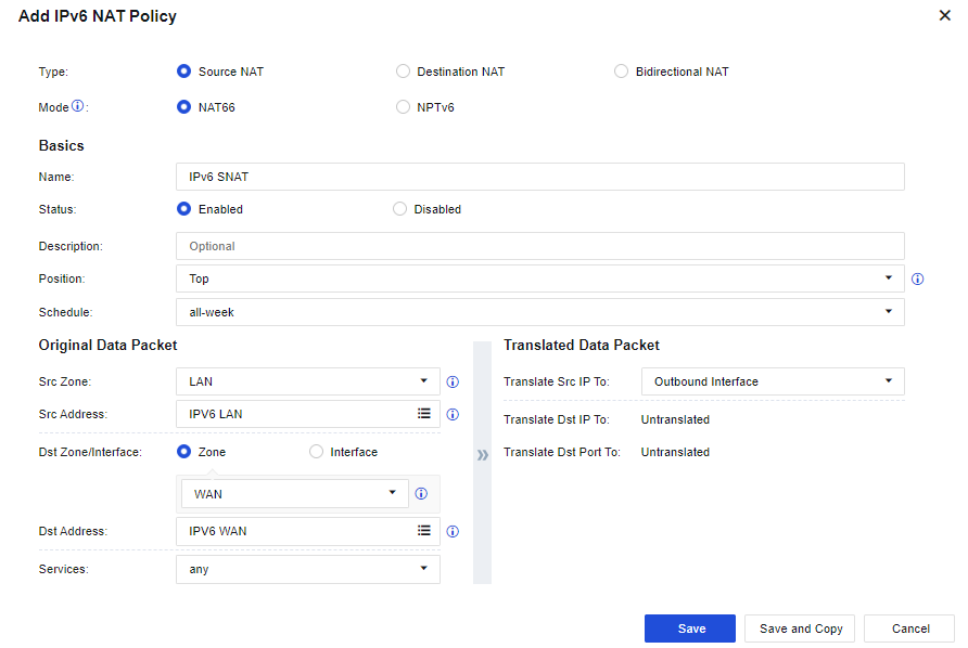
- Save the configuration. Finally, click Save. Then, the configuration of the SNAT policy is complete. See the figure below.
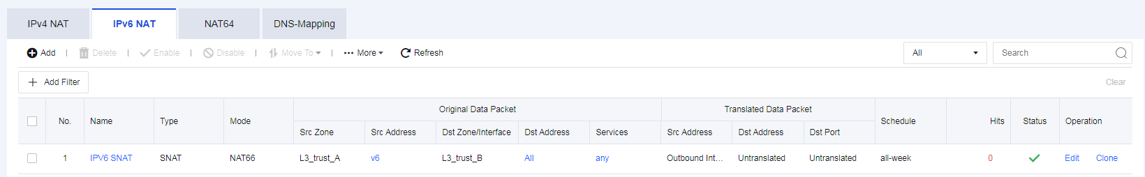
- After the application control strategy from the LAN to the WAN is allowed, use the server to access the internet by translating the source IP address to the IP address of the ETH1 interface in Network Secure.
Destination NAT
To translate the destination IP address of data passing through the device. Destination NAT is often used to publish servers by mapping the services of LAN servers to the internet so that internet users can access internal servers through the public IP address.
IPv6 DNAT supports the LAN zone and enables you to configure the destination IPv6 address and its prefix. The prefix value ranges from 4 to 128.
Configuration Example
Both LAN and WAN segments of an enterprise are IPv6 network segments, the IP address of the LAN server is 2001::1/128, Network Secure is deployed at the internet egress as a gateway, the IP address of ETH1 interface is 2003::1/128, and the IP address of ETH2 interface is 2001::2/128. If you need to use the LAN server to publish web services to the internet, internet users can access the LAN server through the IP address of the ETH1 interface in Network Secure for internet access.
- Define LAN and WAN zones. Before you add an SNAT policy, navigate to Network > Zones and select the zone to which the interface belongs on the Zones page. The following figure shows the specific configuration. In this example, select WAN for the ETH1 interface and LAN for the ETH2 interface. See the figure below.

- Add a DNAT policy. Navigate to Policies > NAT > IPv6 NAT, click Add to enter the Add IPv6 NAT Policy dialog box. Select Destination NAT for Type, and then enter the name in the Name field.
Src Zone: Select WAN.
Src Address: Enter 2003::1/128 for the IP address of the ETH1 interface.
Destination: Enter 2002:222:1/128 for the IP address of the LAN server.
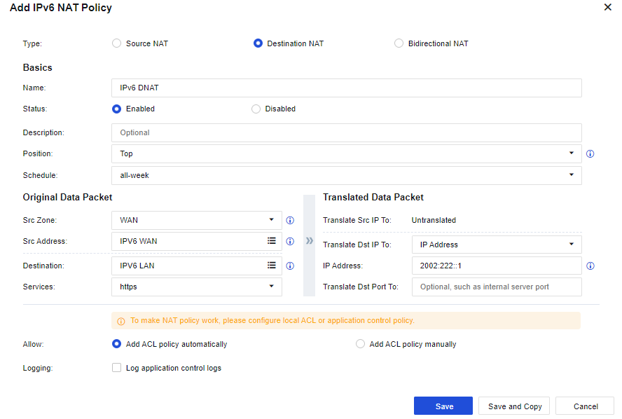
- Save the configuration. Finally, click Save. Then, the configuration of the DNAT policy is complete. See the figure below.
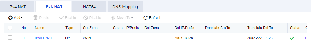
- After the application control policy for web services from the WAN to the LAN is allowed, access the LAN server by visiting http:// [2003::1] through WAN.
NAT64
For mutual access between IPv6 and IPv4 environments and provides the address translation process. This function completes data communication between the IPv6 and IPv4 protocols. At present, NAT64 only supports one-to-one NAT. The administrator can perform the following operations for such NAT.
| Operation | Note |
|---|---|
| Delete | Delete the checked policy. |
| Enable/Disable | Enable or disable the checked policy. |
| Move To | Move the position of policies to adjust the priority. The policy that topped the list has the highest priority. |
| Import/Export | Support policy import or export. |
| Refresh | Refresh the page to display the latest data. |
| Search keywords | Search by policy name. |
Table 13: NAT64 Operation Options
IPv4 to IPv6 NAT
To translate the protocol request to access the IPv4 address into the IPv6 address for communication. It allows access from the IPv4 protocol to the IPv6 protocol.
Configuration Example
The LAN of an enterprise is an IPv6 network, the IP address of the LAN server is 2003::1/128, the WAN is an IPv4 network, and the IP address of the ETH1 interface in Network Secure is 1.2.1.1/24. If you need to use the LAN server to publish web services to the IPv4 network, IPv4 network users can access the LAN server by visiting http://1.2.1.1. The detailed topology is shown in the following figure.
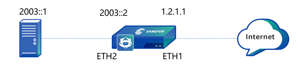
- Define LAN and WAN zones. Before you add an SNAT policy, navigate to Network > Zones, and select the zone to which the interface belongs on the Zones page. Then, navigate to Objects > Network Objects and select the IP Group to which the LAN segment belongs. In this example, select WAN for the ETH1 interface and LAN for the ETH2 interface. See the figure below.
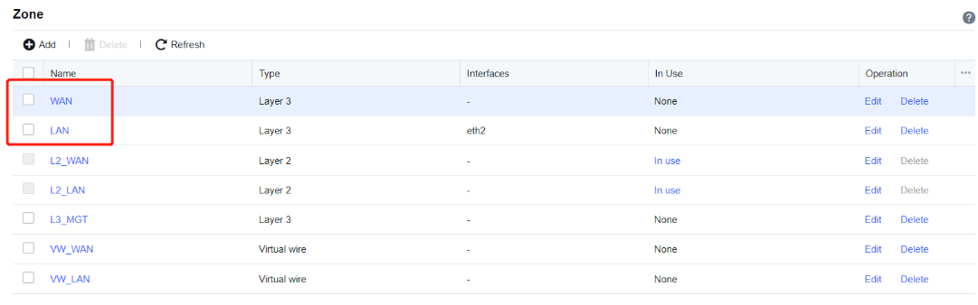
- Add an IPv4 to the IPv6 NAT policy. Navigate to Policies > NAT > NAT64, click Add, and select Add NAT Policy (IPv4 to IPv6). In the Add NAT Policy (IPv4 to IPv6) dialog box, enter the name in the Name field.
Src Zone: Select WAN.
Src Address: Select All.
Destination: Enter 1.2.1.1/32.
Services: Select http (TCP:80).
Translate Src IP To: Set the IPv6 address to the IP address of the ETH2 interface, 2003::2.
Translation Dst IP To: Set the IPv6 address of the LAN server to 2003::1/128.
Translate Dst Port To: Set if the destination port required to change.
By default, Allow matching packets, no application control policy applied is selected. See the figure below.

- Save the configuration. Finally, click Save. Then, the configuration of the IPv4 to IPv6 NAT policy is complete. See the figure below.
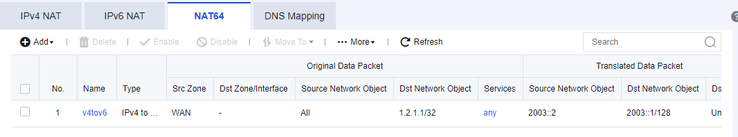
- WAN users can access the LAN server by visiting http://1.2.1.1/.
IPv6 to IPv4 NAT
To translate the protocol request to access the IPv6 address to the IPv4 address for communication. This function allows access from the IPv6 protocol to the IPv4 protocol.
Configuration Example
The LAN of an enterprise is an IPv4 network, the IP address of the LAN server is 192.168.1.2/24, the WAN is an IPv6 network, and the IP address of the ETH1 interface in Network Secure is 2003::1/128. If you need to use the LAN server to publish web services to the IPv6 network, IPv6 network users can access the LAN server by visiting http:// 2003::1. The detailed topology is shown in the following figure.
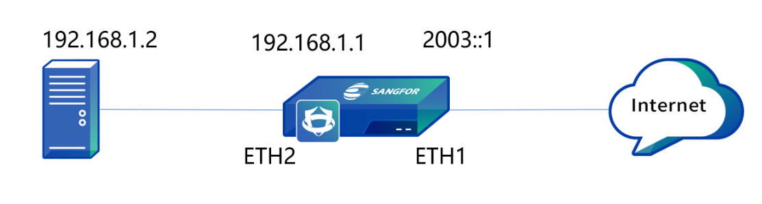
- Define LAN and WAN zones. Before you add an SNAT policy, navigate to Network > Zones, and select the zone to which the interface belongs on the Zones page. Then, navigate to Objects > Network Objects and select the IP Group to which the LAN segment belongs. In this example, select WAN for the ETH1 interface and LAN for the ETH2 interface. See the figure below.

- Add an IPv6 to the IPv4 NAT policy. Navigate to Policies > NAT > NAT64, click Add, and select Add NAT Policy (IPv6 to IPv4). In the Add NAT Policy (IPv6 to IPv4) dialog box, enter the name in the Name field.
Src Zone: Select WAN.
Sr Address: Select All.
Destination: Enter 2003::1/128.
Services: Select http (TCP:80).
Translation Src IP To: Set the IPv4 address to the IP address of the ETH2 interface address, 192.168.1.1.
Destination Translation: Set the IPv4 address of the LAN server to 192.168.1.2/32. By default, Allow matching packets, no application control policy applied is selected.

- Save the configuration. Finally, click Save. Then, the configuration of the IPv6 to IPv4 NAT policy is complete. See the figure below.
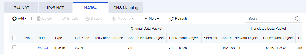
- WAN users can access the LAN server by visiting http://[2003::1].
DNS-Mapping
DNS mapping enables LAN users to access LAN servers through the domain names of the public network. This achieves the same effect as the bidirectional NAT policy. After DNS mapping is set, when a LAN user sends the DNS request, the Network Secure device actively resolves the domain name into the LAN IP address of the server and returns it to the client. The client directly accesses the LAN IP address of the server without policy-based translation.
DNS mapping differs from bidirectional NAT in the following aspects:
-
After DNS mapping is set, data generated when users access the LAN server does not pass through the Network Secure device, whereas the device directly accesses the LAN IP address of the server. While for bidirectional NAT, all access data will pass through the Network Secure device. Thus, DNS mapping can reduce the firewall load.
-
The setting method of DNS mapping is simpler than bidirectional NAT. You do not need to set the zone, IP group, or port.
Configuration Example
An enterprise has the following topology. A web server in the network segment of 172.16.1.100 exists in the LAN. The enterprise has applied for the domain name www.xxx.com that is bound to the IP address 1.2.1.1.
If you want the LAN user 192.168.1.0/24 to access the server in the network segment of 172.16.1.100 by entering www.xxx.com, you can use DNS mapping to allow LAN users to access the web server by entering the domain name.
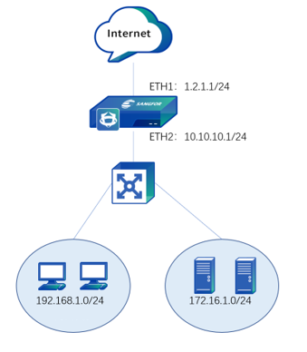
- Navigate to Policies > NAT > DNS-Mapping and click Add.
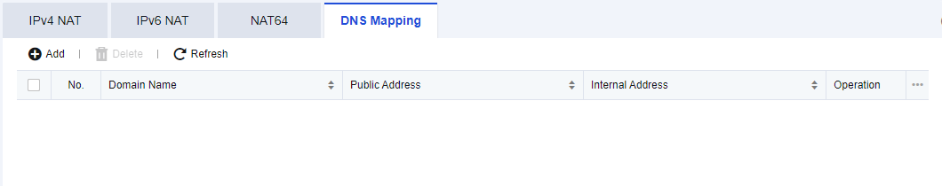
- In the Add DNS Mapping dialog box, set the Domain Name, Public IP, and Internal IP parameters. In this example, specify these parameters based on the following figure.
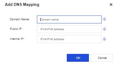
- Click OK. Then the configuration is complete. At this time, LAN users can directly access 172.16.1.100 by entering www.xxx.com.
Access Control
To control messages passing through the device by policy features. This function includes functional modules, such as application control policy, regional access control, local ACL, connection number control, web keyword detection, and protocol command control.
Application Control
For refined control of internal users’ internet access (HTTP) behavior, FTP behavior, IM behavior, tool behavior, etc. In general, an enterprise needs to manage the internet access behaviors of LAN users. Different users need different permissions to access network resources. The permissions of the same user in different periods are often different. The application control function of Network Secure can meet the above requirements.
By integrating Endpoint Secure, you can track and control applications from the endpoint application list to prevent employees from using those apps during office hours, improving productivity and reducing network security risks.
To set this module, you need to use Zones under the Network module and objects such as Services, Network Objects, Schedule, and Application Signatures database under the Objects module.
Navigate to Policies > Access Control > Application Control to go to the page to set an application control policy or endpoint app control policy. You can add, delete, enable, disable, or search for an application control policy on this page. By default, the device provides a control policy that denies all services or applications.
For the Endpoint App Control configuration guide, please refer to Chapter 4.5.5 Endpoint App Control.
Policy Configuration
To add, modify and adjust the application control policy. Select the checkbox next to the priority number to perform the corresponding operation on the policy group.
| Operation | Note |
|---|---|
| Delete | Delete the current policy group. |
| Edit | Edit the name of the policy group. |
| Insert Above | Insert a new policy group above the current policy group. |
| Move to Top | Move the current policy group to the top. |
| Move Up | Move the current policy group up by one position. |
| Move Down | Move the current policy group down by one position. |
| Move To | Move the current policy group to a specified position in the order. |
Table 14: Policy Configuration Operation Options
Application Control Policy:
On the Policy Configuration page, click Add. Then, the Add Application Control Policy dialog box appears. The settings are as follows.
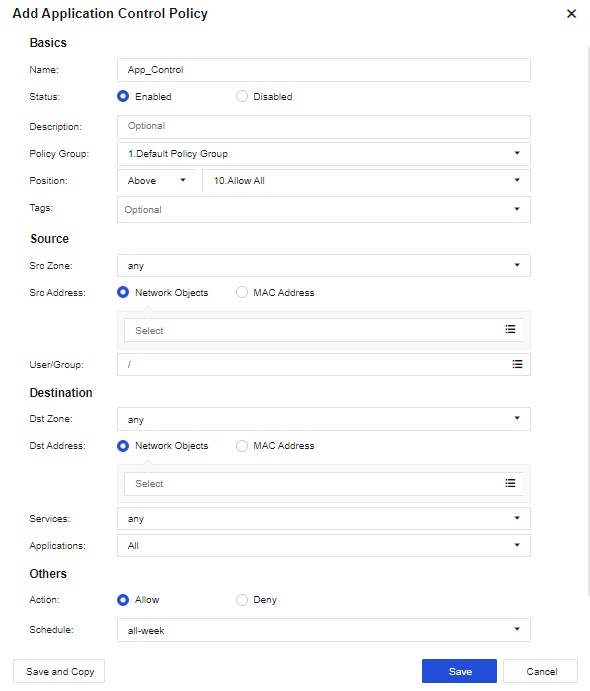
Basics:
Name: Enter a custom policy name.
Status: Set the policy status to Enabled or Disabled.
Description: Enter the description of the policy. This parameter is optional.
Policy Group: Select the policy group to which the policy belongs.
Position: Set the priority of the policy to enable it before or after a policy.
Tags: Select the policy tag. This parameter is optional and can be set for displaying a specified zone or filtering.
Source:
Src Zone: Select the source zone of the data to be controlled. By default, any is selected. It indicates that data from all zones needs to be controlled.
Src Address: Select the source Network Objects to be controlled. You may choose the MAC Address as the source address.
User/Group: Indicate user information obtained by navigating to Policies > Authentication > Local Users > Group/User.
Destination:
Dst Zone: Select the destination zone of the data to be controlled. By default, any is selected. It indicates that data from all zones needs to be controlled.
Dst Address: Select the destination IP group of the data to be controlled. To control the data of LAN users accessing the internet, select All for the Dst Address parameter.
Services: Select services that need to be controlled. Services that you can select are the ones set on the Objects > Services page.
Applications: Select applications to be controlled. Application signatures are called by going to Objects > Content Identification Database > App Signature.
Notice:
Both the Services and Applications parameters need to be filled in to match the policy.
Others:
Action: Set whether to allow or deny the data packets that meet the defined conditions.
Schedule: Indicate a filter condition. The policy can take effect only if filtering is performed within a specified point in time. The time object defined on the Objects > Schedule page is called.
Advanced: Click Settings. Then, the Advanced dialog box appears. See the figure below.
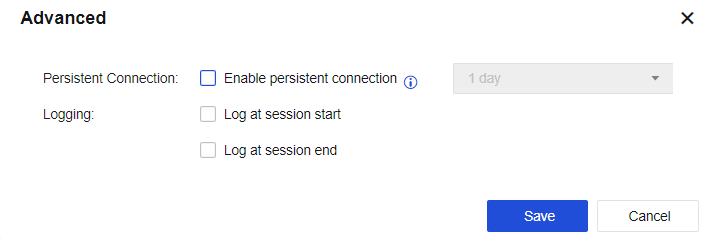
Persistent Connection: This function only supports special servers with a persistent connection request. In this case, this request is not affected by firewall timeout. If this function is enabled, the connection release slows down. The value can be 1 day to 15 days. Proceed with caution.
Logging: By default, the application control log function is not enabled. Before setting this advanced option, you need to navigate to Monitor > Settings > Logging Options, enable Application Control Logs and select the Local option to save the application control logs. Enable Logging option, Application Control logs will then be recorded on the NSF device. The large size of the application control logs will degrade the read/write performance of system disks. It is recommended that the logs be stored with an external data center or using the Syslog server.
Endpoint App Control Policy:
On the Policy Configuration page, click Add. Then, the Add Endpoint App Control Policy dialog box appears. The settings are as follows.
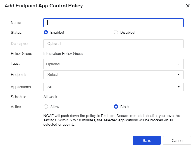
Name: Enter a custom policy name.
Status: Set the policy status to Enabled or Disabled.
Description: Enter the description of the policy. This parameter is optional.
Policy Group: The endpoint app control policy will be set in Integration Policy Group.
Tags: Select the policy tag. This parameter is optional and can be set for displaying a specified zone or filtering.
Endpoints: Select the endpoint IP to be controlled. You can create the endpoint IP according to the endpoint list in SOC > Next-Gen Security > Endpoint Protection > Endpoints.
Applications: Select applications to be controlled. Application signatures are called by going to Objects > Content Identification Database > Application Signature > Endpoint App Signature.
Schedule: Indicate a filter condition. The policy can take effect only if filtering is performed within a specified point in time. The time object defined on the Objects > Schedule page is called.
Action: Set whether to allow or deny the data packets that meet the defined conditions.
On the Policy Configuration page, click More > Settings for more configuration options, as shown in the following figure.
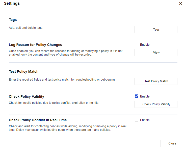
Tags: Set related tag operations, including adding, editing, and deleting tags. See the figure below.
Log Reason for Policy Changes: After this function is enabled, you can record the reasons for adding or modifying a policy. If it is not enabled, only the content and type of change will be recorded. Click View to go to the Policy Change Tracking page.
Test Policy Match: Test whether the policy matches based on the quintuple. See the figure below.
Check Policy Validity: Check invalid policies.
Check Policy Conflict in Real-Time: Check and alert for conflicting policies while adding, modifying, or moving a policy in real-time. After this function is enabled, a delay may occur while loading a page when there are too many policies.
Application Control Configuration Case
An enterprise does not allow R&D department personnel to use IM chat tools during working hours. When R&D personnel use IM tools, the device will refuse the request. To implement this function, you need to add an application control policy on Network Secure.
Operation Steps
- Navigate to Policies > Access Control > Application Control > Policies and click Add. Then, the Add Application Control Policy dialog box appears.
The relevant parameters in the Basics section can be set as follows:
Name: Enter Allow RDP.
Status: Select Enabled.
Description: Enter custom descriptions, such as personnel in the R&D Department not being allowed to use IM.
Policy Group: Select a default policy group.
Position: Set the priority before the P2P download is limited.
Tag: Enter a customizable tag or select a default one.
- Select a custom LAN zone for the Src Zone parameter. For more information about how to define a zone, see Chapter 5.2 Zones. Select a custom R&D department for the Src Address parameter. For more information about how to define a user group, see Chapter 7.6.2 Local Users.
Notice:
If the user group is selected in the current policy, you need to enable the authentication function and configure relevant authentication policies. If the authentication policy is not enabled, this application control policy will not take effect.
- Set the parameters in the Destination section. Select WAN for the Dst Zone parameter, All for the Dst Address parameter, any for the Services parameter, and Remote Login/RemoteDesktop for the Applications parameter.
- Set the parameters in the Others section: Select Allow for the Action parameter and all-week for the Schedule parameter. If you need to view the logs, click Settings and select Logging in the Advanced dialog box.
-
Click Save. Then, the configuration is complete.
-
After that, if the R&D department personnel use PCs to log in to the remote desktop, they can log in to the remote desktop normally.
-
Navigate to Monitor > Logs > Access Log to view the details of denied logs.
Policy Optimization
The policy optimization function provides tips for the current unreasonably configured application control policies by performing a systematic analysis. In the situation of many application control policies configured, this function quickly optimizes the current application control policies for fine management and control based on the principle of minimizing the scope of the traffic allowed.
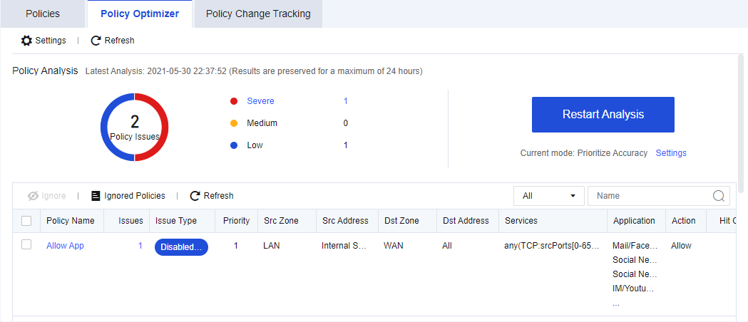
Click the Start button. Then, the system automatically performs a policy optimization analysis and generates a risk list, as shown in the above figure.
Click the Ignore button in the Operation to ignore the event and stop detecting the application control policy events in a certain period.
Click the View button in the Operation column of the policy to be optimized. Details (suggested solutions) of the policy are then displayed, as shown in the following figure:
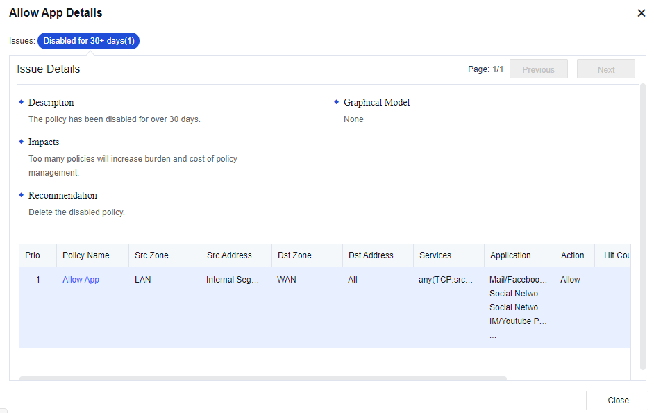
Policy Change Tracking
Policy Change Tracking operates application control policies within the specified query range, records and displays policy changes for recording and traceability of routine maintenance.

Start Time: Set the start time of the changes to be queried.
End Time: Set the end time of the changes to be queried.
Policy: Set the application control policies of which the changes are to be queried. The default setting is to query the changes of All policies.
Operation Type: Set the type of changes to be queried, including Add, Edit, and Delete.
Account: Set the accounts of which the changes are to be queried. The default setting is to query the changes of All accounts.
After you set the preceding parameters, click Search. Then, the following contents appear.
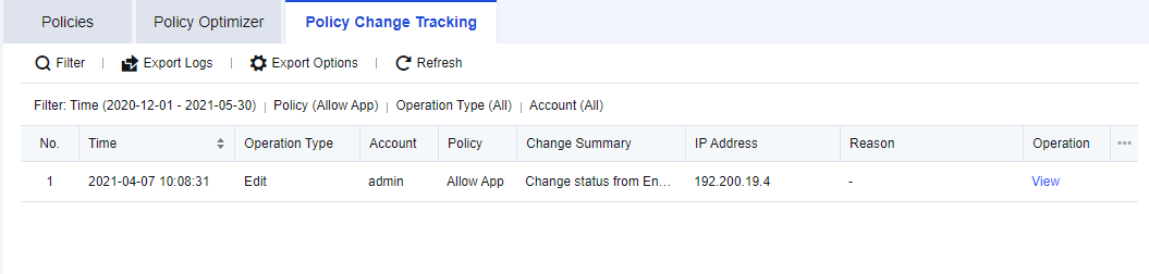
Export Logs: Export the change query results as a table in the .csv format.
Export Options: Set the content to be displayed in the exported logs. By default, all contents of a log are to be exported. You can set the items that are not to be exported as required.
Log Details: Click View in the Operation column of the change records queried. Then, the details of the changes are displayed, as shown in the following figure.
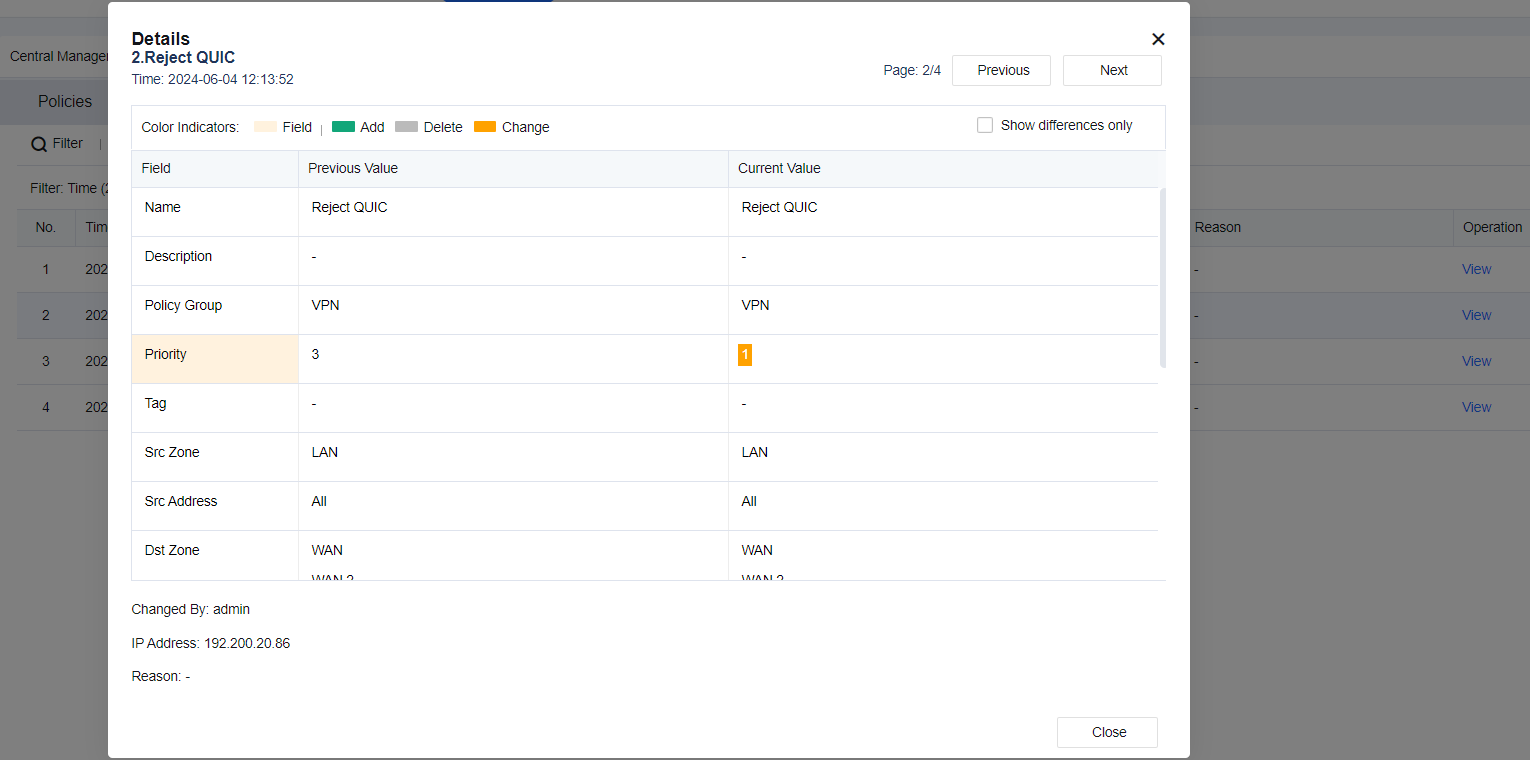
GeoLocation Blocking
To allow or deny the access of traffic of IP addresses in specified countries or regions to the LAN area protected by the Network Secure device. The administrator can perform the following operations.
| Operation | Note |
|---|---|
| Add | Add a regional access control policy. |
| Exclusion | Add IP addresses that are not subject to regional access control. |
| Blocked IP Addresses | Display the IP address records denied by the regional access control policy. |
| Location Lookup | Enter the IP address to query the corresponding location. |
| Change IP location | Manually update the ISP address library. |
Table 15: GeoLocation Blocking Operation Options
Configuration Steps
An enterprise provides a LAN server for internet users to access, but only specific to domestic services. To avoid malicious access by foreign IP addresses, you must set in Network Secure to allow only users using IP addresses from specified country/region, for example mainland China, to access the LAN server.
- Navigate to Policies > Access Control > GeoLocation Blocking and click Add. Then, the Add dialog box appears. See the figure below.
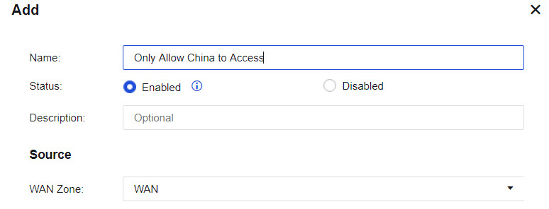
-
Enter the policy name Only Allow China to Access in the Name field, select Enable for the Status parameter, and enter a custom description in the Description field. Then, select WAN for the WAN Zone parameter in the Source section. For more information about how to define the zones, see Chapter 5.2 Zones.
-
Select a network object as the Destination. For more information about defining the network object, see Chapter 8.1 Network Objects or click Add to add it.
-
Select Allow access from specified countries/regions for the Action parameter and Asia/MainlandChina for the Country/Region parameter. See the figure below.
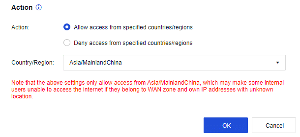
-
Click OK to save the settings. Then, the configuration is complete. In this case, only the IP addresses from mainland China can access the LAN server.
-
Access to the LAN server fails if internet users use IP addresses outside of mainland China. Access to the LAN server is successful when internet users use IP addresses from mainland China.
Local ACL
To set the access control over data accessing the local unit. By default, this module contains two policies: one with a lower priority that blocks all access activities and the other with a higher priority that allows access to part of service ports enabled by the device, as shown in the following figure.
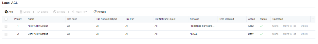
Configuration Steps
An enterprise deploys Network Secure as a gateway to enable the DNS proxy function. For security purposes, you need to disable the permission of port 53 of accessing the DNS service in the WAN zone.
- Click Add. Then, the Add Local ACL Policy dialog box appears.
Name: Enter Deny_WAN_DNS.
Source:
Network Object: Select All.
Src Zone: Select WAN.
Services:
Services: Select built-in related DNS services.
Action: Select Deny.
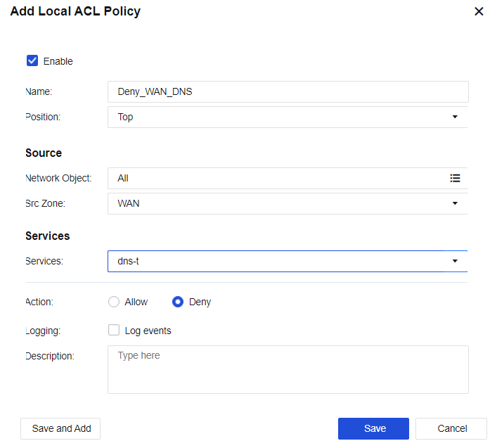
-
Click Save. Then, the configuration is complete.
-
PCs in the LAN segment can use Network Secure to perform DNS resolution. After the WAN IP address telnet test, it is verified that port 53 for Network Secure’s WAN interface DNS service is not available.
Connection Control
To set the maximum sessions for a single IP address. It includes Max Concurrent Connections Per Src IP, Max Concurrent Connections Per Dst IP, and Max Concurrent Connections.
Max Concurrent Connections Per Src IP: When LAN users are downloading applications such as P2P and when their PCs are infected with a virus, many connections will be sent in a short period, thus affecting the performance of the network device. In that case, you can select Max Concurrent Connections Per Src IP to set the maximum sessions of a single LAN IP address to reduce network loss.
Max Concurrent Connections Per Dst IP: Control the number of concurrent connections of destination IP addresses.
Max Concurrent Connections: Control the number of concurrent connections of bidirectional IP addresses.
Configuration Example
An enterprise administrator wants to limit the maximum number of sessions for LAN users, and the maximum number of concurrent sessions for a single user is 500.
-
Click Add and select Src IP Connection Control for configuration.
-
In the Add Max Concurrent Connections Per Src IP dialog box, enter the name, select LAN for the Src Zone parameter in the Source section, and select Internal for the Src Address parameter. For more information about how to define the network object, see Chapter 8.1 Network Objects. Enter 500 for the Max Concurrent Connections Per IP parameter. See the figure below.
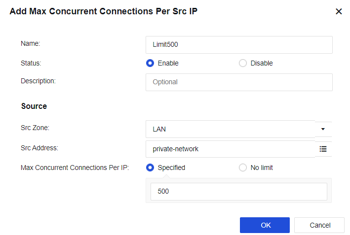
-
Click OK to validate the configuration.
-
When the number of new TCP concurrent connections on the LAN exceeds 500, new TCP connections cannot be established.
Notice:
The connections control is only valid for TCP connections.
Network Security
Network Security is one of the core functions of Network Secure. It can safely detect traffic passing through Network Secure, block malicious behaviors, and perform correlated blocks. A closed-loop mechanism is established through prediction before an event, safety protection during the event, detection and response after the event. Network Security policies mainly include web application firewall, intrusion protection, content security, tamper protection, botnet detection, DDoS protection, service model learning and supervision, and risk analysis.
Security Protection Policy
Security protection policy is a unified entrance for configuring security functions. It allows for configuring five security functions, including Passive Vulnerability Scan, Intrusion Prevention, Content Security, Web App Firewall, and Botnet Detection.
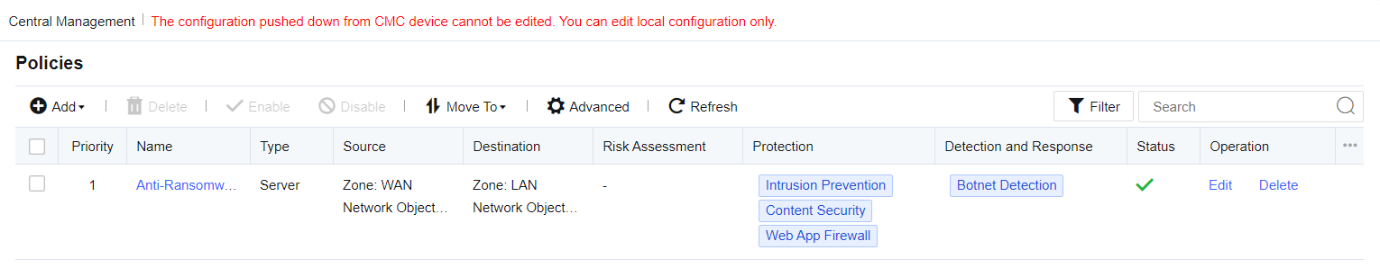
You can add, delete, enable, disable, move up, move down, move, refresh or filter security protection policies, or configure advanced settings.
It is to protect traffic direction accurately, so the correctness of traffic direction is related to whether the corresponding attack behavior can be detected.
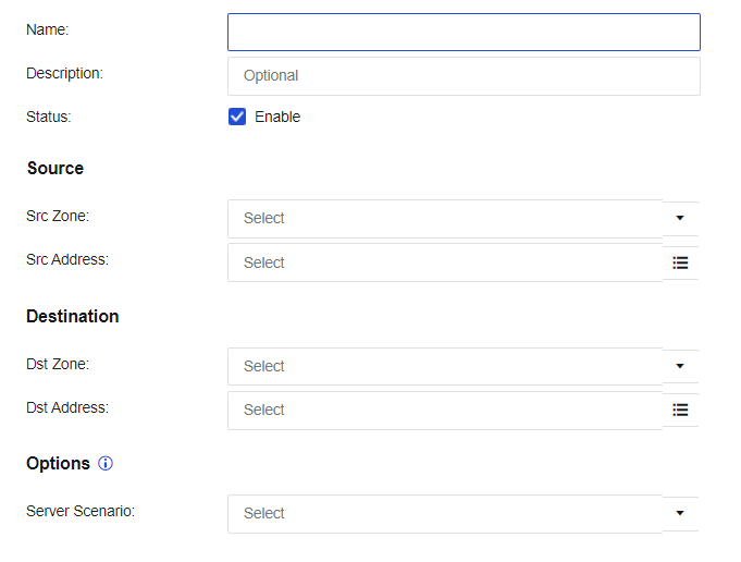
Policy for Server Scenario
Policy for server scenario mainly protects users’ services to prevent the service server from being attacked and improve network security. It mainly includes these functional modules: passive vulnerability scan, intrusion prevention, content security, web app firewall, website tamper protection, botnet detection, and correlated block.
Click Add and select Policy for Server Scenario, as shown in the following figure.
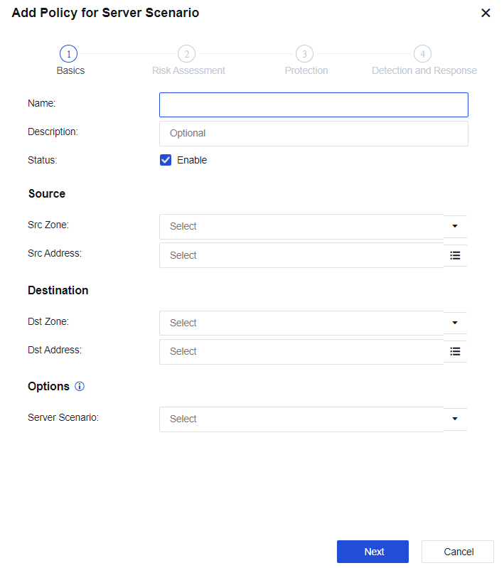
Name: Specify the name of the policy.
Description: Specify custom description.
Status: Specify whether to enable the policy.
Source
Src Zone: Select the zone where the attack data is initiated.
Src Address: Select the source IP address of the zone where the attack data is initiated.
Destination
Dst Zone: Select the destination zone where the data access direction is located.
Dst Address: Select the destination IP address of the zone where the data access direction is located.
For more information about network configuration, see Chapter 6.3.1 Security Protection Policy.
Options
Server Scenario: Determine in advance whether there will be proxy scenarios, such as SNAT or CDN, during access. Two options are available: Source is not processed via SNAT or CDN and Source is processed via SNAT or CDN. The setting is mainly for the reference of the subsequent anti-scanning policy. If you select Source is not processed via SNAT or CDN, an alert message will appear when you select Default Template II(Scanner Blocker enabled for non-proxy access) in the Risk Assessment step.
Notice:
Content Distribution Network (CDN) is an intelligent virtual network based on the existing network. It relies on the edge servers deployed in various places and enables users to obtain the required contents nearby through the functional modules such as load balancing, content distribution, and scheduling of the central platform. It will reduce network congestion and improve user access response speed and hit rate. If the edge server cannot provide this service, it will act as a proxy and use the local IP address to send a resource request to the central server.
Click Next to go to the Risk Assessment step, and check Passive Vulnerability Scan, as shown in the following figure.

Passive Vulnerability Scan: Scan passive traffic observation to detect risks such as vulnerabilities, improper configurations, and weak passwords in the service system in real time before an event occurs. Real-time analysis is conducted on the specified data in the network based on the part of built-in vulnerability rules. This function is to discover security vulnerabilities in the user’s network and present users with a report of the potential risks and solutions to the vulnerabilities. You can navigate to SOC > Business Asset Security > Passive Vulnerability Scan to view the reports.
Click Next to go to the Protection step. See the figure below.
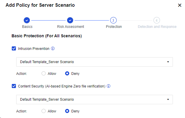
Basic Protection (For All Scenarios):
Intrusion Prevention: Select whether to enable Intrusion Prevention, for which the intrusion prevention template can be called. Identify attacks against system vulnerabilities, application vulnerabilities, and brute-force attacks of accounts.
Content Security (AI-based Engine Zero file verification): Select whether to enable Content Security, for which the content security policy template can be called. This option includes three functions: mail security, URL filtering, and file security, based on which threats in network communication content can be effectively identified and defended.
Action: Set whether to allow or deny the data packets that meet the defined rules. If you select Allow, the data packets will be tested only and not be denied. If you select Deny, the data packets will be denied or allowed according to the action defined in the rule database.
Advanced Protection (For Server Scenario):
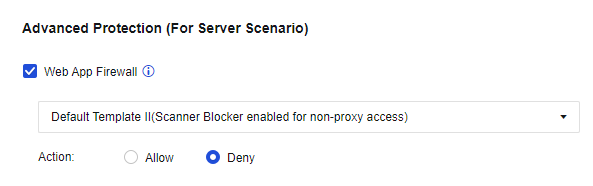
Web App Firewall: Select to enable Web App Firewall and select the related default template. It is a website protection policy specially designed for web servers, and can prevent attacks targeting web apps such as system command injections, SQL injections, and XSS attacks.
Click Next to go to the Detection and Response step. See the figure below.
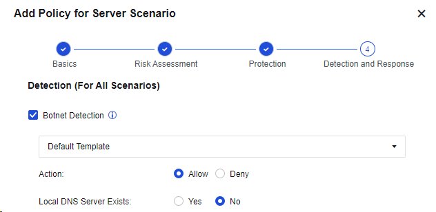
Detection (For All Scenarios):
Botnet Detection: Select to enable Botnet Detection and select the default template.
Local DNS Server Exists: If a local DNS server exists, the detected malicious domain name will be redirected. The IP address obtained by parsing the malicious domain name will be replaced by the following redirected IP address to monitor the access to the IP address, to locate the IP address of a real host infected by the botnet virus in the LAN.
Response (For All Scenarios):
Log events: Check Log events. Then, the triggered attacks will be logged in the security logs.
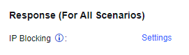
IP Blocking: Click Settings, select Enable IP blocking to enable this parameter. Then, if an attack is detected, the intrusion prevention rules, WAF rules, or content security module will block the source IP address of the attack.
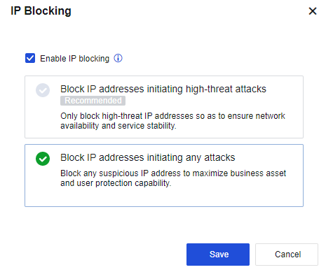
Note:
- Block IP addresses initiating high-threat attacks: It is a high-level rule specified for intrusion prevention, WAF, and DoS.
- Block IP addresses initiating any attacks: The correlated block will be triggered by the "blocking" event in intrusion prevention, WAF, and DOS.
- Triggering IPS password blasting, WAF vulnerability anti-scanning, CC attack, backdoor anti-scanning, and DDoS attack will be automatically blocked, without enabling IP blocking.
Configuration Example of Passive Vulnerability Scan, WAF, IPS, and LAN Security
An enterprise uses a web server to provide services to the internet and often suffers from malicious attacks from the internet, resulting in service exceptions. Therefore, for service continuity, you must deploy a Network Secure device to prevent internet attacks and ensure the security of services. You must carry out a risk analysis on the server’s vulnerabilities to detect the risk problems existing in the server.
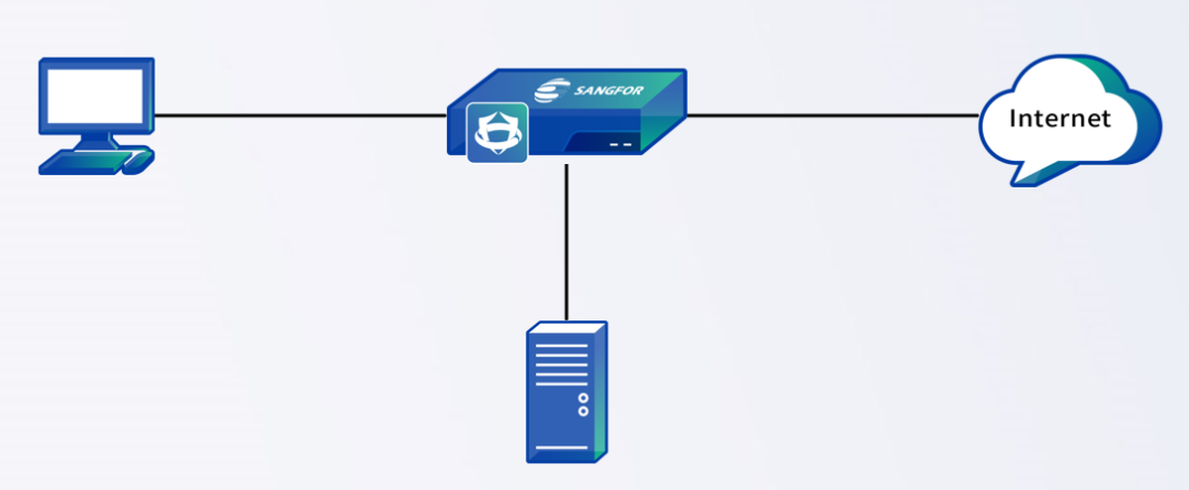
-
Optional. Create intrusion prevention, content security, web application firewall, botnet detection, and network object templates to facilitate the call of policies for server scenarios and subsequent adjustment of policies.
-
On the Policies page, click Add and select Policy for Server Scenario. In the Add Policy for Server Scenario dialog box, enter the source IP address, zone, and other information, as shown in the following figure.
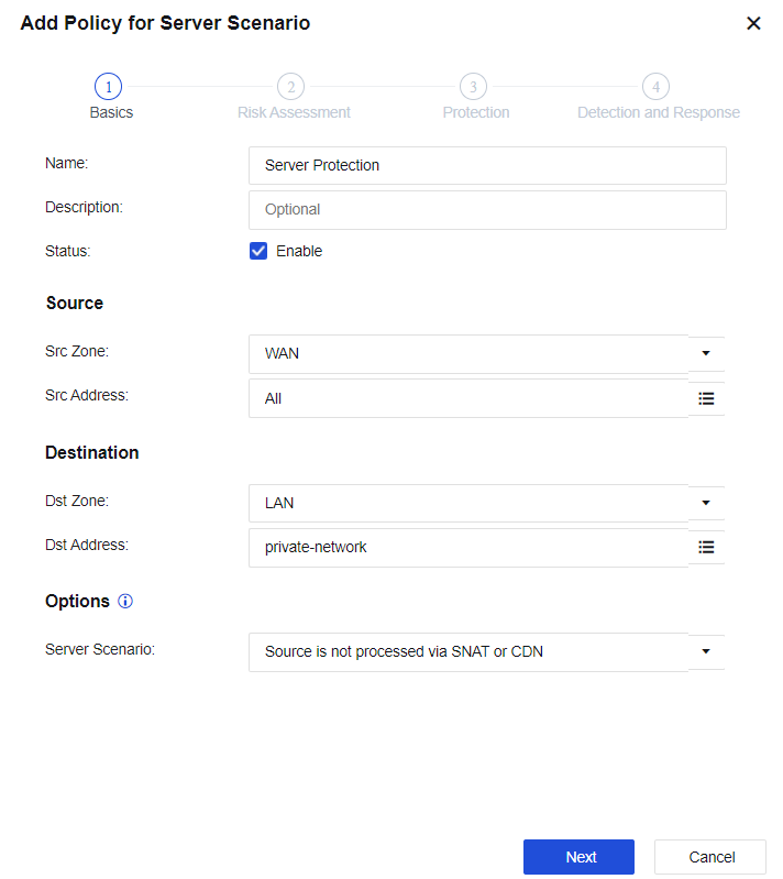
- Click Next to go to the Risk Assessment step, as shown in the following figure.
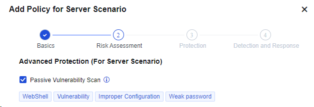
- Click Next, set the Instruction Prevention, Content Security (AI-based Engine Zero file verification), and Web App Firewall parameters, and block the attack behavior, as shown in the following figure.
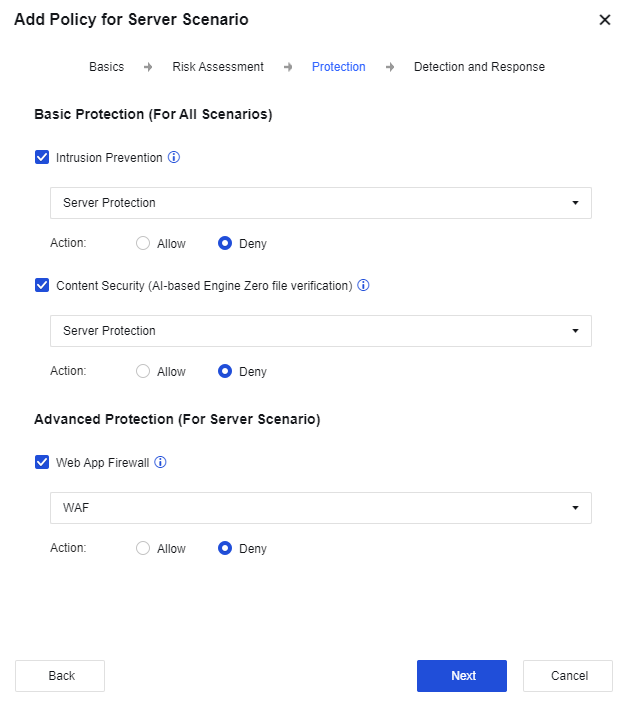
- Click Next to set the Botnet Detection and IP Blocking parameters, as shown in the following figure.
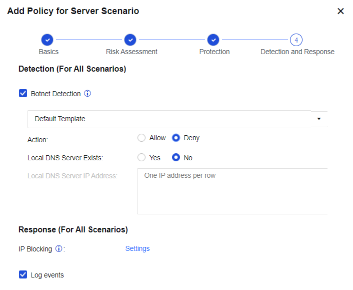
- After the configuration is complete, view the result on the Policies page.
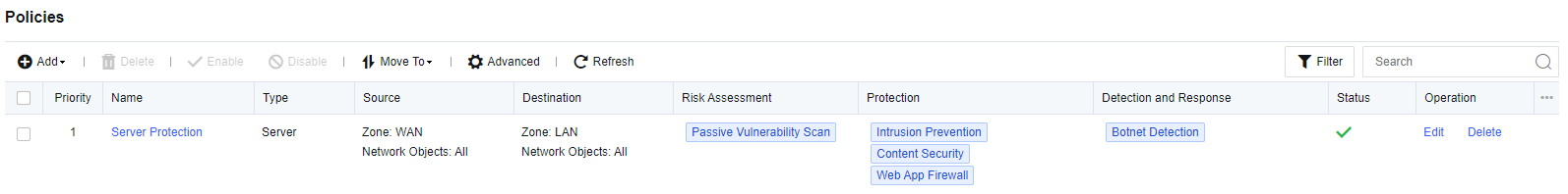
-
Use the Xhack tool to attack the LAN server via the internet.
-
View the Security Logs page for the detected malicious attacks such as WAF, IPS, and botnet, as shown in the following figure.
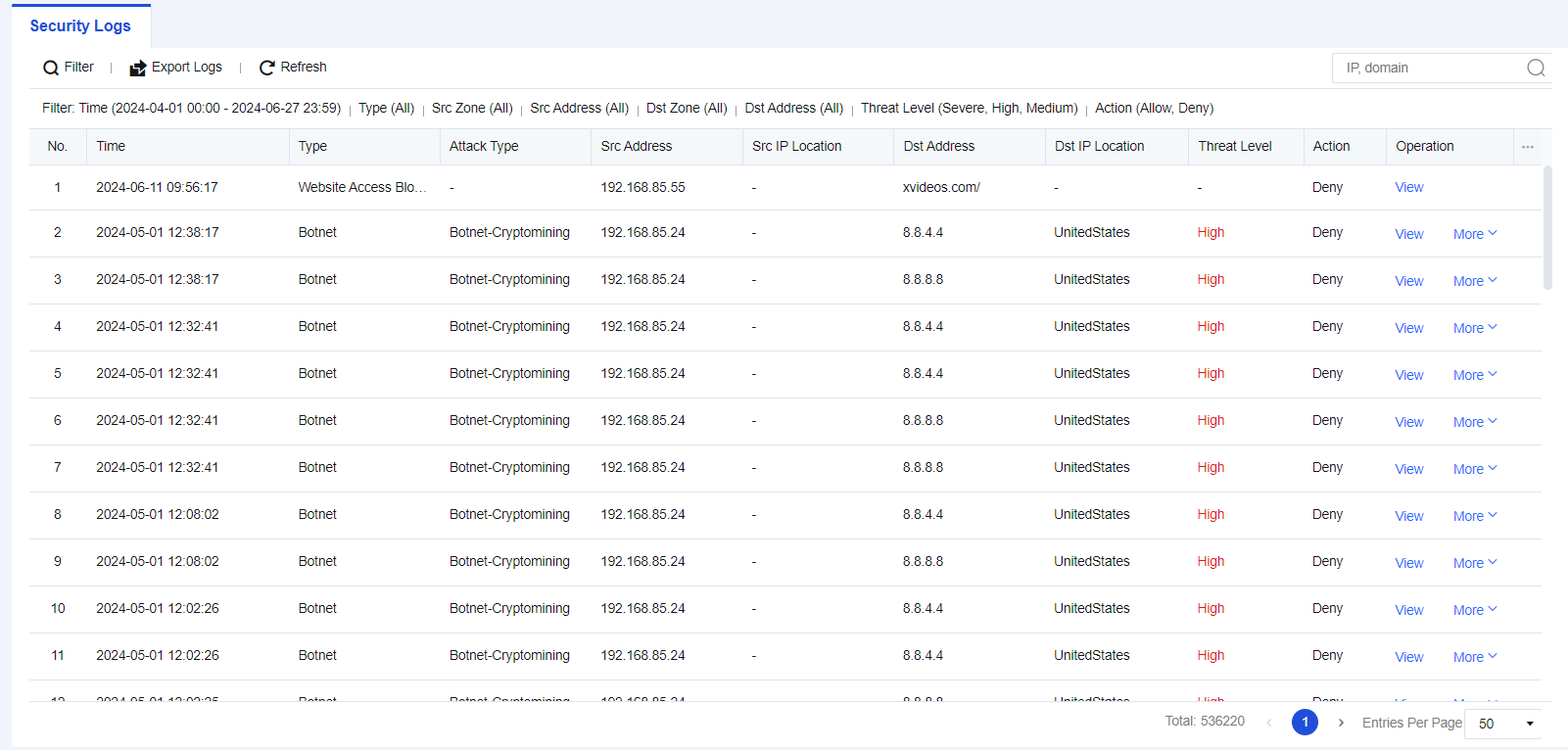
- To view the passive vulnerability scan result, navigate to SOC > Business Asset Security > Passive Vulnerability Scan, as shown in the following figure.

Policy for Internet Access Scenario
Policy for internet access scenario mainly protects the end-users of customers, to prevent endpoints from being attacked and improve the security of the LAN. This policy mainly includes functions such as intrusion prevention, content security, and botnet detections.
Configuration Case
In the office network environment of an enterprise, internal personnel may attack the internet to cause certain legal risks. Therefore, it is necessary to control the user’s internet access.

-
Optional. Create intrusion prevention, content security, botnet detection, and network object templates to facilitate the call of policies for internet access scenarios and subsequent adjustment of policies.
-
On the Policies page, click Add and select Policy for Internet Access Scenario. In the Add Policy for Internet Access Scenario dialog box, enter the source IP address, zone, and other information, as shown in the following figure.
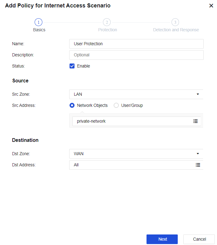
-
Click Next to go to the Protection step, as shown in the following figure.
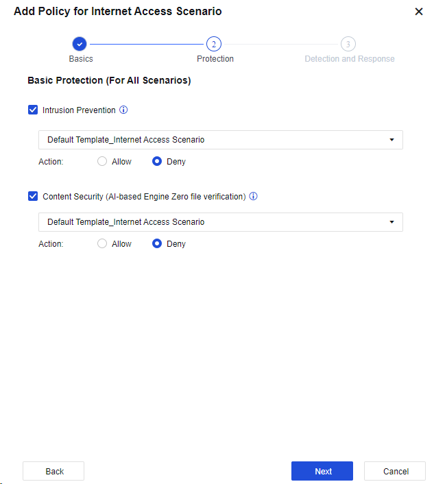
-
Click Next to go to the Detection and Response step, as shown in the following figure.
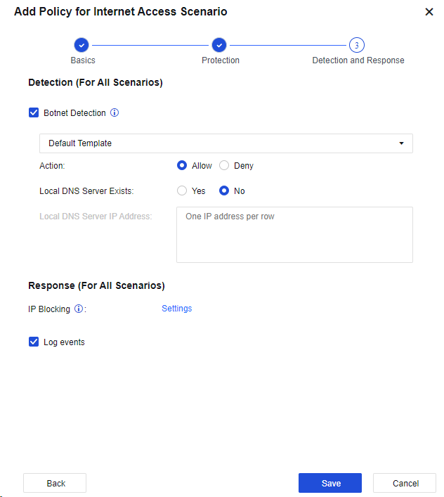
-
Click Save. Then, the configuration is complete.
-
The test results are shown in the following figure.

Advanced Settings
To add excluded items to rules that affect services or false positives. The rules with excluded items will not go through detection or be alarmed. The rules with excluded items include botnet detection, intrusion protection exclusion, passive vulnerability scan, web protection exclusion, content security, email exclusion, and file antivirus exclusion.
Click Advanced. Then, the Advanced dialog box appears, as shown in the following figure.
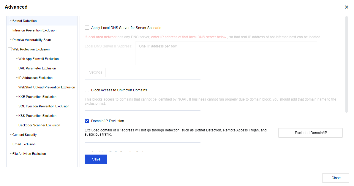
Botnet Detection
You can set the advanced functions of the botnet detection. See the figure below.
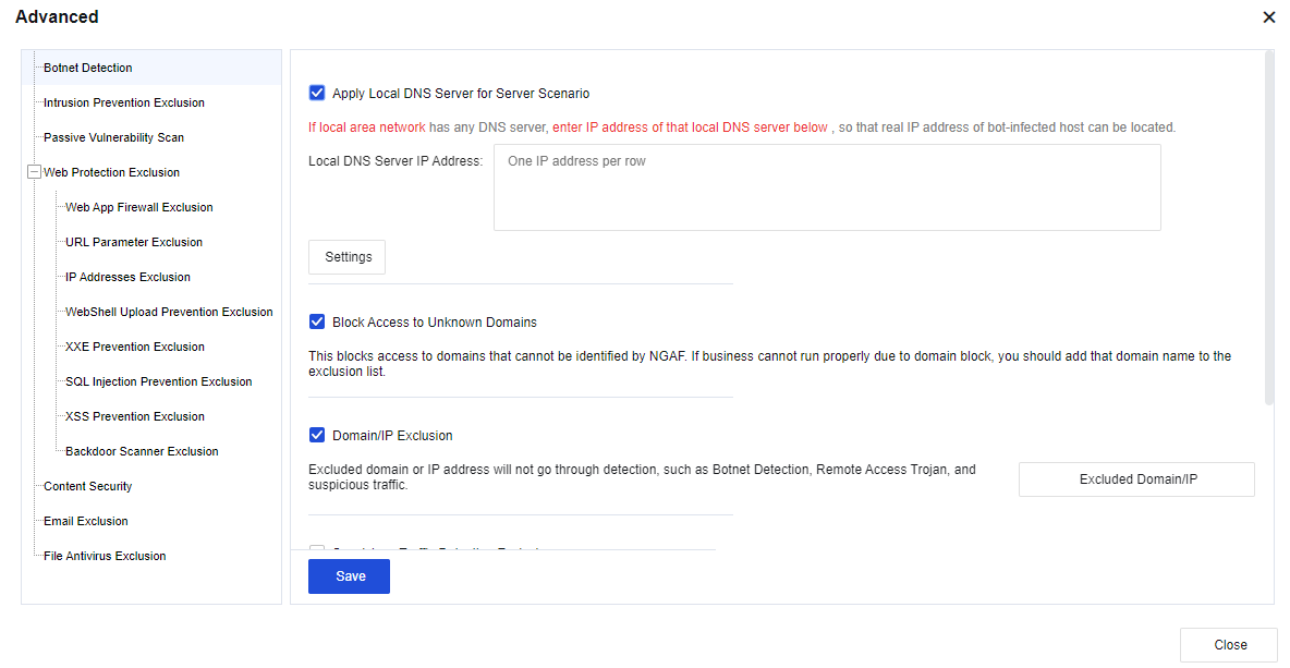
Apply Local DNS Server for Server Scenario: Select this option if a DNS server exists in the LAN. This function is used to locate the real IP address of the bot-infected host in the LAN.
Click Settings to redirect the IP address of a malicious URL to the following honeypot IP address, to monitor the access to the IP address, and locate the real IP address of the bot-infected host in the LAN.
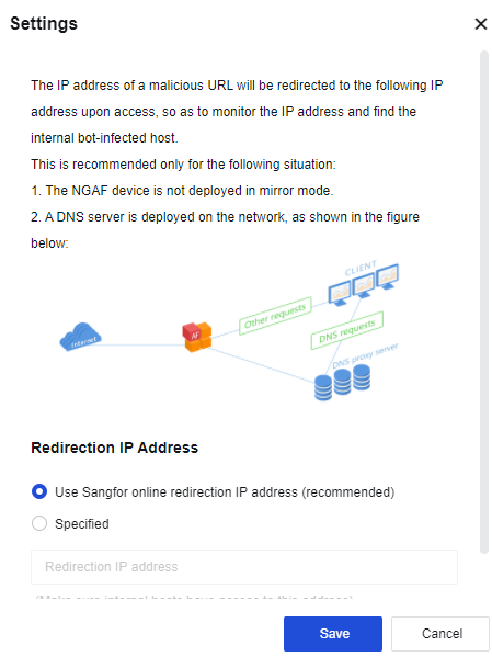
Block Access to Unknown Domains: If you select this option, access to the URLs that cannot be identified by the domain name database of the Network Secure device will be blocked. This option is often used in scenarios with high-security requirements. If the normal service cannot be accessed, it is recommended that the service’s domain name be added to the whitelist.
Domain/IP Exclusion: Excluded domain names or IP addresses will not go through detection, such as Botnet Detection, Remote Access Trojan, abnormal connections, malicious URLs, and mobile security.
Suspicious Traffic Detection Exclusion: This option is valid only for abnormal connections. If you select this operation, the excluded rules during security detection of abnormal connections for the specified destination IP addresses will not be detected.
Botnet Detection: Locate suspected botnet hosts by performing suspicious activity detection. However, all rules will only perform detection and record logs rather than blocking data traffic.
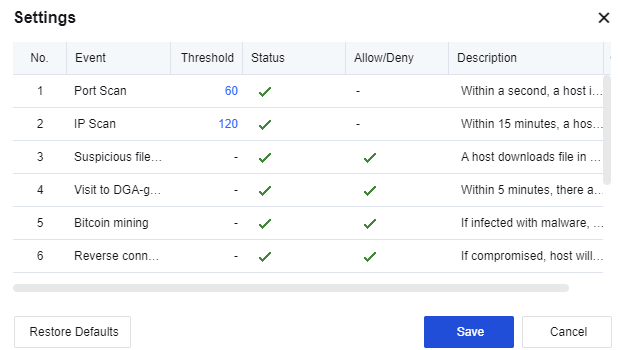
Click Save to save the advanced settings for botnet detection.
Intrusion Prevention Exclusion
To set exclusion data that does not need to be detected for intrusion prevention. See the figure below.
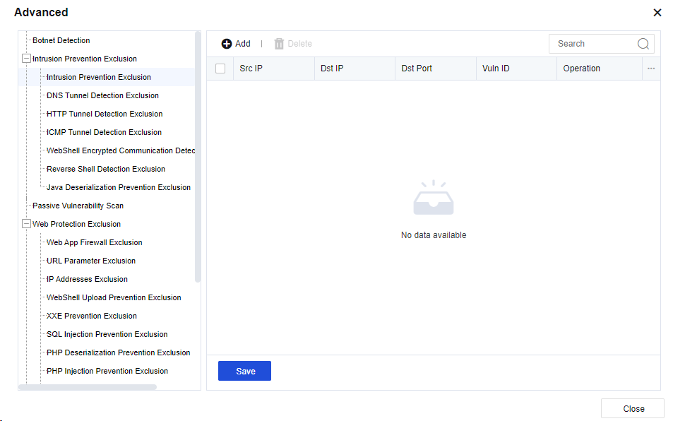
Click Add. Then, the Add Intrusion Prevention Exclusion dialog box appears. See the figure below.
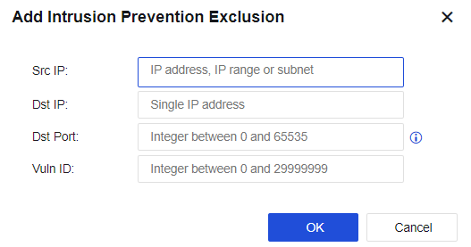
Src IP: Specify the source IP address. You can enter a single IP address, subnet, or IP address range.
Dst IP: Specify the destination IP address.
Dst Port: Specify the destination port.
Vuln ID: Specify the vulnerability ID.
Click OK. Then, the configuration is complete.
Click Save to save the settings of intrusion prevention exclusion.
Passive Vulnerability Scan
You can enable domain name, IP address, port, or URL exclusion, and set the OA service port.
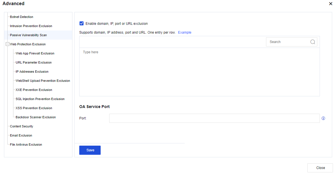
Click Save to save the advanced settings of the passive vulnerability scan.
Web Protection Exclusion
Excluded items can be added to the rules that contain false positives in web detection, including Web App Firewall Exclusion, URL Parameter Exclusion, IP Addresses Exclusion, WebShell Upload Prevention Exclusion, XXE Prevention Exclusion, SQL Injection Prevention Exclusion, XSS Prevention Exclusion, Backdoor Scanner Exclusion, etc., to reduce the occurrence of false positives, as shown in the following figure.

Web App Firewall Exclusion: Exclude the false positive rules detected by the web, thereby reducing the impact on services. Click Add. Then, the Add Web App Firewall Exclusion dialog box appears. See the figure below.
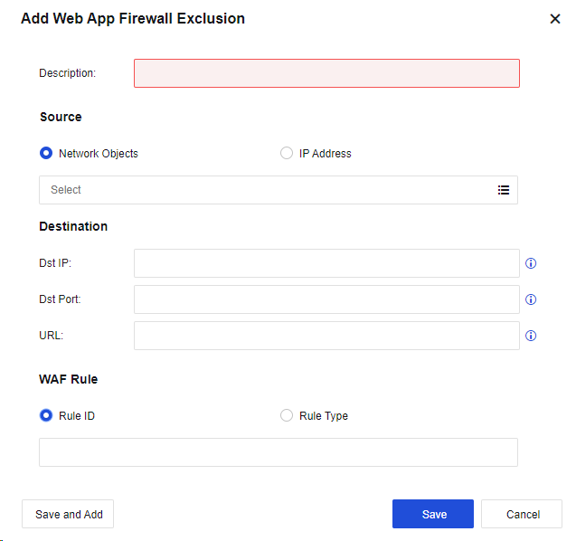
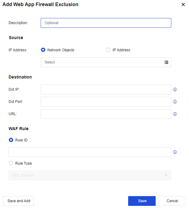
Description: Specify custom description.
Source: Specify the source IP address. You can select Network Objects or IP Address.
Dst IP: Specify the destination IP address.
Dst Port: Specify the destination port.
URL: Specify the URLs to be excluded.
Rule ID: Specify the rule ID.
Rule Type: Specify the rule type. You can add an exclusion for a specific type of rule.
Click Save. Then, the configuration is complete.
Click Save to save the settings of the web app firewall exclusion.
URL Parameter Exclusion: Add the URL parameters to be excluded. See the figure below.
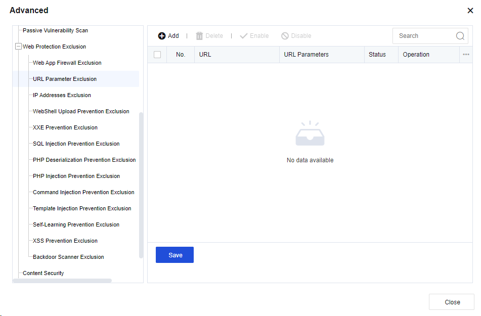
Click Add. Then, the AddURL Parameter dialog box appears. See the figure below.
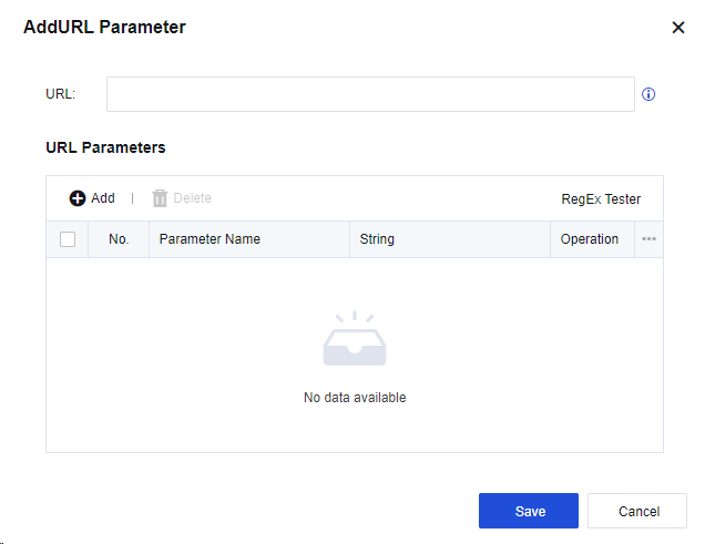
URL: Specify the URL.
URL Parameters: Specify the parameter information.
Click Save. Then, the configuration is complete.
Click Save to save the settings of the URL parameter exclusion.
IP Addresses Exclusion: Exclude IP addresses. See the figure below.
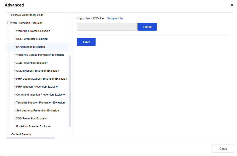
Click Sample File to download the file template. Enter the IP addresses to be excluded in the required format and import the file.
Click Save to save the settings of the IP addresses exclusion.
WebShell Upload Prevention Exclusion: If WebShell upload detected by the smart web engine has a false positive, add WebShell upload prevention into the whitelist to reduce the impact caused by the false positive. See the figure below.
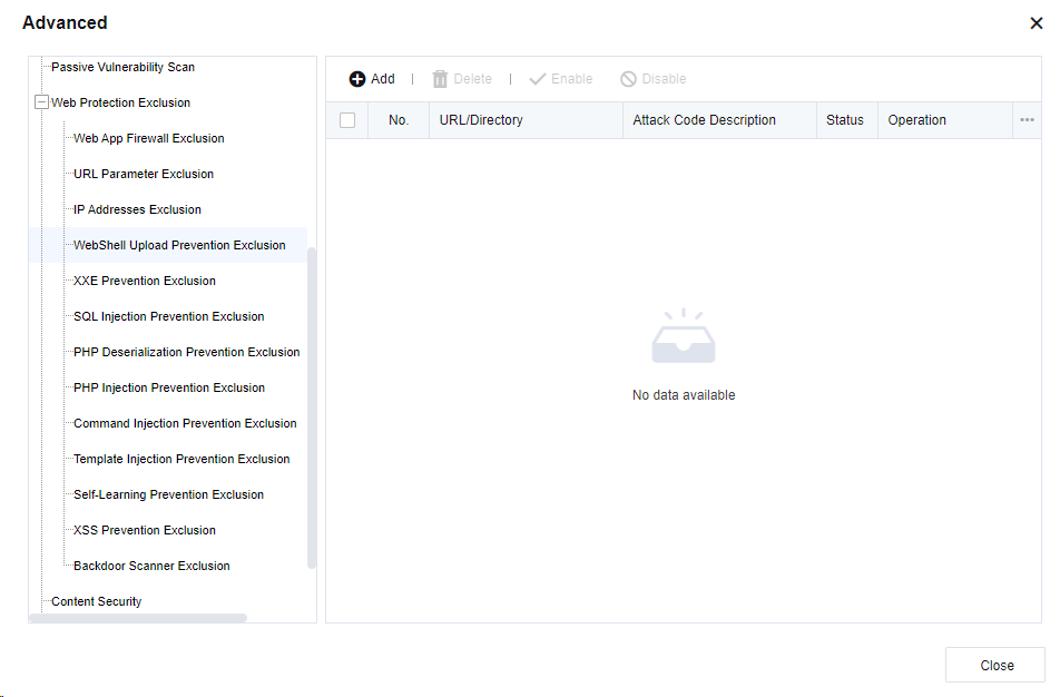
Click Add to go to the Security Logs tab and add exclusion after the security log, which can be added to the whitelist.
XXE Prevention Exclusion: If the XXE prevention detected by the smart web engine has a false positive, add the XXE prevention into the corresponding whitelist, as shown in the following figure.
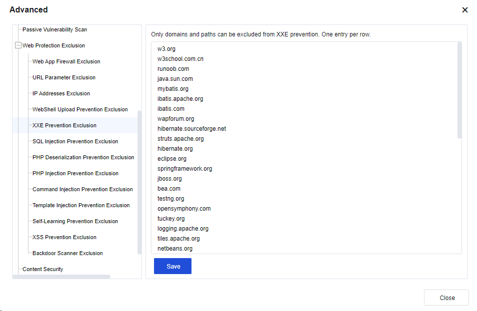
Enter the corresponding domain name and click Save. Then, the configuration takes effect.
SQL Injection Prevention Exclusion: When the SQL semantics detected by the smart web engine has a false positive, add the SQL injection prevention into the whitelist to reduce the impact caused by the false positive. See the figure below.
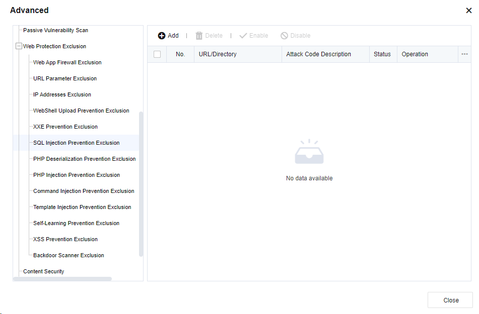
Click Add to go to the Security Logs tab and add exclusion after the security log, which can be added to the whitelist.
XSS Prevention Exclusion: If the XSS semantics detected by the smart web engine has a false positive, the XSS prevention can be added to the whitelist to reduce the impact caused by the false positive. See the figure below.
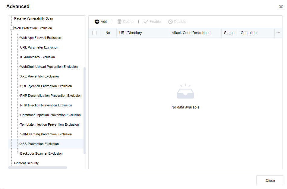
Click Add to go to the Security Logs tab, and add exclusion after the security log, which can be added to the whitelist.
Backdoor Scanner Exclusion: If the backdoor scanning detected by the smart web engine has a false positive, the backdoor scanning can be added to the whitelist to reduce the impact caused by the false positive. See the figure below.
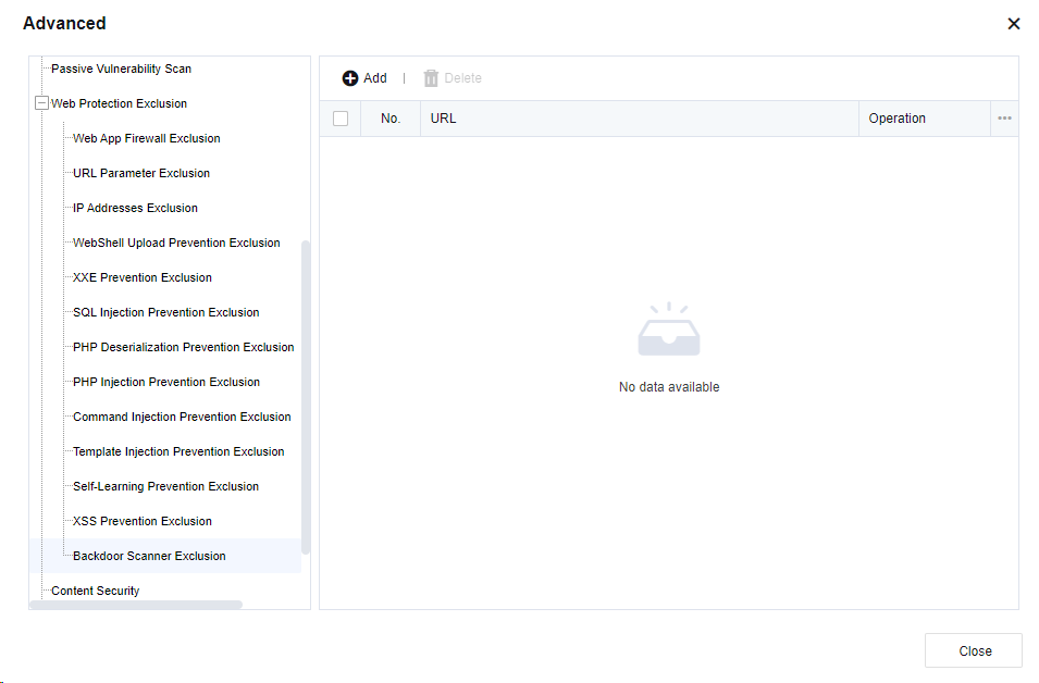
Click Add to go to the Security Logs tab and add an exclusion after the security log, which can be added to the whitelist.
Content Security
Content security mainly restricts the detection content of virus files, such as file size and compression degree, which can be adjusted accordingly. See the figure below.
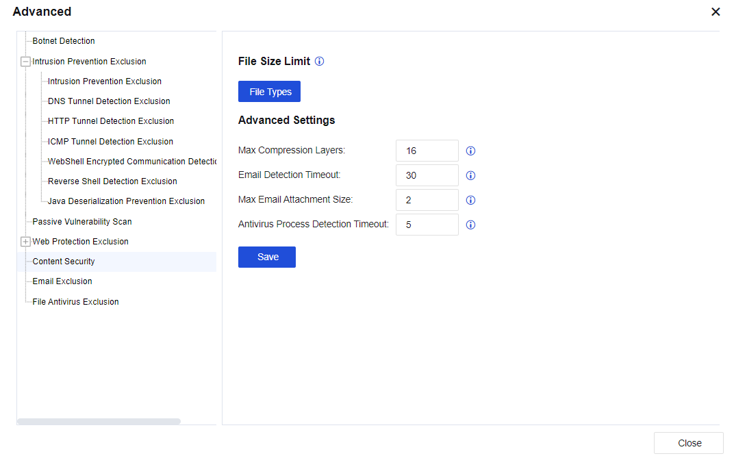
File Size Limit: Limit the size of the antivirus file. By default, the value is 10 MB. The maximum value is 20 MB. See the figure below.
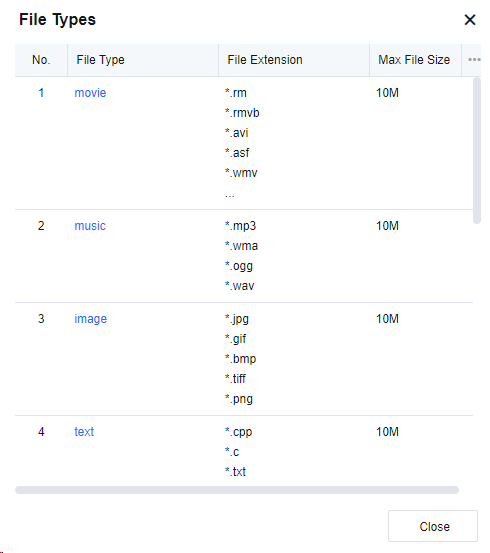
Click the name of the file type in the File Type column and change the file size, as shown in the following figure.
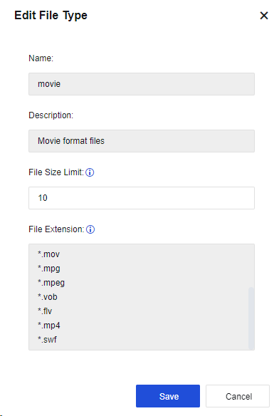
Max Compression Layers: Set the file’s layers to be decompressed to detect viruses in the decompressed file. The default value of the Max Compression Layers parameter is 4, and the maximum value is 16.
Max Layers parameter is 4, and the maximum value is 16.
Email Detection Timeout: Specify the email protection detection timeout, if exceed the timeout period, it will not continue to detect.
Max Email Attachment Size: Set the maximum email attachment size that will be sent to Engine Zero for file verification.
Antivirus Process Detection Timeout: Set the timeout period for waiting for Engine Zero results. After the timeout, the result will not be continued.
Email Exclusion
This can be set to exclude source IP addresses, destination IP addresses, recipient addresses, and sender addresses. For addresses added to the list below, all email security functions will be invalid. See the figure below.
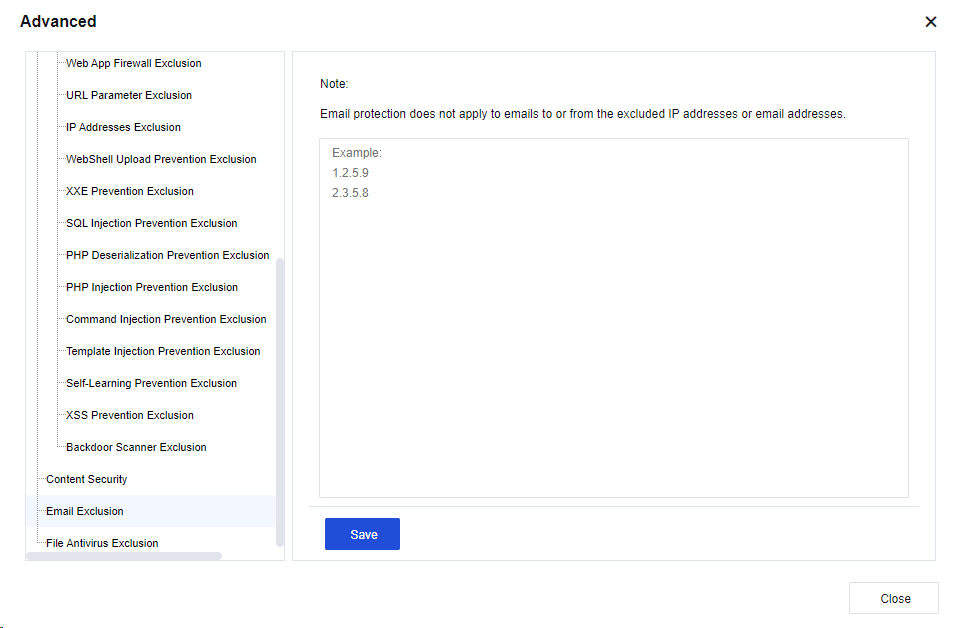
Click Save to save the settings of email exclusion.
File Antivirus Exclusion
The specified file or URL is not subject to virus scanning and killing, as shown in the following figure.
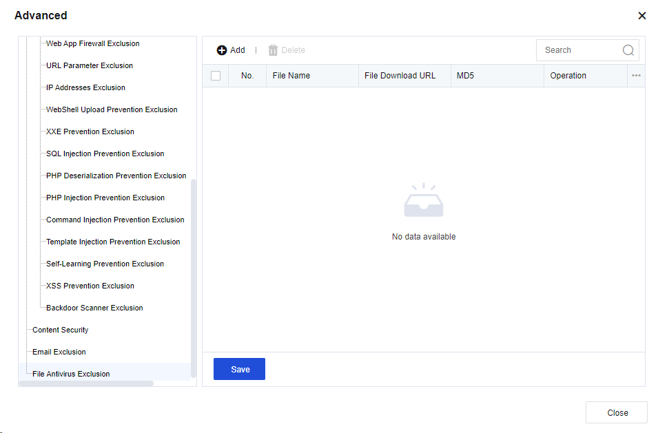
Click Add. Then, the Add File Antivirus Exclusion dialog box appears. See the figure below.
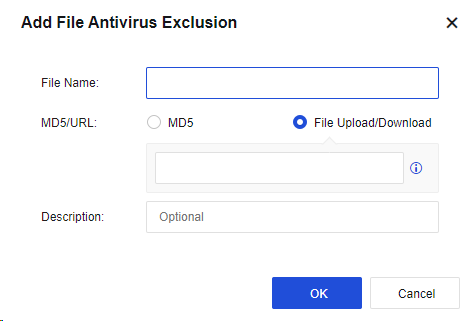
File Name: Specify the file name of the object to be excluded.
MD5/URL: Specify the MD5 value of the object or a URL to be excluded. You can select MD5 or File Upload/Download.
Description: Specify the description of the object.
Click OK. Then, the configuration is complete.
Click Save to save the settings of file antivirus exclusion.
Anti DoS/DDoS
The DoS/DDoS attack (denial-of-service/distributed denial-of-service attack) consumes server resources and forces services to stop responding. The DoS/DDoS attack causes a server response block by forging request data at a volume that exceeds the server’s handling capability, so normal user requests cannot get a response. The anti-DoS attack function of the Network Secure device can be divided into two parts according to the attack direction: Inbound attack protection and Outbound attack protection. This prevents DoS attacks from WAN to LAN and protects devices on the LAN from viruses or DoS attacks launched by using attack tools. You can add, delete, enable, disable, move up, move down, move, or refresh DDoS protection policies.
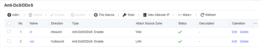
Inbound Attack Protection Policy
The WAN initiates DoS attacks on the LAN, which consume server resources and seriously affect business continuity. Therefore, DoS attacks on the WAN have become mainstream DoS attack means. By default, the inbound attack protection policy is disabled. To enable it, navigate to System > General Settings > Network, as shown in the following figure.
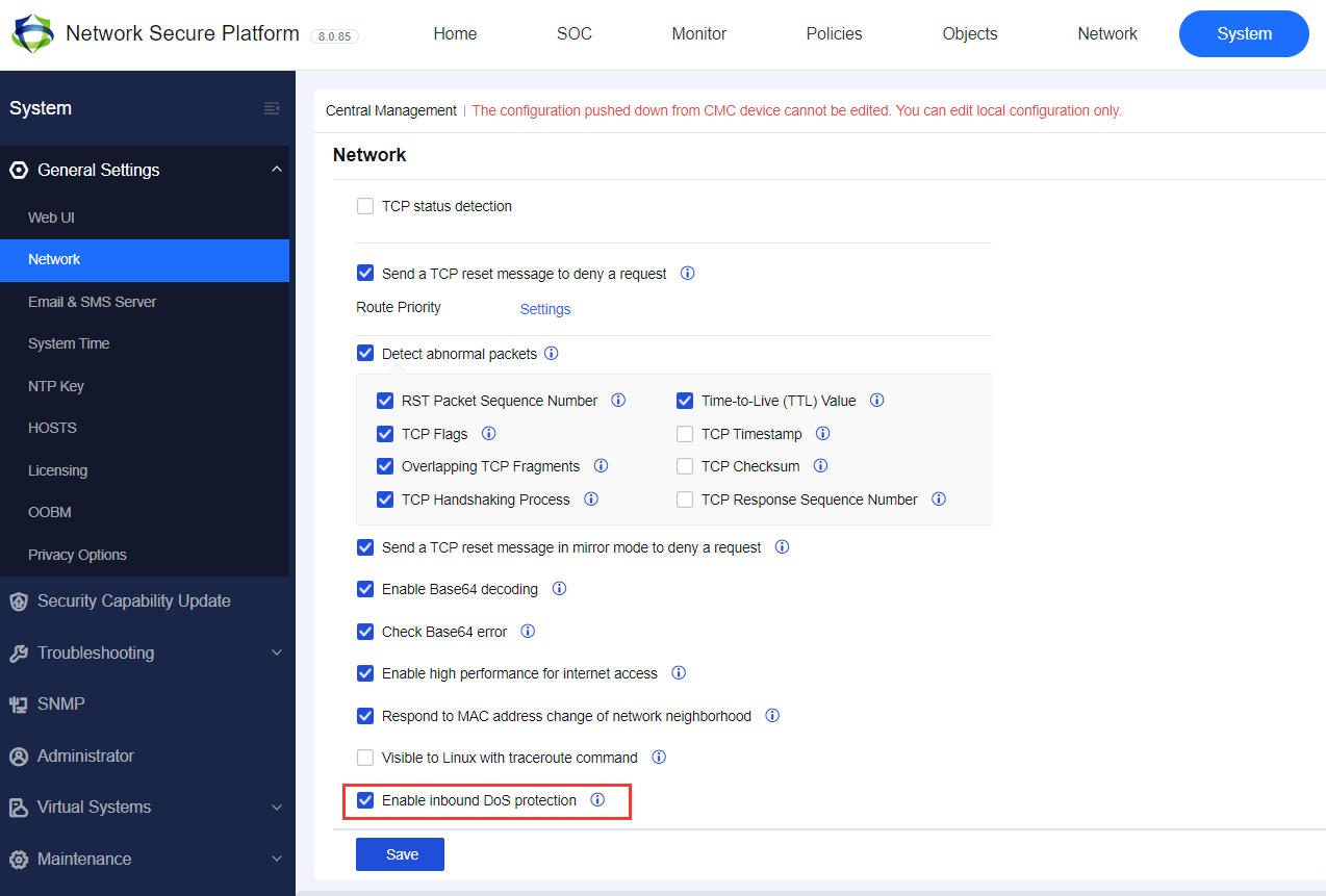
On the Anti-DoS/DDoS page, click Add, and select Inbound Attack Protection. Then, the Add Inbound Attack Protection Policy dialog box appears, as shown in the following figure.

Name: Enter the name of the protection policy.
Description: Enter the description of the policy.
Source
WAN Zone: Select the source zone to be protected. The source zone of WAN protection is usually an external one.
ARP flood protection: Select this option to enable protection against ARP flood attacks. You can set the Per-Src-Zone Packets Threshold (packets/sec) parameter. If the interface of the zone receives more ARP packets per second than the threshold, it indicates that an attack has occurred. If you select Block for the Action parameter in the lower part of the page, the ARP packets exceeding the threshold will be dropped after an attack is detected.
Protection Features
Scan Type: Select IP Scan and Port Scan. See the figure below.
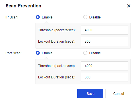
IP Scan: Enable this function and set the Threshold (packets/sec) parameter. If IP address scanning packets received from the source zone per second exceed the threshold, it indicates that an attack has occurred. If you select Block for the Action parameter in the lower part of the page, all data of the source IP address will be blocked within 5 minutes after an attack is detected. The lockout will end in 5 minutes. The number of scanning packets of the IP address will then be calculated once again.
Port Scan: Enable this function and set the Threshold (packets/sec) parameter. If port scanning packets received from the source zone per second exceed the threshold, it indicates that an attack has occurred. If you select Block for the Action parameter in the lower part of the page, all data of the source IP address will be blocked within 5 minutes after an attack is detected. The lockout will end in 5 minutes. The number of port scanning packets of the IP address will then be calculated once again.
Network Object: Indicate the object to be protected, generally the destination IP address.
Attack Type: Click Selected: DNS flood protection,ICMP flood protection,SYN flood protection,UDP flood protection to set the respective thresholds for SYN Flood, UDP Flood, DNS Flood, and ICMP Flood, as shown in the following figure.
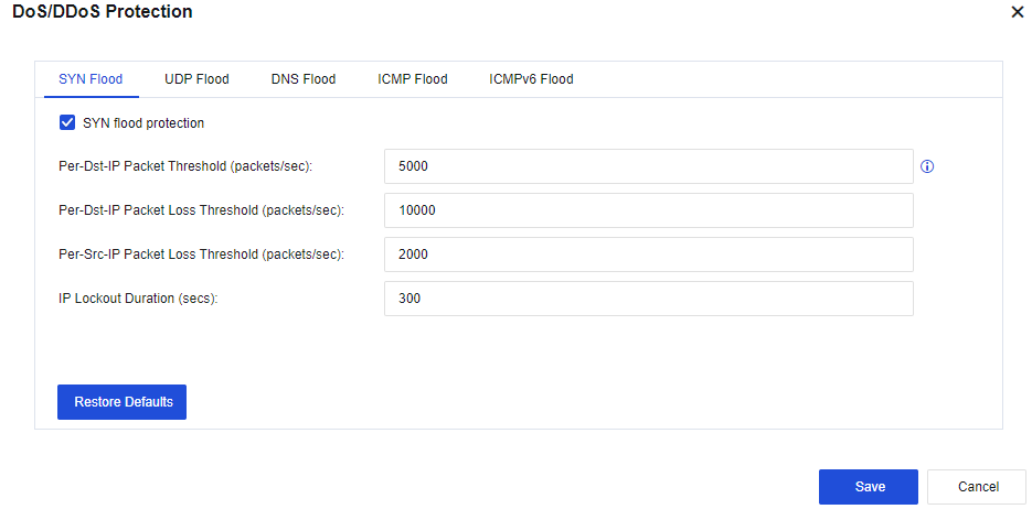
SYN Flood:
Per-Dst-IP Packet Threshold (packets/sec): Record the packets per second (PPS) of the SYN packets reaching each destination IP address. If the PPS exceeds the preset value, the NSF SYN proxy mechanism will be triggered to release the server’s load. It is recommended to set this threshold lower than the packet loss threshold (half of the packet loss threshold is the best). Valid values: 1 to 100,000,000.
Per-Dst-IP Packet Loss Threshold (packets/sec): Record the PPS of the SYN packets reaching each destination IP address. If the PPS exceeds the preset value, the protection mechanism will be triggered. Valid values: 1 to 100,000,000.
Per-Src-IP Packet Loss Threshold (packets/sec): Record the PPS of the SYN packets reaching each source IP address. If the PPS exceeds the preset value, the protection mechanism will be triggered. Valid values: 1 to 100,000,000.
IP Lockout Duration (secs): Indicate the time after which lockout automatically starts when an event is triggered. Valid values: 0 to 1,800s. You can view attack IP addresses and lockout duration in the attacker list.
UDP Flood:
Per-Dst-IP Packet Loss Threshold (packets/sec): Record the PPS of the UDP packets reaching each destination IP address. If the PPS exceeds the preset value, the protection mechanism will be triggered. Valid values: 0 to 100,000,000.
Per-Src-IP Packet Loss Threshold (packets/sec): Record the PPS of the UDP packets reaching each source IP address. If the PPS exceeds the preset value, the protection mechanism will be triggered. Valid values: 0 to 100,000,000.
IP Lockout Duration (secs): Indicate the time after which lockout automatically starts when the PPS per destination IP address and the PPS per source IP address exceed the preset value. Valid values: 0 to 1,800s. You can view attack IP addresses and lockout duration in the attacker list.
DNS Flood:
Per-Dst-IP Packet Loss Threshold (packets/sec): Record the PPS of the DNS packets reaching each destination IP address. If the PPS exceeds the preset value, the protection mechanism will be triggered. Valid values: 0 to 100,000,000.
Per-Src-IP Packet Loss Threshold (packets/sec): Record the PPS of the DNS packets reaching each source IP address. If the PPS exceeds the preset value, the protection mechanism will be triggered. Valid values: 0 to 100,000,000.
IP Lockout Duration (secs): Indicate the time after which lockout automatically starts when the PPS per destination IP address and the PPS per source IP address exceed the preset value. Valid values: 0 to 1,800s. You can view attack IP addresses and lockout duration in the attacker list.
ICMP Flood:
Per-Dst-IP Packet Loss Threshold (packets/sec): Record the PPS of the ICMP packets reaching each destination IP address. If the PPS exceeds the preset value, the protection mechanism will be triggered. Valid values: 0 to 100,000,000.
Per-Src-IP Packet Loss Threshold (packets/sec): Record the PPS of the ICMP packets reaching each source IP address. If the PPS exceeds the preset value, the protection mechanism will be triggered. Valid values: 0 to 100,000,000.
IP Lockout Duration (secs): Indicate the time after which lockout automatically starts when the PPS per destination IP address and the PPS per source IP address exceed the preset value. Valid values: 0 to 1,800s. You can view attack IP addresses and lockout duration in the attacker list.
Action: Select Log events and Block.
Click Advanced. Then, you can select options to enable the protection on the Packet-Based Attack, Bad IP Options, and Bad TCP Options tabs. By default, the options are not selected. See the figure below.
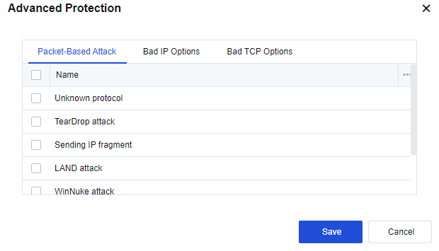
Packet-Based Attack
Unknown protocol: Select this option to enable the unknown protocol type protection. A protocol with an ID greater than 137 is considered being an unknown protocol type.
TearDrop attack: Select this option to enable TearDrop attack protection. Defense against TearDrop attacks is achieved by strict control over the fragment offset length of IP headers. If the fragment offset of an IP header does not comply with requirements, it indicates that a TearDrop attack has occurred.
Sending IP fragment: By default, the fragmented transmission of IP data blocks is not allowed. If the fragmented transmission occurs, it indicates that an attack has occurred.
Note:
Do not select this option unless it is a special case. Otherwise, the network connection may be interrupted.
LAND attack: Select this option to enable the LAND attack protection. If the device finds that the source and destination IP addresses of a packet are the same, the packet is considered a LAND attack.
WinNuke attack: Select this option to enable WinNuke attack protection. If a TCP packet header’s URG flag bit is 1 and the destination port is TCP port 139 or TCP port 445, the packet is considered as a WinNuke attack.
Smurf attack: Select this option to enable the Smurf attack protection. If the device finds that the address responded by a packet is the ICMP response request packet of the network’s broadcast address, the packet is considered a Smurf attack.
Large size ICMP packet(>1024B)#Ping of death : When an ICMP message is greater than 1024, it is considered an attack.
Bad IP Options
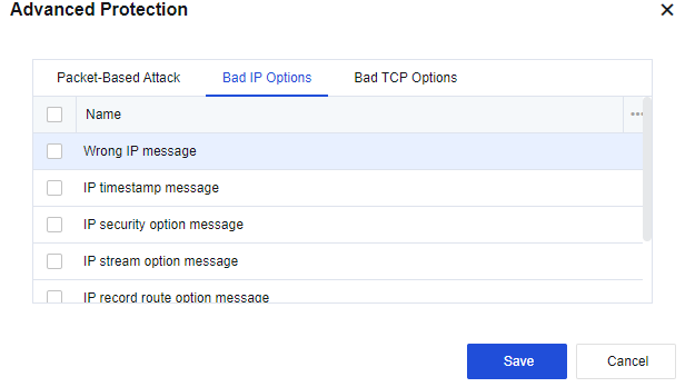
IP messages can include options such as IP timestamp message, IP security option message, IP stream option message, IP record route option message, IP loose source route option message, IP strict source route option message.
Common IP messages generally do not carry these additional options. IP messages with such options usually aim at attacking. If data messages are not allowed to carry these options, select the corresponding options for protection.
If you do not allow IP messages to carry unknown IP message options other than those listed above, select Wrong IP message.
Bad TCP Options
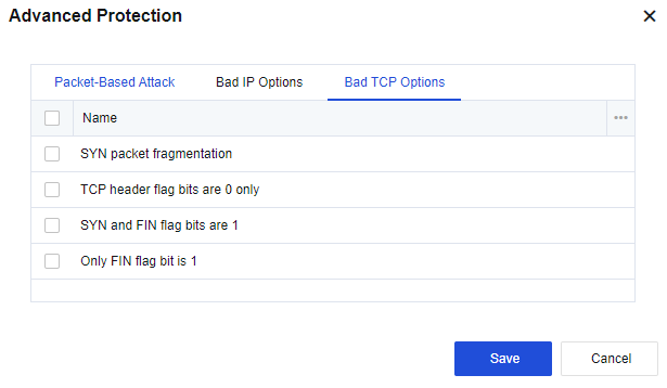
The Bad TCP Options tab includes the following options: SYN packet fragmentation, TCP header flag bits are 0 only, SYN and FIN flag bits are 1, and Only FIN flag bit is 1. Normal TCP message flags will never have these features and the target host may not be able to handle TCP messages with these features and thus become abnormal. If you select the options, the device will protect against messages with the corresponding features.
Finally, click Save to save the settings of the inbound attack protection policy.
To add more inbound attack protection policies, click Add.
To modify an existing inbound attack protection policy, click the name of the policy.
To delete a policy, select the policy and click Delete in the Operation column.
Click Enable to enable the policy.
Click Disable to disable the policy.
Click More > Move Up or Move Down to adjust the order of the policy.
Note:
For policy matching, the policy in the higher position will be matched first.
- Data packet matching is conducted from the top down and will stop after a packet matches an attack activity and is dropped. A data packet continues to check whether it matches the set attack activities until it matches one.
- If you have set scanning protection, it is good to set the information as well, such as ICMP Flood in the DoS/DDoS Protection dialog box.
- The intrusion of a hacker generally begins by scanning whether the IP addresses exist. If so, the hacker continues to scan ports. The hack will proceed to the next attack activity after the IP address and port are discovered. Some hackers may already know the IP addresses and ports and directly initiate attacks without performing scanning. Therefore, it is better to set both protection options for effective protection against attack activities.
Configuration Case
The server of an enterprise often suffers from slow service access, and some resources of the server are highly used. Packet capture reveals that this phenomenon is caused by sending a large number of SYN packets, UDP packets, etc., to some internet IP addresses and occupying many resources. Therefore, you need to configure DDoS attack protection for Network Secure deployed at the internet egress to solve this problem.
- On the Anti-DoS/DDoS page, click Add and select Inbound Attack Protection. Then, the Add Inbound Attack Protection Policy dialog box appears, as shown in the following figure.
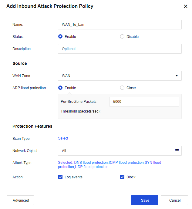
- Click Select for Scan Type to enable Scan Prevention, as shown in the following figure.

-
Select the Network Object to protect the specific IP. If no specific IP address is required, select All.
-
Click Selected: DNS flood protection,ICMP flood protection,SYN flood protection,UDP flood protection to configure DoS/DDoS Protection, as shown in the following figure.
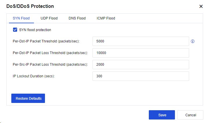
Set the SYN Flood, UDP Flood, DNS Flood, and ICMP Flood parameters according to actual requirements.
- Optional. Click Advanced to select protection options against specific attacks, as shown in the following figure.
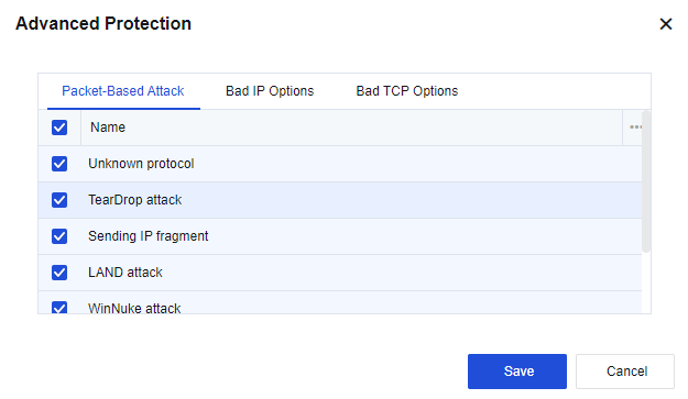
- The test results are shown in the following figures.
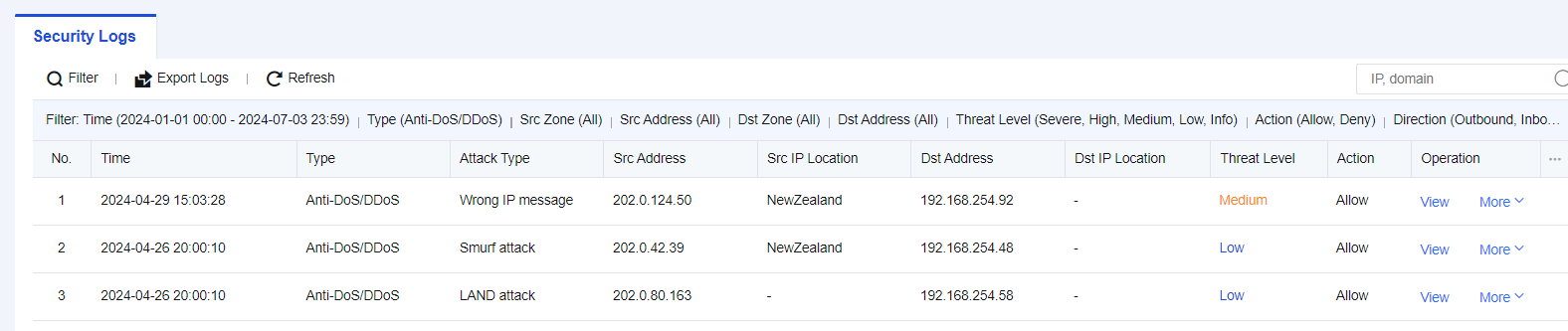
Outbound Attack Protection Policy
The outbound attack protection prevents the LAN host from becoming a zombie to attack the WAN, thus bringing certain legal risks.
Configuration Case
In the office network environment of an enterprise, it is found in the internet egress that several PCs often use excessive bandwidth, resulting in the slow speed of the LAN network. If you log in to the PC for viewing, you will find that it sends SYN and UDP messages to an IP address all the time. To prevent this recurrence, you need to add an outbound attack protection policy on the Network Secure.
- On the Anti-DoS/DDoS page, click Add and select Outbound Attack Protection. Then, the Add Outbound Attack Protection Policy dialog box appears, as shown in the following figure.
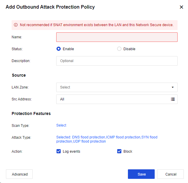
- Click Select for Scan Type to enable Scan Prevention, as shown in the following figure.

- Click Selected: DNS flood protection,ICMP flood protection,SYN flood protection,UDP flood protection to configure DoS/DDoS Protection, as shown in the following figure.
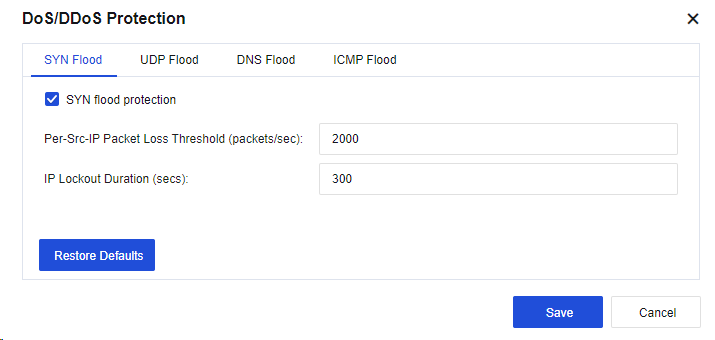
Set the SYN Flood, UDP Flood, DNS Flood, and ICMP Flood parameters according to actual requirements.
- Optional. Click Advanced to select protection options against specific attacks, as shown in the following figure.
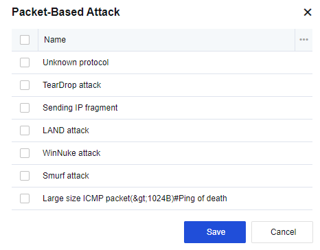
- The configuration results are shown in the following figure.
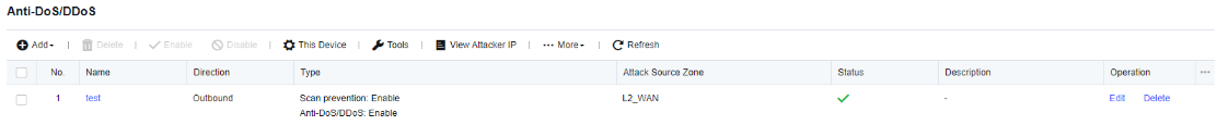
- The attack details are shown in the following figure.
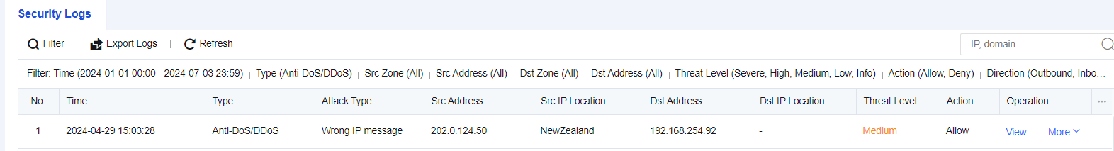
Local DoS Protection
Local DoS protection is to defend against attacks aimed at the Network Secure device itself. Click This Device Protection to set the protection type, as shown in the following figure.

Tools
Tools in Anti-DoS/DDoS are used for setting regional access control, LAN access control, and DoS exclusion, as shown in the following figure.
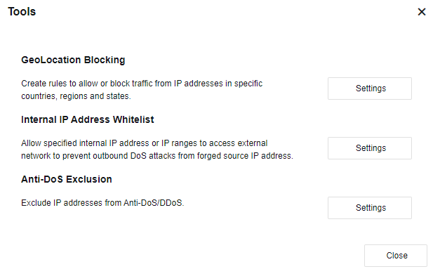
GeoLocation Blocking: Reject or allow IP traffic of the specified countries or regions. Click Settings to enter the GeoLocation Blocking page.
Internal IP Address Whitelist: Configure to only allow the outbound access of the specified IP addresses or IP ranges on the LAN. Click Settings. Then, the Internal IP Address Whitelist dialog box appears, as shown in the following figure.
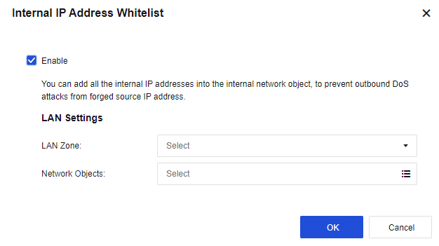
Anti-DoS Exclusion: Specify IP addresses to be excluded from the DoS/DDoS protection, as shown in the following figure.
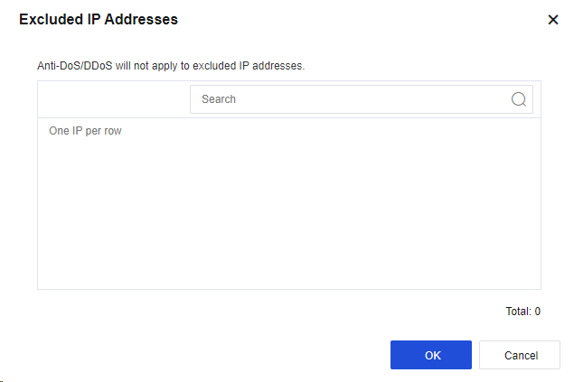
View the Attacker IP Address
Click View Attacker IP to go to the Attacker IP Addresses page, on which you can view the details such as IP addresses of active attackers or those in the last 7 days.
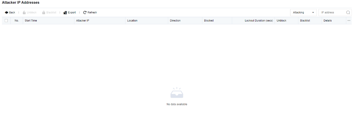
Decryption
Decryption is used for the decryption scenarios of encrypted emails and HTTPS data for LAN users who access the internet through the device and the scenario where the LAN has an encrypted server, and the Network Secure device decrypts the traffic accessing the server to protect the server. You must enable multi-functional authorization to enable this function.
Decrypt Data to Internal Server
The service released by the decryption intranet server applies to the encryption server in LAN. The Network Secure device detects the server’s traffic by decrypting the traffic accessing the server to protect the server from attacks. See the figure below.
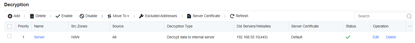
Configuration Steps
A web application server is deployed on the intranet of an enterprise to provide internal and external services. The web application server is transmitted via HTTPS protocols. To prevent the web server from being attacked, HTTPS traffic must be detected to ensure the security of the server.
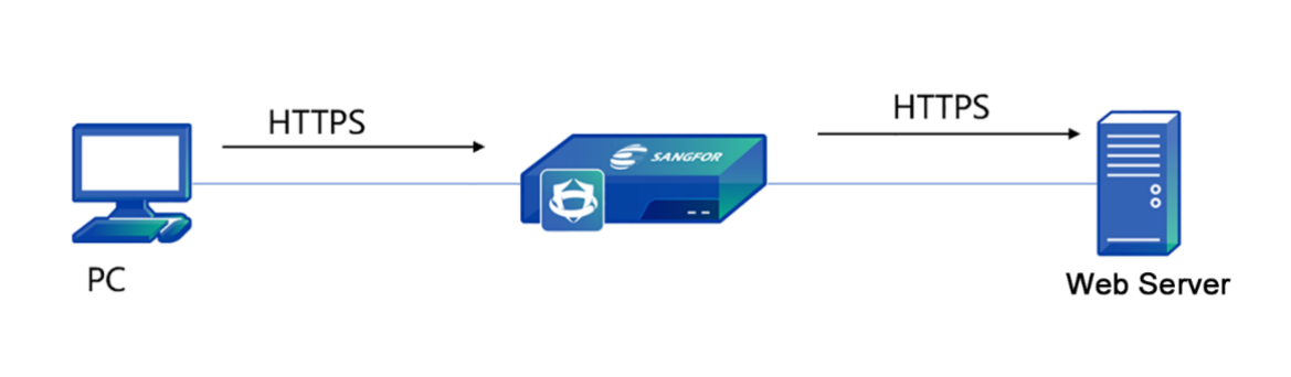
- Import the HTTPS server certificate. Click Server Certificate. Then, the Add Server Certificate dialog box appears. Click Add to create a server certificate, as shown in the following figure.
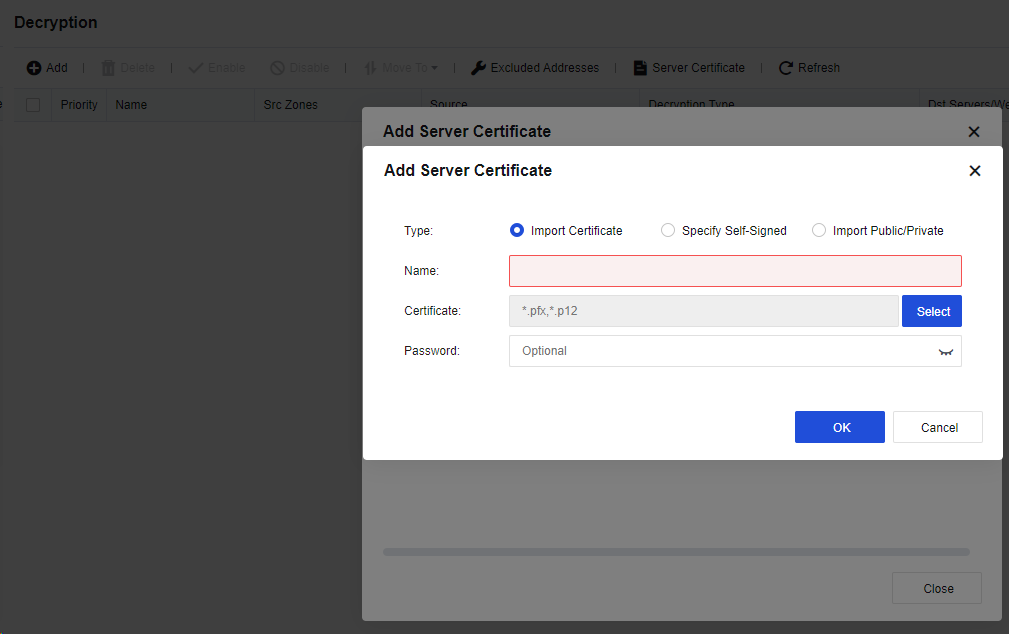
| Form of certificate | Note |
|---|---|
| Import Certificate | Import a certificate file suffixed with .pfx or .p12. The file contains the public key, private key, and password. Enter the password to decrypt the file. |
| Specify Self-Signed | Indicate the custom certificate. You need to manually specify the Name, Country, Issued To, Key Type, Key Size, and Validity Period parameters. The rest parameters are optional. A self-signed certificate can be generated after the preceding parameters are set. |
| Import Public/Private | Import a public or private key certificate. The public key certificate supports a file suffixed with .PEM or .DER, and the private key certificate supports a file suffixed with .PEM, .DER, or .PVK. Click OK after the certificate is imported. |
Table 16: Description of Form of Certificate
- Click Add to create a decryption policy and enter the corresponding information, as shown in the following figure.
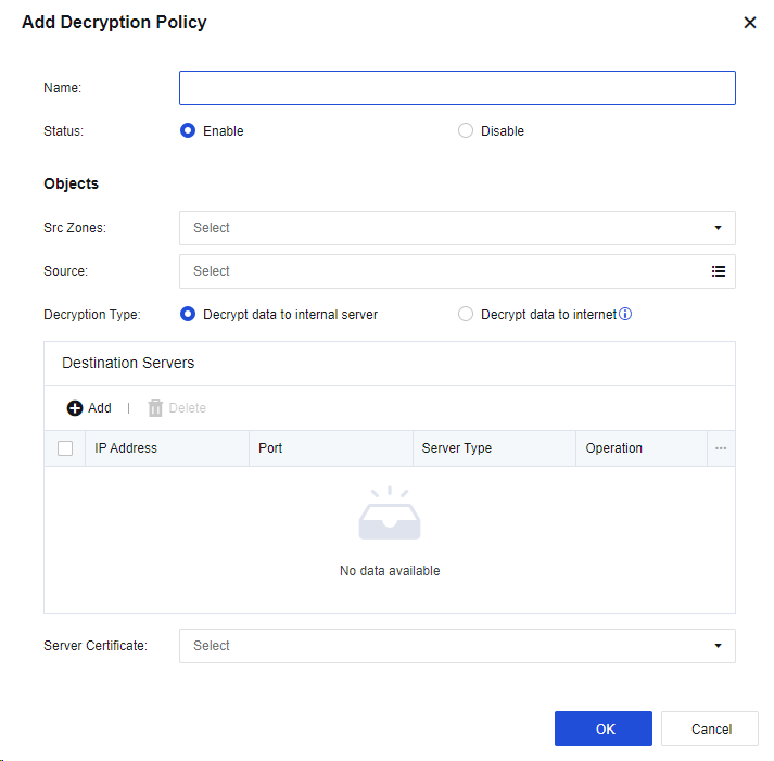
Name: Enter a policy name easy to identify.
Src Zones: Select the source zone for accessing the server.
Source: Enter the network objects that will access the server.
Decryption Type: If you select Decrypt data to internal server, the encryption server is deployed in the LAN zone of Network Secure. The Decrypt data to internet option applies to the decryption of emails and HTTPS data when LAN users access the internet.
Destination Servers: Add the IP address and port of the server to be decrypted. Web server, Mail server, FTP server, and Other servers are available.
Server Certificate: Select the certificate of the encryption server. You need to import the server certificate on the Add Server Certificate page.
- Click OK to save the settings. Then, the policy is added.
Decrypt Data to Internet
Decrypting data to the internet applies to the decryption of emails and HTTPS data when LAN users access the internet through the device. See the figure below.
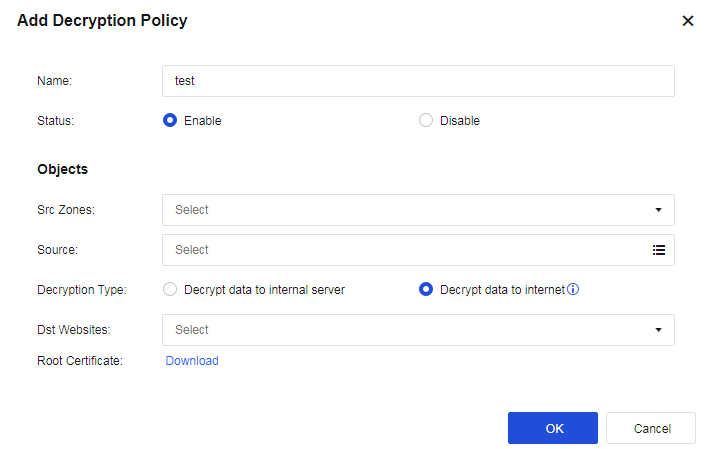
Name: Enter a policy name easy to identify.
Src Zones: Select the source zone for accessing the internet.
Source: Enter the network objects that will access the server.
Decryption Type: Select Decrypt data to internet.
Dst Websites: Select All or Selected. If you select Selected, select the site category to be decrypted from the URL category database.
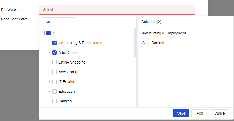
Root Certificate: When the decryption function is enabled, a certificate alert message is prompted to a user who accesses the HTTPS website. To avoid this message, select this option and set the URL from which the root certificate is downloaded.
Excluded Addresses
The excluded addresses function is to exclude the specified URLs, SNIs, and CNs from the decryption, as shown in the following figure.
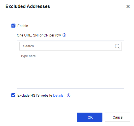
Note:
- To enable the decryption function, multi-functional authorization must be enabled.
- This function may impose some pressure on the device’s performance. Do not enable it arbitrarily.
- By default, the encrypted emails of LAN users accessing the WAN are decrypted. You only need to enable a policy for decrypting data accessing sites. The rest of the operations only need to be set in the content security policy.
- Security of encrypted emails, HTTPS antivirus, HTTPS webpage filtration, and the filtration of HTTPS uploads and downloads rely on the decryption of data accessing sites.
Bandwidth Management
Bandwidth management is to control the traffic sizes of various web applications by building bandwidth management channels.
The bandwidth management system provides the functions of bandwidth guarantee and limitation. The former ensures the access bandwidths of important applications, whereas the latter restricts the total inbound and outbound bandwidths of user groups/users and those of various applications.
The bandwidth management system also provides the traffic sub-channel function, which allows for a more refined allocation of channel traffic by building traffic sub-channel as required.
Basic Concepts:
Bandwidth Channel: Divide the bandwidth of the whole line into several parts by percentage and allocate different bandwidth resources by application type or user group. By their functions, the bandwidth channels are divided into the guaranteed channel and the limited channel.
Limited channel: Set the maximum flow rate of the channel. In the case of a busy network, the bandwidth occupied by the channel does not exceed the preset maximum bandwidth.
Guaranteed channel: Set both the maximum and minimum bandwidths of the channel. In the case of a busy network, this channel ensures that the bandwidth’s channel is not smaller than the preset minimum bandwidth.
Link: Establish a correspondence between the device’s physical network interfaces and the "Links" in bandwidth channels, specifying the interface for outbound data that can match the bandwidth management channel.
Bandwidth Channel Matching and Priority
If the status of the bandwidth management system is Enabled, data going through the device is matched to a bandwidth channel based on data details. The rules for matching involve the user group/user, IP address, application category, effective time, destination IP, and group. Data packets that meet all the rules will match the channel.
Data with the same details will only be matched to a bandwidth management policy. The matching sequence of the flow channel is matched from top to bottom, so you need to put the channel with more detailed matching conditions on the top when setting.
Channel Configuration
Guaranteed Channel
These channels guarantee the use of important applications. By setting the minimum bandwidth, they ensure that the bandwidth occupied by the specified type of data is not smaller than a particular value to ensure that important applications can use the bandwidth properly in a busy line.
Guaranteed Channel Setting
A company leases a 10Mb/s telecommunications line, and there are 1,000 Internet users on its LAN.
They need to ensure that the data of the Finance Department’s access to online banking websites and sending and receiving emails will occupy bandwidth not less than 2Mb/s when the line is busy and cannot exceed 5Mb/s.
- Go to Policies > Bandwidth Management > Bandwidth Channel, and select Enable bandwidth management system to enable bandwidth management.
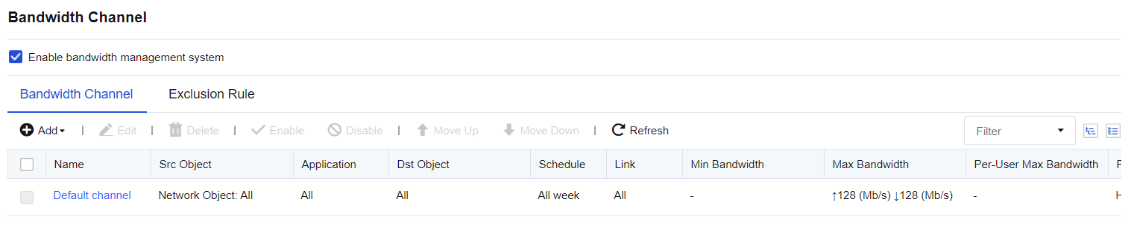
-
Go to Policies > Bandwidth Management > Link Settings to configure the link list and link rules. For more information about how to configure a virtual line, see Chapter 7.5.2 Link Settings.
-
Configure the guaranteed channel. In this example, the channel is used to ensure the bandwidth for the data of the Finance Department staff accessing the online banking websites and receive and send emails.
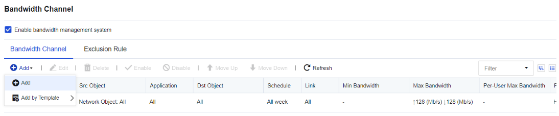
-
On the Bandwidth Channel page, click Add and select Add. Then, the Add Bandwidth Channel dialog box appears.
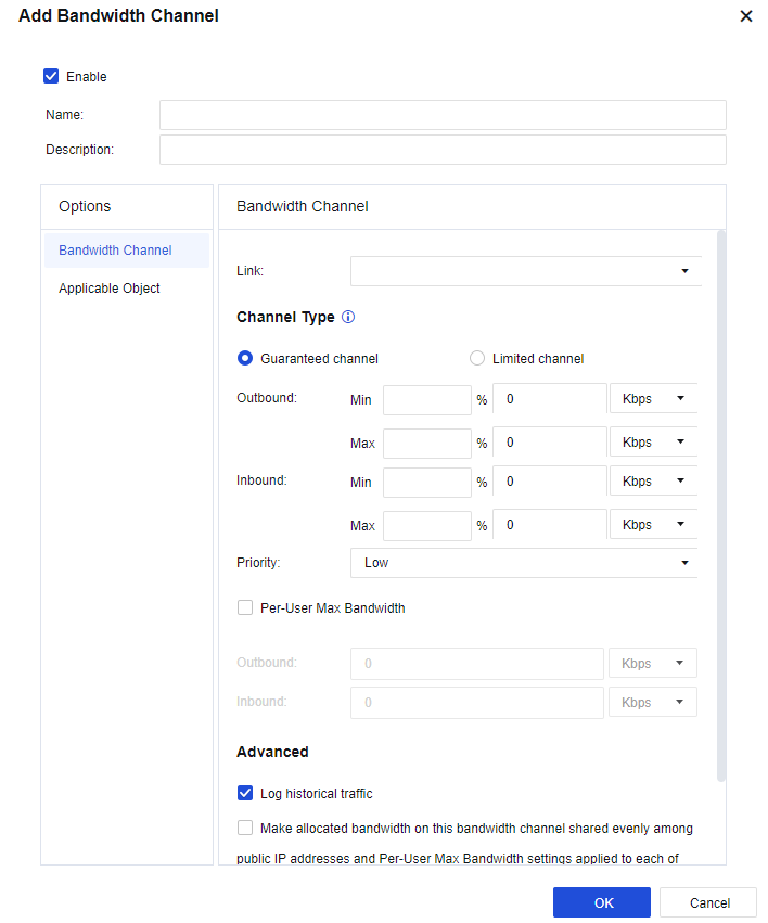
- Select Enable to enable this channel. Otherwise, the channel is disabled and the bandwidth management function does not take effect.
Name: Enter the name of the channel.
In the Options pane, select Bandwidth Channel, and set relevant attributes of the channel in the right pane.
Bandwidth Channel: Set the target line, channel type, bandwidth of the limited or guaranteed channel, and maximum bandwidth per single user, etc.
Link: Select the line applicable for the channel. In this case, the channel is matched only when the data goes through this line. The lines listed in the Link drop-down list need to be set on the Link page in advance. For more information about how to set a link, see Chapter 7.5.2 Link Settings.
Channel Type: Select the channel type and specify the bandwidth value. In this example, the bandwidth for the data of the Finance Department staff accessing the online banking websites and sending and receiving emails should be guaranteed at 2 Mb/s (Min) and 5 Mb/s (Max). Select Guaranteed channel, and set the minimum and maximum values of both outbound bandwidth and inbound bandwidth to 20% and 50% of the total bandwidth, respectively. The total bandwidth is 10 Mb/s, so the minimum bandwidth is 2 Mb/s and the maximum bandwidth is 5 Mb/s.
Priority: Include High, Medium, and Low, and indicate the priority for the channel to occupy the idle bandwidth when other channels are idle.
Per-User Max Bandwidth: Limit the bandwidth occupied by a single IP address matched to this channel. In this example, there is no need to limit the maximum bandwidth per user, so the option is not selected.
Advanced: If you select this option, each WAN IP address is considered a user in the channel, so the bandwidth is evenly allocated among channel users. Single-user maximum bandwidth attribute is made available for the WAN IP address. (This option is usually used for servers providing external services. Proceed with caution.)
Applicable Objects: Set the types of data that can be matched to the channel, i.e., the usage range of the channel. The setting range includes app category, applicable object, effective time, destination IP group, subinterface, VLAN. Data should meet all these rules to be matched to the channel.
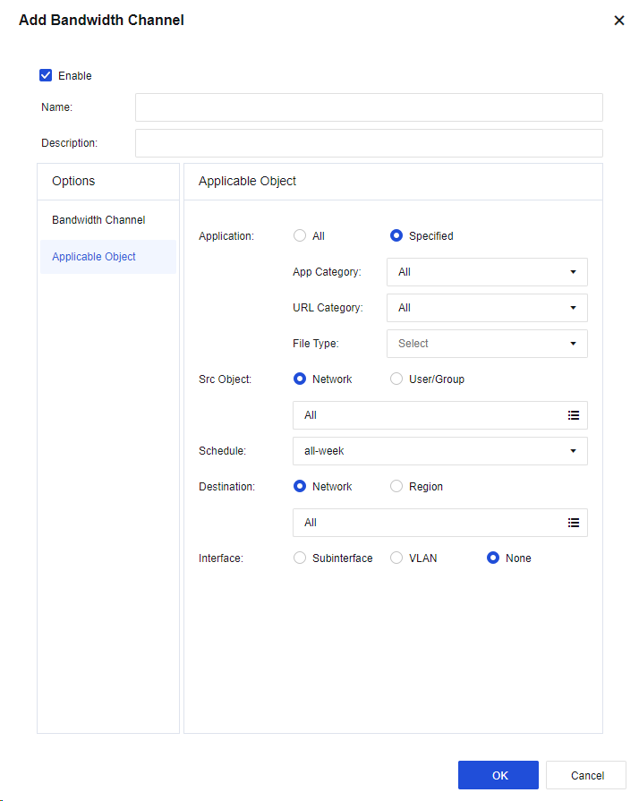
Applicable Application: Set the app category. If you select All, it is valid for all data types. If you select Specific option, there are App Category, URL Category, and File Type.
In this example, to guarantee the bandwidth for the data of receiving and sending emails and accessing online banking websites, select Mail/All and Internet Banking for the App Category.
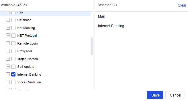
In addition, File Type is used to control the types of files downloaded via HTTP and FTP protocols. Confirm whether the range selected in Selected is correct. Click Save to complete the settings of applicable applications.
Applicable Objects: Set the network objects and user groups for which the channel is valid. The applicable object can be either IP address-based or user-based. In this example, to guarantee the bandwidth for all users in the Finance Department, select User. In the Groups section, select the required group path. In the Current Group section, select Group and User. In the Selected Groups and Users section, view the list of selected users and user groups. After you select Applicable Objects, click Save to complete the settings.
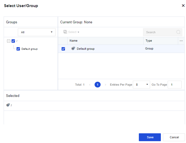
Schedule: Set the effective time of this channel.
Destination:
Network: Set the rules for the destination IP address.
Region: Set the destination IP address.
Interface:
Subinterface: Set the subinterface to which the traffic channel is applicable.
VLAN: Set the VLAN to which the traffic channel is applicable.
Choose None if no VLAN or SubInterface is available, so that the channel will be valid for the physical interface.
After you set these parameters, click OK to complete the setting for a guaranteed channel.
- After you click OK, the set channel will appear on the Bandwidth allocation, and the guaranteed channel configuration will be completed.
Note:
- The total percentage of the guaranteed bandwidth channels may exceed 100%. In that case, the minimum bandwidth of each guaranteed channel will be decreased proportionately. For example, you have set two channels, including the first with a guaranteed bandwidth of 30% and the second with a guaranteed bandwidth of 90%. So, 30/(90+30)% (i.e., 25%) is allocated to the first channel and 90/(90+30)% (i.e., 75%) to the second channel.
- Priority: When there is actual idle bandwidth, channels with higher priorities will occupy the idle bandwidth first.
Limited Channel
If you select Limited channel, you need to set the maximum channel bandwidth to control the traffic for the data matched to the limited channel and control the occupied bandwidth which shall not exceed the set maximum bandwidth.
Limited Channel Configuration
A company leases a 10 Mb/s China Telecom line and has 1,000 users on its LAN. It is found that many Marketing Department staff often use downloading tools such as Thunder and P2P to download, occupying most of the bandwidth and affecting the normal office business of other departments. We can set the bandwidth occupied by downloading to be limited to 2 Mb/s for the Marketing Department and 30 KB/s for each user via the traffic control system.
-
Navigate to Policies > Bandwidth Management > Bandwidth Channel.
-
Select Enable bandwidth management system to enable bandwidth management.
-
Navigate to Policies > Bandwidth Management > Link Settings to configure the virtual line list and virtual line rules.
-
Configure the limited channel.
In this example, the bandwidth management is performed for the P2P and downloaded data of Marketing Department personnel. The total bandwidth occupied by these applications is capped at 2 Mb/s.
On the Bandwidth Channel tab, click Add to add a limit channel. In the Add Bandwidth Channel dialog box, if you select Enable, the channel is enabled. Otherwise, the channel will be disabled and will not take effect temporarily.
Enter the name of the channel in the Name field.
In the Options pane, select Bandwidth Channel, and set relevant attributes of the channel in the right pane.

Bandwidth Channel: Set the target line, channel type, bandwidth of the limited or guaranteed channel, and maximum bandwidth per single user, etc.
Link: Select the line applicable for the channel. In this case, the channel is matched only when the data goes through this line.
Channel Type: Select the channel type and specify the bandwidth value. In this example, the bandwidth for the data of the Marketing Department staff accessing the online banking websites and sending and receiving emails should be guaranteed. In this case, select the Limited channel and set the Outbound and Inbound parameters to 20% and 50% of the total bandwidth. The total bandwidth is 10 Mb/s, so the maximum bandwidth is 2 Mb/s.
Priority: Include High, Medium, and Low, and indicate the priority for the channel to occupy the idle bandwidth when other channels are idle.
Per-User Max Bandwidth: Limit the bandwidth occupied by a single IP address matched to this channel. In this example, you need to limit the bandwidth occupied by the P2P and download data of each Marketing Department user to 30 KB/s. In this case, set the Outbound and Inbound parameters to 30 KB/s.
Make allocated bandwidth on this bandwidth channel shared evenly among public IP addresses and Per-User Max Bandwidth settings applied to each of them (typically selected for servers providing external services): If you select this option, each WAN IP address is considered a user in the channel, so the bandwidth is evenly allocated among channel users. Single-user maximum bandwidth’s attribute is made available for the WAN IP address. (This option is usually used for servers providing external services. Proceed with caution.)
Applicable Object: Set the types of data that will be matched to the channel, i.e., the usage range of the channel. The setting range includes app category, applicable object, effective time, and destination IP group. Data should meet all these rules to be matched to the channel.
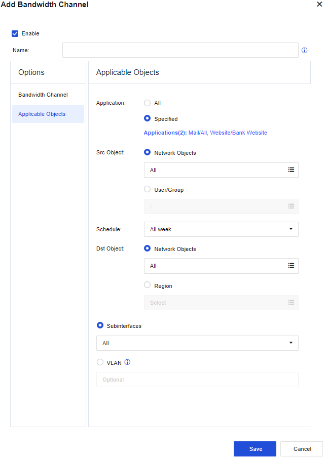
Application: Set the app category.
All: Indicate that it is valid for all data types.
Custom: Select a specific app category.
Click Select Application. In Select Application dialog box that appears, select the Application category.
In this example, the P2P-related data and the download data of downloading tools shall be subject to bandwidth management, and you can select Download Tools/All, P2P/All, and P2P Stream Media/All. In addition, you may also select Website Type and File Type. The former controls the data access to certain types of websites, whereas the latter controls the types of files downloaded via HTTP and FTP protocols. Confirm whether the range selected in Selected is correct. Click Save to complete the settings of applicable applications.
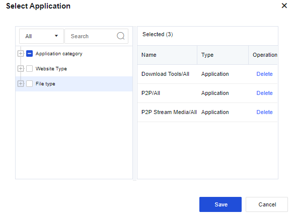
Src Object: Set the network objects and user groups for which the channel is valid. The applicable object can be either IP address-based or user-based. In this example, to guarantee the bandwidth for all users in the Marketing Department, select User/Group. In the Groups section, select the required group path. In the Current Group section, select Group and User. In the Selected Groups and Users section, view the list of selected users and user groups. After you select Applicable Objects, click Save to complete the settings.
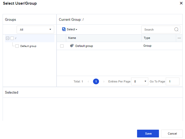
Schedule: Set the effective time of this channel.
Destination: Set the rules for the destination IP address or Region.
Subinterface: Set the subinterface to which the traffic channel is applicable.
VLAN: Set the VLAN to which the traffic channel is applicable.
The following page appears after the preceding parameters are set.
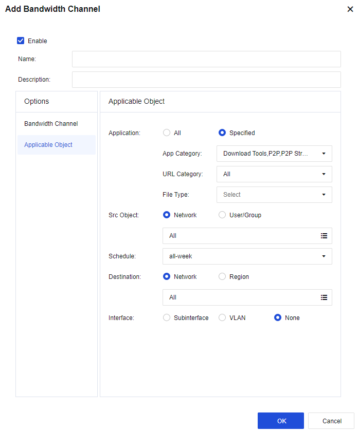
After setting, click OK to complete the settings for the limited channel.
- After you click OK, the set channel will appear on the Bandwidth Channel tab. The limited channel is configured.
Exclusion Rules
The exclusion rule sets some types of data that do not match any traffic control channels. The purpose is to exclude part of the data from the traffic control policy. For example, when the device is deployed in network bridge mode and the DMZ of the front-end firewall is connected to some servers, there is no need to control the traffic of data accessing this part of servers on the LAN. This is because the data does not go through the internet and is not subject to the limitations on the internet bandwidth. In that case, set an exclusion rule for the applications and IP addresses of these servers.
Exclusion Rule User Setting
For example, the device is deployed in network bridge mode, and the DMZ of the front-end firewall is connected to some servers. In this case, exclude the data accessing the servers.
- Go to Objects > Network Objects, create a new IP group, and add the IP address to be excluded.

- Go to Policies > Bandwidth Management > Bandwidth Channel > Exclusion Rules, and click Add to add the exclusion rule.
- Set the exclusion rule. Enter the name of the rule, select All for the App Category parameter and select Server set in Step 1 for the Destination parameter.
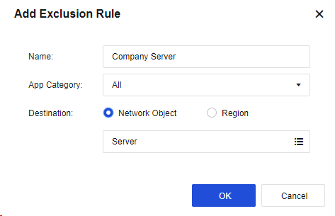
- Click OK to complete the settings.
The exclusion rule can also exclude those going to certain regions from bandwidth management.
Link Settings
Links
The link shows the current virtual lines. It is used to establish a correspondence between the device’s physical network interfaces and the target lines to be called on the Bandwidth Channel tab, specifying the interface (target line) for outgoing data that can match the traffic control channel. Click Add, and set the following parameters in the Add Link dialog box.
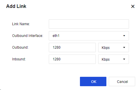
Link Name: Enter the name of the link.
Outbound Interface: Specify the interface for outbound data that can match the virtual line. You can only select a WAN interface.
Outbound: Set the outbound bandwidth of the physical line according to the actual bandwidth of the interface. Otherwise, the bandwidth management result may be unsatisfactory.
Inbound: Set the inbound bandwidth of the physical line according to the actual bandwidth of the interface. Otherwise, the bandwidth management result may be unsatisfactory.
If there are multiple WAN interfaces requiring bandwidth management, you need to define multiple virtual lines. Click Add to continue adding other virtual lines.
Notice:
After defining the virtual line(s), set the corresponding virtual line rules to call the virtual line(s). Otherwise, the settings of the bandwidth channel will be invalid.
Link Policy
Link Policy is necessary for bandwidth channels to be effective. Different link policies can be matched based on different protocols, LAN and WAN ranges, and outbound interfaces.
Go to Policies > Bandwidth Management > Link Settings > Link Policy, and click Add. Then, the Add Link Policy dialog box appears, as shown in the following figure.
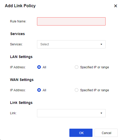
Services: Specify the protocol for packets. The protocol types include TCP, UDP, and ICMP. If there are other types, select others, and enter the protocol number range in the Protocol Number field.
LAN Settings: Set the rules for source IP address. The IP address includes IPv4 and IPv6. Enter the specific IP address or IP range.
WAN Settings: Set the rules for the destination IP address. The IP address includes IPv4 and IPv6. Enter the specific IP address or IP range.
Link : Set the virtual line to which the packets matching this virtual line rule will match, i.e., the interface from which the packets will be forwarded.
The bandwidth channel for a virtual line will be valid only when the virtual line becomes the destination line of a virtual line rule.
Authentication
The section describes the definition, authentication method, and usage of user management and user authentication.
User Authentication Status
To manage the authenticated online users, as shown in the following figure.
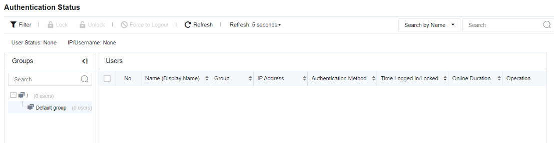
You can see the details of authenticated online users on this page, including the login name (display name), group, IP address, authentication method, time logged in/locked, online duration, and operation.
| Function | Note |
|---|---|
| Filter | The filter conditions include user status and object options. User Status is classified into All, Locked, and Active. The Object includes the Username and IP options. |
| Lock/Unlock | Select one or more users, click Lock to lock the users so that they cannot access the network, and set the point in time for locking. They can access the network normally after the set time is exceeded. Select the unlocked user, and click Unlock to unlock the user so that the user can access the network normally. |
| Force to Logout | The administrator can force online users to log out, but it does not apply to the users that do not need authentication or temporary users. |
| Search | Locate by searching for the specified user with login name or IP address. |
Table 17: User Authentication Function
Local Users
To manage all users accessing the internet. The user refers to the subject "who" accesses network resources and is the important identifier of online activity.
On the Group/User page, the administrator can manage online users in a unified manner. Users on Network Secure include online users and accessed users:
- Online user
It refers to the subject who accesses network resources, such as the internal staff at headquarters. The online users can directly access the network resources via Network Secure.
- Accessed user
It refers to the subject who accesses network resources, such as the internal staff at branches and staff on business trips. The accessed users shall access the Network Secure via SSL VPN, IPSec VPN, or PPPoE before accessing the network resources of headquarters.
Group/User
To realize user-based management, it is necessary to authenticate users who access the network to manage all users’ online behaviors.
User Type
- Based on the user source, the users can be classified into the following types:
-
Automatically discovered and created by the device.
-
Manually created by the administrator.
-
Imported from the CSV file.
-
Imported from the external LDAP server.
-
Imported after scanning the computer on the network.
- Based on the authentication method, the users can be classified into the following types:
-
Open authentication (binding IP/MAC).
-
Local password authentication.
-
External password authentication.
-
Single sign-on (combined with the external authentication system for authentication).
Group/User
To view users or groups that already exist on the device, select the user group to be viewed in the Groups pane. The Members page on the right shows the user group’s information, including the group path, description, group information, etc.
Members: On this page, you can view the details of all subgroups and users, including the group path, binding information (IP and MAC addresses bound to the user), expiration date (user), description, status (enabled or disabled), etc. You can also decide the information to be displayed by selecting the columns.
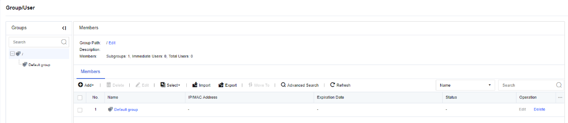
Select: To quickly select the users and user groups on the current page or all pages. Click Select. Then, the following options appears.
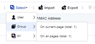
Search: To quickly find a user or user group. Click Search and select Name, IP Address, or MAC Address. Enter the content in the search box and press Enter to search.
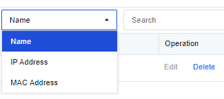
Advanced Search: Click Advanced Search, which is only applicable to search users. When you need to query a user through multiple search terms, you can select Advanced Search. The search terms include Basic Search Terms and Other. When you set multiple search terms, the terms follow the AND relation, which means all the terms shall be met.
The Basic Search Terms section includes Username, IP, and MAC address. These parameters are optional.
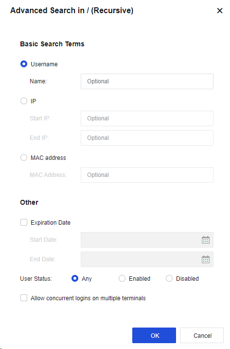
The Other section includes Expiration Date, User Status, and Allow concurrent logins on multiple terminals.
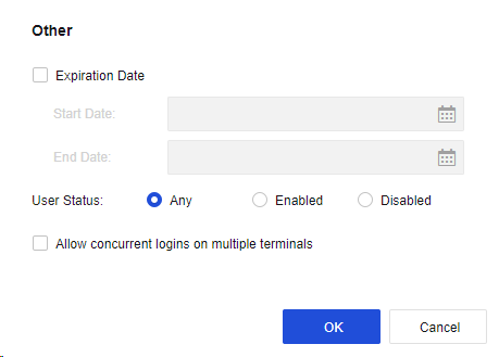
Group/User Management
The administrator can add, delete, batch edit, import, or export user groups and users.
| Function | Note |
|---|---|
| Delete | If you need to delete the unnecessary group or user, select the group or user to be deleted on the Group/User page and select Delete. If you associated the user or group, the user or group cannot be deleted directly. The user or group can be deleted only after the reference relationship is removed. |
| Edit | Batch edit differs from single-user edit in the editable attributes. Batch edit can be used to edit multiple users or groups. When editing users in batch, you cannot set the endpoint binding in the advanced attribute, i.e., IP and MAC binding, because this option is unique and cannot be set when you edit multiple users. |
| Import/Export | It can be used to import or export the data of a group or user to (from) the device. You can import users from a CSV file, and import display name, group, password, IP address range allowed to log in, public account, a custom attribute, etc. at the same time. A user group will be created automatically if the specified group to which the user is imported does not exist. Select the groups and users to be exported. The user group containing no user cannot be exported alone. |
| Advanced Search | Search terms and ranges: IP and MAC address can be set for filtering. Other can be customized for searching. |
| Move To | You can move local users and user groups to change their positions. The existing users or groups can be moved to another group. After a successful move, the users are moved from the original group to the destination group and use the internet access policy of the destination group. Common administrators may only have administrative permission for part of the groups. Therefore, they cannot move the users or groups to a user group beyond their administrative permission. |
Table 18: Description of Group/User Management Functions
Add User or Group
Add User
When you add a user, you can select Single User and Multiple Users.
To add a user, set the username, group, password, IP/MAC address, and other attributes, but not the authentication method. The authentication method of LAN users is set by going to Policies > Authentication > User Authentication > Authentication Policy and setting the IP or MAC address. The authentication method is used by the device to identify users.
Add Subgroup
The default group is the root group, and cannot be deleted or edited. All new groups are subgroups of the root group. The root group is the first level group, the new group under the root group is the second level group, and so on. The local group supports an organizational structure with up to 16 groups, including the root group. Such design is more consistent with the organizational structure of the Company and is convenient for management. For example, add an engineering group under the root group by performing the following steps:
- In the Groups pane, select the user group to which the subgroup will be added, and go to the management page on the right. On the Members page, click Add and select the type of group to be added.
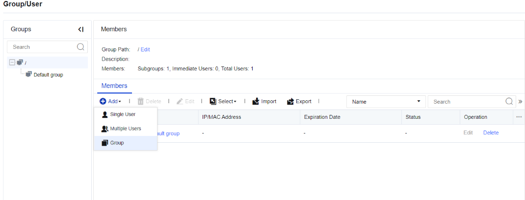
- In the Add dialog box, enter the name of the user group in the Group Name field. Specify the description of the user group in the Description field.
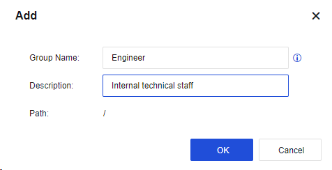
- Click OK. The subgroup is added.
Common Configuration Examples
Example 1
All PCs in the enterprise LAN 192.168.1.0/255.255.255.0 network segment use the username and password authentication method. A new user (common user) is added to the engineering group, authenticated based on username and password, bind unidirectionally to the IP range (i.e., the IP range that limits login) 192.168.1.2–192.168.1.100, and allowed concurrent logins on multiple terminals.
- The enterprise requires that all PCs in the 192.168.1.0/255.255.255.0 segment shall be authenticated based on username and password. Therefore, the first thing to do is to set the authentication method of users in this network segment.
Go to Policies > Authentication > User Authentication > Authentication Policy, and set the authentication policy. Set the IP or MAC address range of this user. Select SSO/Local or external password authentication in the Authentication Method section. Before setting the authentication policy, set the authentication zone. This example shows you how to select the authentication zone of LAN, as shown in the following figure. For more information about the zone, see Chapter 5.2 Zones.
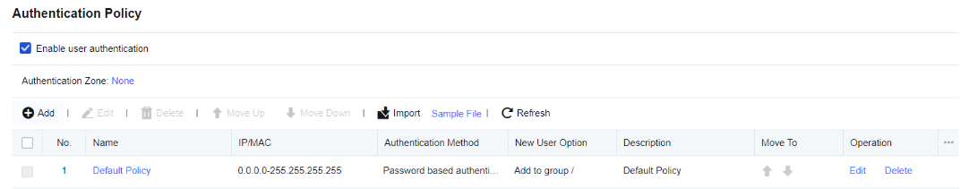
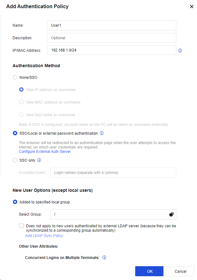
-
In the Groups pane, select the user group to which the user will be added, and go to the management page on the right. On the Members page, click Add and select Single User.
-
In the Add Single User dialog box, select Enable and set the Name, Description, Display Name and Add to Group parameters.
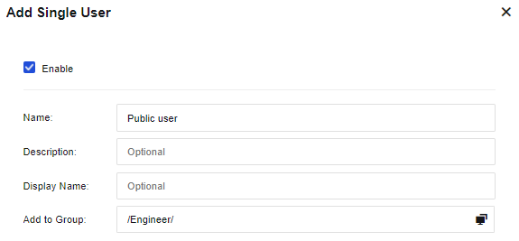
- On the User Attributes tab, set the user authentication method, public account, and expiration date. Select Local password and enter the user login authentication password in the Password field.
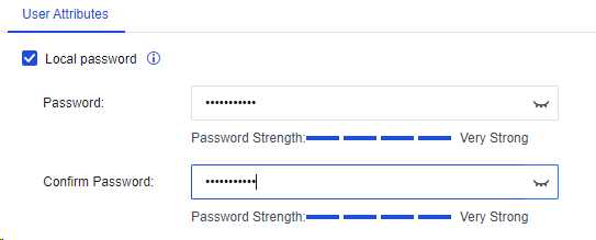
Bind IP/MAC: Bind the user to an IP/MAC address. In this example, the unidirectional binding IP range (i.e., the IP range that limits login) is 192.168.1.2–192.168.1.100.
Click Binding Mode. Select Unidirectional binding between a user and an address in the Binding Mode dialog box.
Select IP Address and enter 192.168.1.2-192.168.1.100 in the field.
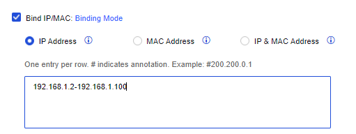
Allow concurrent logins on multiple terminals: Set whether concurrent logins on multiple terminals are allowed for the user authenticated based on username and password. If this option is selected, concurrent logins on multiple terminals are allowed. In this example, this option is selected as two users are allowed to log in concurrently.
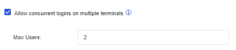
Select Show logout page if users are authenticated based on password. This option is for the users authenticated based on username and password, and a logout page appears after the users logged in.
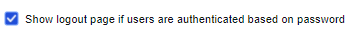
Select Auto-log out users who are idle for a specified period of time to set an idle time so that users who are idle beyond this period will be logged out automatically.
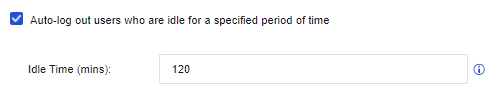
Expiration Date: Set the expiration date of the user.

-
After editing user attributes, click OK. Then, the user is added.
-
When a user in the corresponding network segment opens a webpage, the webpage is redirected to the authentication page of the device. Enter your username and password and click Log In. If the username and password are authenticated to be valid and conform to the rule of bound IP addresses, the authentication is successful.
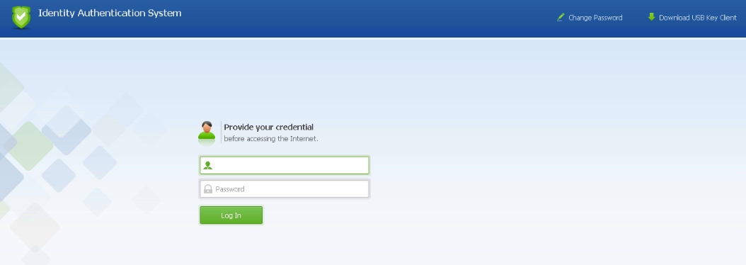
If the username and password are valid but the IP address for login is not in the bind IP address range, the authentication fails.
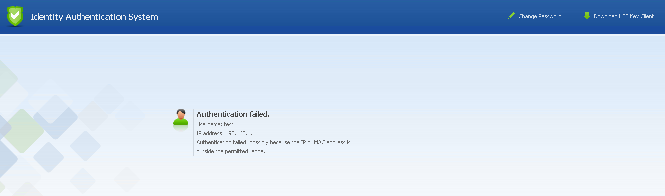
Notice:
Bind IP/MAC: Two binding modes include unidirectional binding and bidirectional binding.
Bidirectional binding between a user and an address: The user can only use the specified address for authentication, and this user can only use this address.
Unidirectional binding between a user and an address: The user can only use the specified address for authentication, but other users can also use this address for authentication.
Example 2
All PCs in the enterprise LAN 192.168.1.0/255.255.255.0 network segment use the username and password authentication method. A new user (Lee Engineer) is added to the engineering group, authenticated based on username and password, bound bidirectionally to the IP/MAC address 192.168.1.117/00-0C-29-7F-0B-47. (This user must use this IP/MAC address for authentication, while other users cannot.)
The enterprise requires that all PCs in the 192.168.1.0/255.255.255.0 segment shall be authenticated based on username and password authentication. Therefore, the first thing to do is to set the authentication method of users in this network segment.
- Go to Policies > Authentication > User Authentication > Authentication Policy, and set the authentication policy. Set the IP or MAC address range of this user. Select SSO/Local or external password authentication in the Authentication Method section. Before setting the authentication policy, set the authentication zone. This example shows you how to select the authentication zone of LAN, as shown in the following figure.
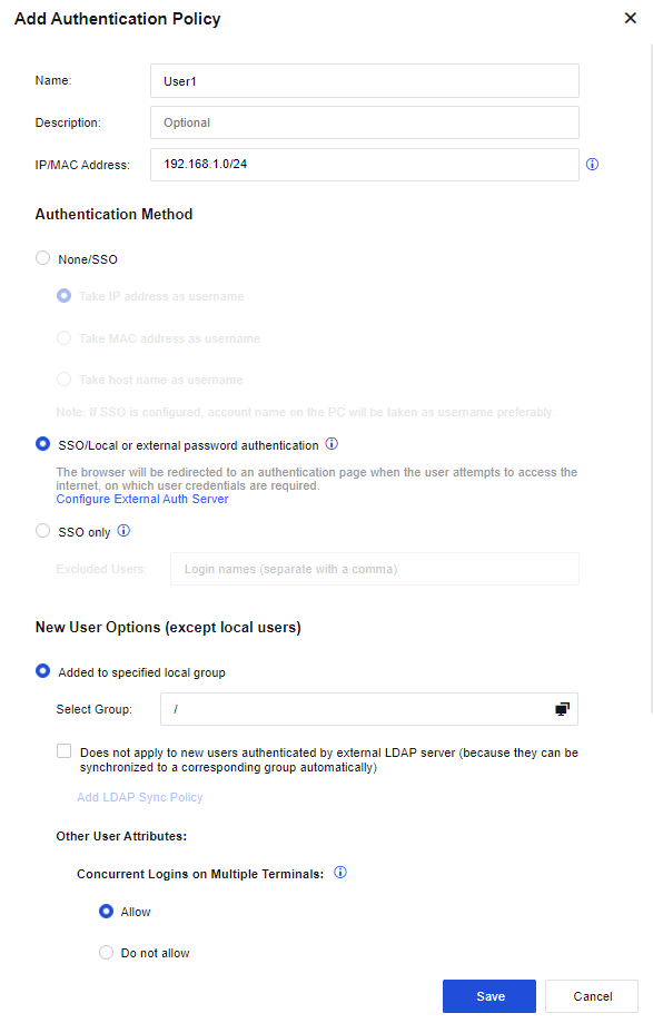
-
In the Groups pane, select the user group to which the user will be added, and go to the management page on the right. On the Members page, click Add and select Single User.
-
In the Add Single User dialog box, select Enable and set the Name, Description, Display Name, and Add to Group parameters.

- On the User Attributes tab, Select Local password and enter the user login authentication password in the Password field.

Bind IP/MAC: Bind the user to an IP/MAC address. In this example, the IP/MAC address of bidirectional binding is 192.168.1.117/ 00-0C-29-7F-0B-47. (This user must use this IP/MAC address for authentication, while other users cannot).
- Click Binding Mode and select Bidirectional binding between a user and an address in the Binding Mode dialog box. Select IP & MAC Address, and enter 192.168.1.117 (00-0C-29-7F-0B-47) in the field.
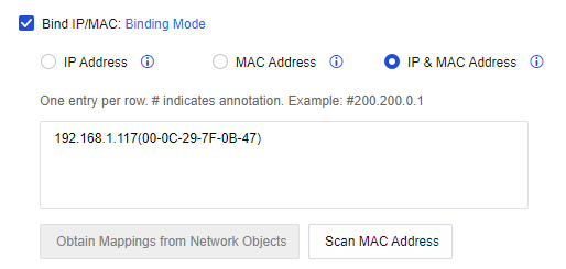
The user is considered a private account by default because it is only bound to a single IP/MAC address.
Select Show logout page if users are authenticated based on password. This option is for the users authenticated based on username and password, and a logout page appears after the users logged in.

Select Auto-log out users who are idle for a specified period of time to set an idle time so that users who are idle beyond this period will be logged out automatically.
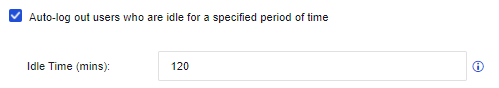
Expiration Date: Set the expiration date of the user.
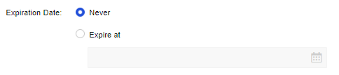
-
After editing user attributes, click OK. Then, the user is added.
-
When a user in the corresponding network segment opens a webpage, the webpage is redirected to the authentication page of the device. Enter your username and password and click Log In. If the username and password are authenticated to be valid and conform to the rule of bound IP addresses, the authentication is successful.
If the username and password are valid but the IP/MAC address for login is not the bound IP/MAC address, the authentication fails. The prompt message is as follows.
If other users use this IP/MAC address to authenticate, the Authentication Failed page will also appear.
Notice:
If users from the addresses that require no authentication are set under Policies > Authentication > User Authentication > Authentication Policy, the users can directly access the internet without entering the username and password. In this case, the device identifies the user based on the IP address, MAC address, or hostname. The common settings are:
- When creating a user, bidirectionally bind the user to an IP/MAC address. Because there is a one-to-one correspondence between the IP/MAC address and user during the bidirectional binding, the user can be identified based on the IP/MAC address.
- Go to Policies > Authentication > User Authentication > Authentication Policy, set Authentication Zone to None, and take the IP address, MAC address, or hostname as the username. For authentication of LAN users, their usernames are matched based on the IP address, MAC address, or hostname.
Example 3
Set a user as the supervisor in the "/Engineer" group. This user requires no authentication. Bidirectionally bind the user and the IP/MAC address of the supervisor’s PC. In this way, only the supervisor’s PC can use this account to access the Internet. The IP/MAC address of the supervisor’s PC is 192.168.1.117 (00-0C-29-7F-0B-47).
- Go to Policies > Authentication > User Authentication > Authentication Policy, set the authentication policy. Set the IP or MAC address range of this user. Select None/SSO in the Authentication Method section. Before setting the authentication policy, set the authentication zone. This example shows you how to select the authentication zone of LAN, as shown in the following figure.
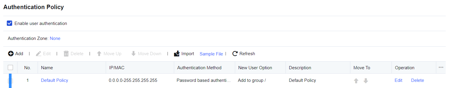
-
In the Groups pane, select the user group to which the user will be added, and go to the management page on the right. On the Members page, click Add and select Single User.
-
In the Add Single User dialog box, select Enable and set the Name, Description, Display Name, and Add to Group parameters.
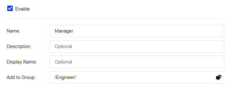
-
Select Bind IP/MAC to bind the user to an IP/MAC address. In this example, the IP/MAC address of bidirectional binding is 192.168.1.117/ 00-0C-29-7F-0B-47. (This user must use this IP/MAC address for authentication, while other users cannot).
-
Click Binding Mode and select Bidirectional binding between a user and an address in the Binding Mode dialog box. Select IP & MAC Address, and enter 192.168.1.117 (00-0C-29-7F-0B-47) in the field.

The user is considered a private account by default because it is only bound to a single IP/MAC address.
Expiration Date: Set the expiration date of the user.

-
After editing user attributes, click OK. Then, the user is added.
-
When accessing the internet through the device, verify whether the IP and MAC addresses are valid. If so, the authentication is successful, and no authentication page appears on the client. If the IP/MAC address is not the bound one, the authentication fails. No prompt message appears, but the client cannot access the internet.
User Import
On the User Import page, you can import users at a time, and you can select Import from CSV File, Import by IP Scan, or Import from External LDAP Server.
-
Import from CSV File: You can import users from a CSV file, and import the display name, authentication method, IP/MAC address, and password at the same time. A user group will be created automatically if the specified group to which the user is imported does not exist.
-
Import by IP Scan: When importing users bound to IP/MAC addresses, you can select this option to scan the MAC addresses of LAN users, which is convenient to import such users. By default, users imported this way belong to the root group and require no authentication. Their bound IP/MAC addresses and usernames are device names generated after the scan. You cannot import a user having an IP address that conflicts with those bound to existing users.
-
Import from External LDAP Server: To synchronize users on the LDAP server to the device. It supports importing users from the Microsoft Active Directory server. When the domain users are imported, the security groups of the domain server are imported in the form of user groups and the users are imported to the corresponding security groups.
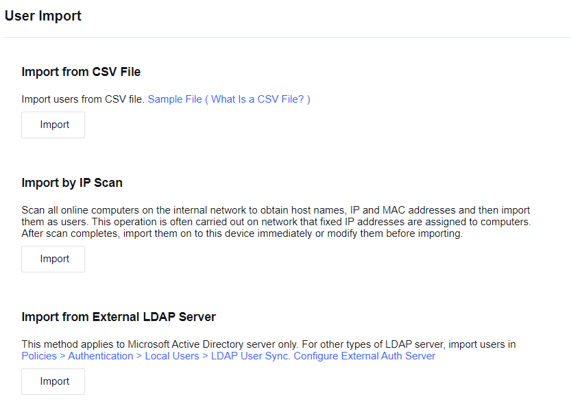
Import from CSV File
You can import users from a CSV file, and import the display name, authentication method, IP/MAC address, and password at the same time. A user group will be created automatically if the specified group to which the user is imported does not exist.
The CSV table has a very simple format that can be edited and saved by almost all spreadsheet software. For example, Microsoft Excel can edit this file and easily convert XLS tables to CSV tables.
Note:
As the CSV file is very simple and does not support setting column widths, fonts, colors, and other attributes, in order to facilitate editing and managing users, you can edit user information in an Excel table first, and then convert it to the CSV file for importing.
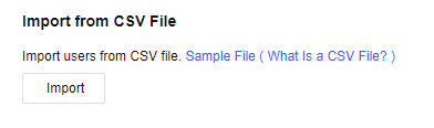
- Import the format sample of the user. You can click Sample File (What Is a CSV File?) to download it. Set user information to be imported by the format in the sample file.
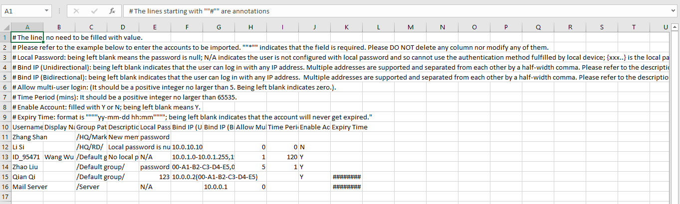
- Import the set CSV file. Click Import and select the file to be imported in the Import CSV File dialog box.
If you select If a user group does not exist, it will be created automatically, a user group will be created automatically if the specified group to which the user is imported does not exist. Otherwise, such a group will not be created, and the user will be imported to the root group by default.
If you select Proceed and overwrite an existing one for If a user already exists, when the user list already contains users with the same usernames, the attributes of the users will be updated. If you select Skip and do not overwrite an existing user, user attributes will not be updated and the import of this user will be skipped in the same situation.

Import by IP Scan
To scan the MAC addresses of the corresponding IP addresses and import the scanned users named by their respective device names. These users are imported to the root group by default without authentication, and their IP and MAC addresses are bound.
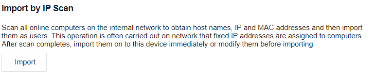
Configuration case of IP scan
Scan the PCs on the LAN within the range of 192.168.1.100-192.168.1.200 and import them to the user list.
- Select Import by IP Scan. Click Import. Specify IP Range and click Save.

- Click Save to scan the PCs within the range of 192.168.1.100-192.168.1.200. Only live PCs in that range will be returned. Username is the name of the scanned PC.
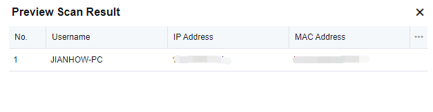
- Click Import to directly import the users to the device. In the dialog box displayed, select Create a group if no such group on local device to create the specified user group automatically if it does not exist. If this option is not selected, users will be imported to the root group by default. If a user already exists, select Proceed and overwrite an existing one to update the attributes of this user if it is on the user list, or select Skip and do not overwrite an existing user to not to update the attributes of this user and skip import.
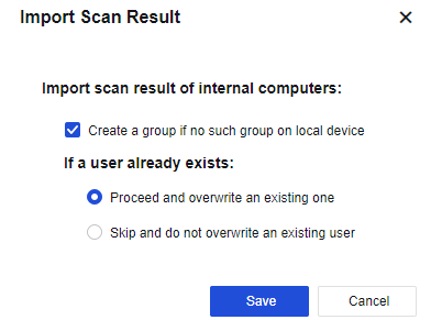
Click Download to Edit to save the user information locally as a CSV file to modify the scan results and user attributes as required. Click Import from CSV File to import the modified file.
- Click Submit. The users are imported to the root group.
Notice:
The username is the device name obtained by the NetBIOS protocol on the PC logged in to the control panel. Username unknown indicates that no device name is found. In this case, check the following:
Whether the NetBIOS protocol is enabled on the target PC.
Whether the target PC has configured multiple IP addresses.
Whether the NetBIOS protocol has been filtered out by the firewall on the target PC.
Whether the NetBIOS protocol has been filtered out by a device in the network path.
Import from External LDAP server
To synchronize users on an external LDAP server to the device. It applies to the Microsoft Active Directory server only. For other types of LDAP servers, please import users in Policies > Authentication > Local Users > LDAP User Sync.
To import users from an LDAP server, configure the LDAP server first. (For setting details, see Policies > Authentication > User Authentication > External Auth Server. For more details, refer to part 6.6.2.3 LDAP User Sync.
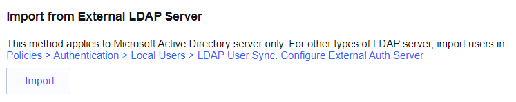
Note:
- Controls must be installed for the import. Therefore, please use an IE browser to log in to the console.
- The device shall connect to the TCP389 port of the LDAP server properly to read and import the users on the LDAP server.
LDAP User Sync
LDAP User Sync is used to synchronize users, OUs, and security groups from the domain server to the device. When Auto Sync is enabled, data is automatically synchronized from the domain server to the device once a day, at a random time between 0:00 AM and 6:00 AM.
LDAP User Sync includes two modes: Sync by OU and Sync by security group (AD domain only).
Sync by OU: Applicable to all types of LDAP servers. In this mode, the OUs, as well as their structures, will be synchronized to the device as user groups from the LDAP server. Users remain in the same OU group after synchronization.
Sync by security group (AD domain only): Only applicable to the Microsoft LDAP server, i.e., the AD domain. In this mode, security groups on the AD domain server are synchronized to the device as user groups. Security groups have no hierarchy and therefore, are synchronized at the same level.
Add a Synchronization Policy
Synchronization policy is used to set synchronization parameters, based on which LDAP synchronization is implemented.
Sync by OU
Applicable to all types of LDAP servers. In this mode, the OUs, as well as their structures, will be synchronized to the device as user groups from the LDAP server. Users remain in the same OU group after synchronization.
LDAP User Sync Case
An enterprise needs to synchronize the organizational structure of the LDAP server with that of the device while maintaining continuous synchronization. To achieve this, LDAP User Sync must be configured on Network Secure.
-
Set the LDAP server to be synchronized by specifying the IP address, port, login username, password, etc. For details, see part 7.6.3.3 External Authentication Server.
-
Go to Policies > Authentication > Local Users > LDAP User Sync, click Add, and set synchronization parameters in the Add Sync Policy dialog box.
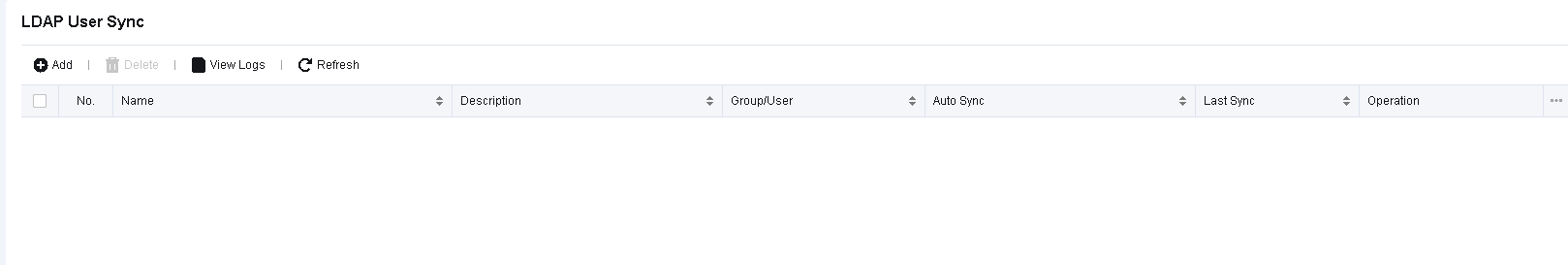
- Specify Name, Description, Sync Mode, and Auto Sync. Select Sync by OU for Sync Mode, and Enabled (once a day) for Auto Sync. Automatic synchronization is implemented once a day.
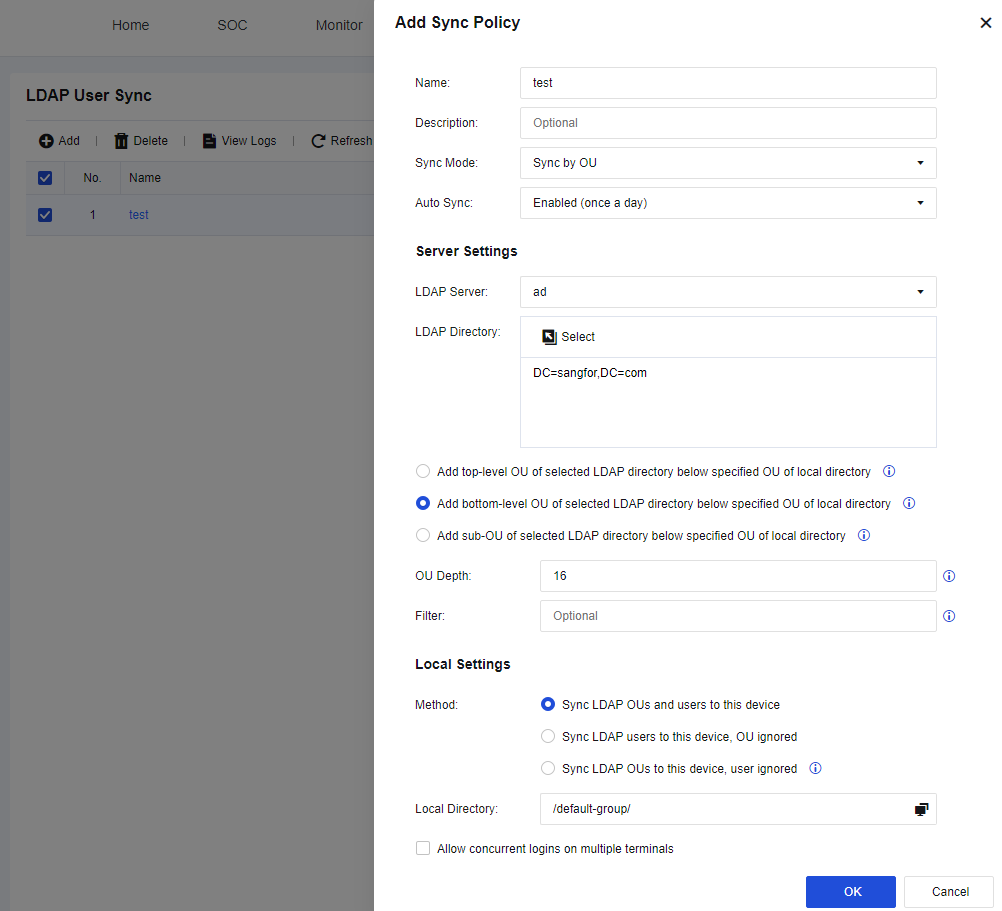
- In Server Settings, set information of OUs on the LDAP server to be synchronized.
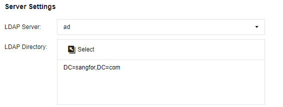
LDAP Server: Enter the LDAP server to be synchronized. In this example, the server configured in Step 1 is selected.
LDAP Directory: Specify the OUs to be synchronized on the LDAP server. Click Select to select the OUs to be synchronized in the Select OU dialog box. Click Save.
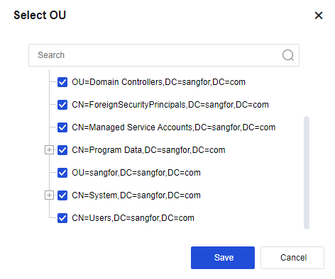
Add top-level OU of selected LDAP directory below specified OU of local directory: When selected, the root domain on the LDAP server will also be synchronized as a group, and the OUs synchronized are its subgroups.
Add bottom-level OU of selected LDAP directory below specified OU of local directory: When selected, the synchronization starts from the selected OU.
Add sub-OU of selected LDAP directory below specified OU of local directory: When selected, the synchronization starts from the sub-OU of the selected OU. The selected OU and its affiliated users will not be synchronized to the device.
OU Depth: Specify the depth of the imported OUs. The value is 10 in this example, indicating that only sub-OUs up to level 9 can be synchronized as user groups to the device. However, users of OUs lower than level 9 can still be synchronized to the device as users under level-9 OUs.
Filter: Specify the filter parameters for synchronization.
- In Local Settings, set Method and Local Directory, and select whether to enable Allow concurrent logins on multiple terminals.
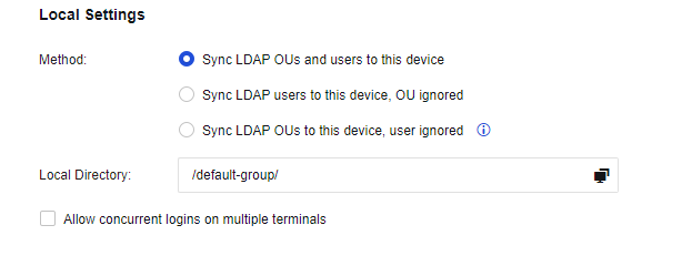
Method: Whether to synchronize OUs and users. Select an option based on requirements.
Sync LDAP OUs and users to this device: Synchronize OUs as user groups to the device and OU users to the OU user groups.
Sync LDAP users to this device, OU ignored: Synchronize OU users instead of OUs to the device.
Sync LDAP OUs to this device, user ignored: Synchronize OUs but no OU users to the device as user groups. In this example, select Sync LDAP OUs and users to this device to synchronize both OUs and users.
Allow concurrent logins on multiple terminals: The domain account synchronized to the device is a public account by default and can be logged in on multiple PCs. If this option is not selected, the user is a private account and can be logged in on a single PC at a time.
Local Directory: Select an existing group on the device, to which synchronized OUs will be subgroups. In the Select OU dialog box, select the corresponding group.
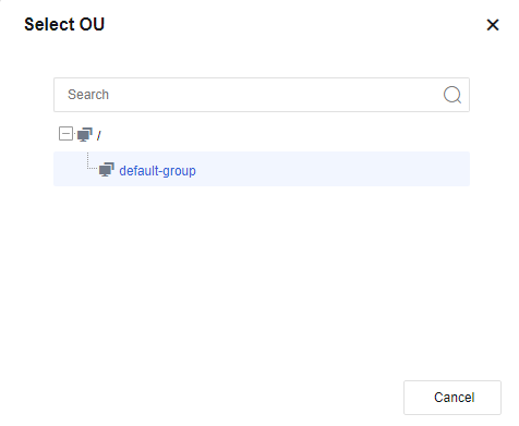
- Click OK to complete setting the policy. The added synchronization policy is displayed on the LDAP User Sync page. Click Sync Now to perform a synchronization immediately. Or wait for the daily automatic synchronization.
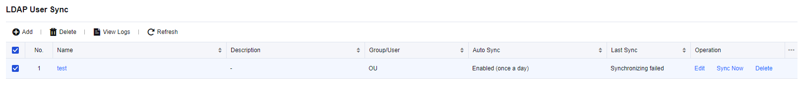
- Go to Policies > Authentication > Local Users > Group/User to view the synchronization results, as shown in the following figure. The imported OUs and users are consistent with those on the LDAP server.
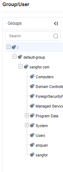
If the names of OUs or users to be synchronized duplicate existing user groups or users on the device, the synchronization will fail.
Delete a Synchronization Policy
When a synchronization policy is unwanted, you can delete it. Specifically, go to the LDAP User Sync page, select the synchronization policy to be deleted, and click Delete. The deletion of a synchronization policy will not affect the groups and users already synchronized to the device.
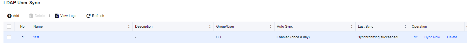
View Logs
A synchronization log is generated every time the device synchronizes OUs or users from the LDAP server to inform you of the synchronization status. Click View Logs. In the Sync Logs dialog box, select and download the synchronization log you want to view by clicking the corresponding name.
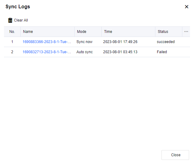
User Authentication
In this module, you can configure the user authentication parameters, including Authentication Policy, Authentication Options, and External Auth Server. Note that LAN users can still access the Internet even if the device does not enable user authentication. In this case, to protect LAN PCs, define IP addresses in objects to show user ranking and logs in IP addresses.
The authentication methods include the following types:
- Username/Password
Before network access, a terminal user is redirected to an authentication page to enter the correct username and password. You can authenticate either a local password or an external server password.
After the user enters the username and password, the system will first check whether the username and password are correct. Suppose the username is not found and an external authentication server is configured. In that case, the system will check whether the username and the password map those of the external authentication server.
Notice:
Local password authentication only applies when the Local Password is selected. Otherwise, the username and password are sent to the external authentication server for authentication.
- Single Sign-On
Single sign-on (SSO): This system can co-work with an identity authentication system on an organization’s network to identify the user using a certain IP address. In this way, the user will not be required to enter the username/password for Internet access, thus improving the user experience of accessing the Internet.
- Identification based on IP address, MAC address and hostname
The user is identified based on the source IP address/MAC address of the packet and the hostname.
-
Advantage: No authentication box will pop up in the browser for the user to enter the username and password upon network access. Therefore, the user will not perceive the existence of the device.
-
Disadvantage: It is impossible to identify the specific username, especially in a network where IP addresses are dynamically allocated. For this reason, user behaviors cannot map to specific users, preventing user-specific policy control.
Authentication Policy
If user authentication is enabled, all PCs in the authentication area will be authenticated before Internet access. Authentication Policy determines the authentication method of PCs on a given IP address/network segment/MAC address. In Authentication Policy, set the authentication method of LAN users and the policy of adding new users.
The administrator can delete, batch edit, enable and disable, import, move up/move down, filter, and select any authentication policy.
| Function | Note |
|---|---|
| Add | On the Authentication Policy page, click to add a new authentication policy. |
| Delete | On the Authentication Policy page, click to delete an authentication policy. |
| Edit | On the Authentication Policy page, select the authentication policy to be edited, and click the policy name. The Edit Authentication Policy dialog box is displayed. Modify the selected policy. Batch edit: Select multiple custom authentication policies to edit the applicable object instead of any other information. |
| Import | Click to select and import an authentication policy file. |
| Move Up/Move Down | As the policies are matched from top to bottom, you can select the corresponding policy, and click Move Up or Move Down to give priority to match the policies. |
Table 19: Authentication Policy Function
The authentication policies are matched one by one from top to bottom. You can re-prioritize them by using the move options. By configuring authentication policies, you can configure authentication methods depending on the network segments.
Authentication Method
A device can be authenticated in the following ways:
-
No authentication.
-
Password authentication (including local password authentication and external server authentication).
-
SSO: the above authentication methods are configured in Authentication Policy, and a single sign-on is configured in Authentication Options.
There are three authentication methods in the Authentication Policy: None/SSO, SSO/Local or external password authentication, and SSO only.
All three authentication methods include SSO. If SSO is selected in Authentication Options, the username on a PC will be preferably used to access the Internet after SSO authentication.
- None/SSO
If SSO is selected in Authentication Options, the username on a PC will be preferably used to access the Internet after SSO authentication.
If SSO is not selected in Authentication Options, the device identifies the user based on the source IP address and source MAC address of the packet and the hostname. In this mode, no authentication box will pop up in the browser for the user to enter the username and password upon Internet access. Therefore, the user will not perceive the existence of the device.
Create a user requiring no authentication:
-
Deselect Enable user authentication on the Authentication Policy page. When creating a user, bidirectionally binds the user to an IP/MAC address to form a one-to-one relationship so that IP/MAC-based authentication is possible. (Note that the IP/MAC address range set in Authentication Policy should include the bounded IP/MAC address.)
-
Deselect Enable user authentication on the Authentication Policy page, and take the IP address, MAC address, or hostname as the username. For authentication of LAN users, their usernames are matched based on the IP address, MAC address, or hostname.
- SSO/Local or external password authentication
When Enable user authentication is selected and this authentication method is used, the authentication procedure for network access is as follows if SSO authentication is not selected or fails:
a) The browser redirects the user to a page where the username and password must be entered before accessing the Internet. Assume that the username entered is "test" and the password is "password".
b) The system checks whether the user "test" is a local user. If the user exists and has a local password (that is, "Local Password" is selected in User Attributes), the system checks whether the user’s local password is a "password". If yes, authentication succeeds; if no, the authentication fails.
c) If there is no local user "test", or the user exists but does not have a local password, the system checks on the external authentication server whether the username and password are correct. If they are correct, the authentication succeeds; otherwise, the authentication fails.
Local authentication is before the external authentication.
- SSO only
If this option is selected, the address range specified in the policy must use SSO to pass authentication.
a) Set the Authentication Method of the specified network segment to SSO only.
b) On the Authentication Options page, enable SSO. For AD SSO, SSO should also be enabled on the domain server.
c) Set Excluded Users to exclude non-SSO users. These users enter usernames and passwords manually to complete authentication.
New user settings:
New users are those newly added to the device. According to Authentication Policy > New User Options (except local users), the device determines whether to add them automatically after mapping their IP or MAC address with those in the Authentication Policy.
Users who pass the authentication can be automatically added. These users include users requiring no authentication and named with IP address, MAC address, or hostname, as well as SSO/external password-authenticated users.
Three options are available for the administrator to add the new users: Added to specified local group, Added as guest account (not added to any local group), and No authentication for new users.
Select Authentication Zone
Before setting an authentication policy, specify the zones for which authentication will be enabled.
- Select Enable user authentication.
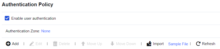
- Select the Authentication Zone.
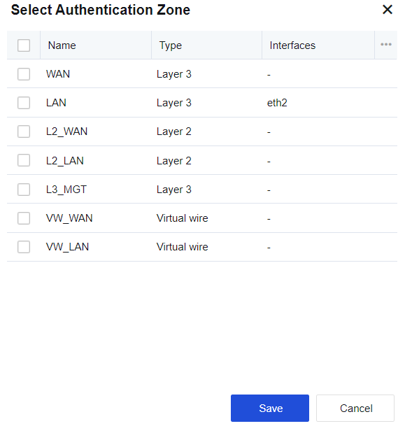
Click Save. The authentication zone is selected.
The authentication zone can be the area where the LAN interface is located. Zones are defined as LAN or WAN interface areas. For example, ETH2 is a WAN interface, while ETH1 is a non-WAN interface. Therefore, ETH2 is defined as in the WAN zone, while ETH1 is in the LAN zone.
Configuration Case 1 of Adding Authentication Policy
Configure LDAP server-based third-party password authentication for PCs within 192.168.1.0/255.255.255.0 of the Engineering Department. New users are automatically added to the "/engineer" group and their usernames are bidirectionally bound to IP addresses. Hence, there is a one-to-one correspondence between IP addresses and usernames. Users in other LAN network segments require no authentication and take IP addresses as usernames. New users are automatically added to the "/Default group". (The external LDAP server is taken as an example here. The setting steps are similar for other types of external authentication servers.)
-
Go to Policies > Authentication > User Authentication > Authentication Policy, click Add. In the Add Authentication Policy dialog box, click Configure External Auth Server and set the LDAP authentication server.
-
In the Add Authentication Policy dialog box, set the required parameters.
Name: Enter the name of the authentication policy (mandatory).
Description: Enter the description of the policy and supplementary information (optional).
IP/MAC Address: Enter an IP address, IP segment, or MAC address, which is the matching rule. If a user fails to pass the authentication when accessing the Internet via the device, the device will match the user to the corresponding Authentication Policy based on the IP or MAC address of the packets. In this example, set the value to 192.168.1.0/255.255.255.0.
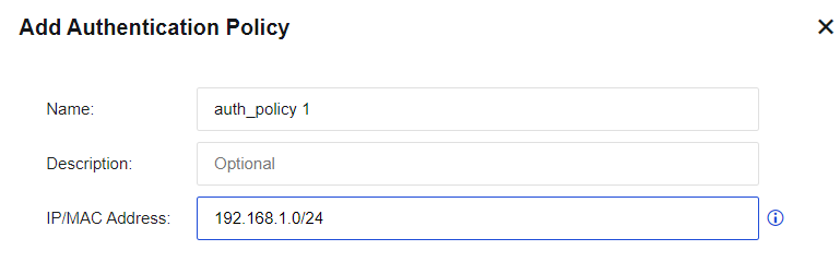
- Set Authentication Method to specify how to authenticate users that meet the matching rule.
Three authentication methods are provided in Authentication Method: None/SSO, SSO/Local or external password authentication, and SSO only. (For descriptions of the three authentication methods, see the overview in this chapter.)
This example exemplifies third-party server password authentication. Therefore, SSO/Local or external password authentication is selected.
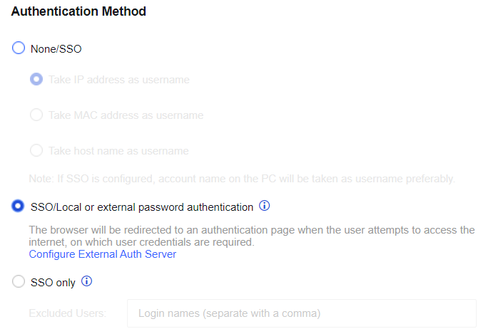
- Set New User Options (except local users) to configure settings for new users.
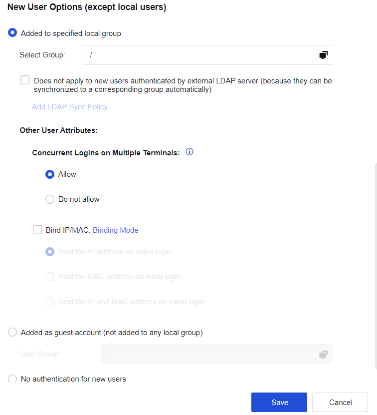
If Added to specified local group is selected, the user can be automatically added to the device’s user list. In Select Group, select the user group for the new user, and the user will automatically be added to this group. In this example, users are added automatically through third-party authentication to the /engineer group. Therefore, "/Engineer" is selected.
If Does not apply to new users authenticated by external LDAP server (because they can be synchronized to a corresponding group automatically) is selected, the user will be synchronized according to the LDAP synchronization policy and added to the corresponding group if a user uses LDAP third-party authentication or SSO, the related LDAP synchronization policy has been set on the device. This will render the setting in Select Group in the previous step invalid.
Other user attributes include Concurrent Logins on Multiple Terminals and Bind IP/MAC.
Concurrent Logins on Multiple Terminals: You can select either Allow or Do not allow. This setting is valid for users requiring authentication only.
Bind IP/MAC: Two binding modes, unidirectional and bidirectional.
Unidirectional binding between a user and an address: The user can only use the specified address for authentication, but other users can also use this address for authentication.
Bidirectional binding between a user and an address: The user can only use a specified address for authentication, and this address can only be used by this user.
In this example, Bidirectional binding between a user and an address and Bind the IP address on initial login are selected.
If you check Added as guest account (not added to any local group), new users will not be added to the user list. Instead, they can only access the Internet with the permission of casual users. Select a group from the User Group. The casual users can then access the Internet with permission from the specified group.
If you check No authentication for new users, new users are not allowed to be added, and the users not on the user list are not allowed to access the Internet if the authentication fails. They only have the permission allowed for users failing authentication, which is set in User Authentication > Authentication Options > Others.
- Set the authentication policy of users in other network segments. Users in other LAN network segments require no authentication and take IP addresses as usernames. New users are automatically added to the "/Default group". Edit Default Policy in Edit Authentication Policy dialog box.
Authentication Method: Select Take IP address as username in None/SSO.
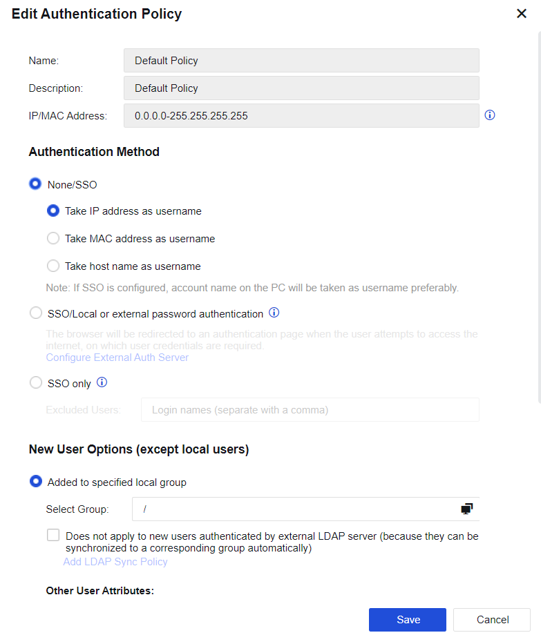
New User Options (except local users): Select Added to specified local group and "/Default group/".
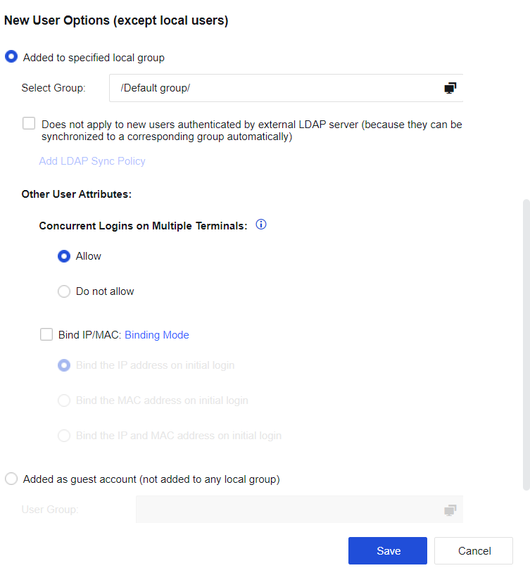
Authentication policies are matched from top to bottom. The two authentication policies in this example are sorted as follows.
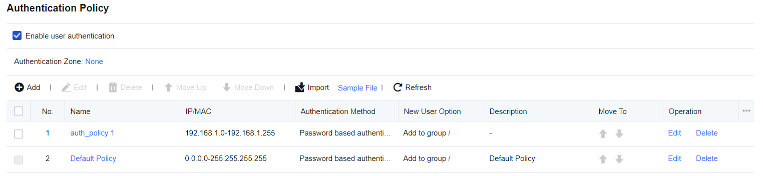
Configuration Case 2 of Adding Authentication Policy
PCs with LAN IP addresses residing in 192.168.2.1-192.168.2.255 are automatically added to the "/Marketing Dept" group as new users requiring no authentication. The usernames are the hostnames and are bidirectionally bound to MAC addresses.
-
In Policies > Authentication > User Authentication > Authentication Options > Obtain MAC By SNMP, set the option to obtain MAC addresses across three layers by SNMP.
-
On the Authentication Policy page, click Add to enter the Add Authentication Policy dialog box. Specify Name and Description.
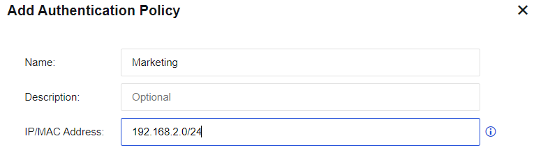
- Under the Authentication Method, select None/SSO and select the option Take host name as username.
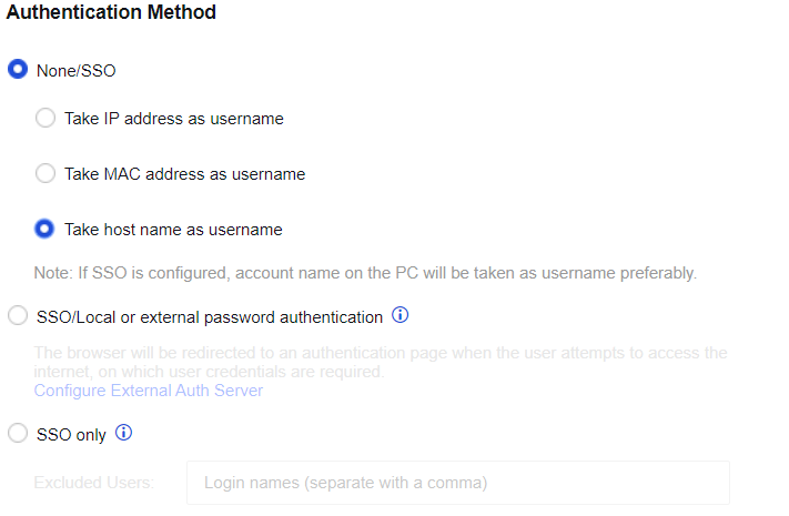
- In New User Options (except local users), select Added to specified local group and "/Marketing Dept" as the user group.
Select Bind IP/MAC and Bind the MAC address on initial login. In this example, the LAN spans three layers and you need to obtain the MAC address from the switch through the SNMP. Configure the setting in Policies > Authentication > User Authentication > Authentication Options > Obtain MAC By SNMP.
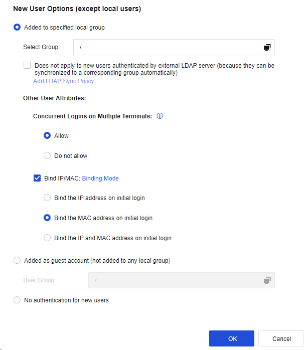
- Click OK to complete policy editing.
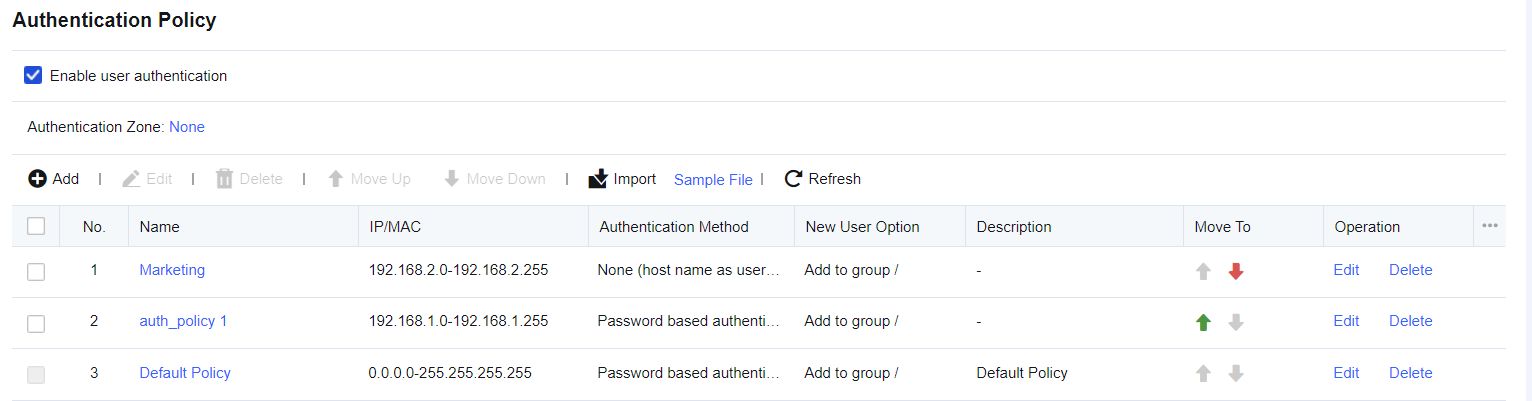
The name of a live PC is obtained by the NetBIOS protocol and may not be found sometimes. In this case, check the following:
-
Whether the NetBIOS protocol is enabled on the target PC.
-
Whether the target PC has configured multiple IP addresses.
-
Whether the NetBIOS protocol has been filtered out by the firewall on the target PC.
-
Whether NetBIOS protocol has been filtered out by a device in the network path.
Suppose the PC name cannot be obtained. In that case, the system will identify the PC as a temporary user and name it as Unknown Computer, which will only be displayed in the online user list and will not be added to the specified local group.
If one or more Layer 3 switches are installed between the online PC and the device, the real source MAC address cannot be obtained because of the change in the source MAC address of the online PC. To acquire the real source MAC address of an IP address, obtain the ARP table of the Layer 3 switch (gateway device directed by this PC) that is nearest to this PC via SNMP.
Configuration Case 3 of Adding Authentication Policy
PCs in the LAN segment 192.168.3.0/255.255.255.0 are authenticated based on the AD SSO. After passing the AD domain authentication in the login system and the device’s authentication, users in the AD domain can be synchronized to the device. If SSO fails on PCs in this network segment or the PCs do not log in to the domain, the IP address will be used as the username, no authentication will be required for Internet access, and the users will be added to "/Default group" automatically.
-
On the Authentication Policy page, click Add to enter the Add Authentication Policy dialog box. Click Configure External Authentication Server to add a external authentication server. After that, configure LDAP User Sync.
-
On the authentication policy, specify Name and Description.
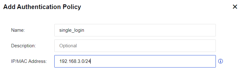
- Under the Authentication Method, select None/SSO and select the option Take IP address as username.
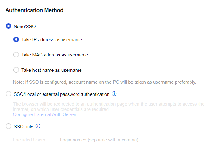
- In New User Options (except local users), select Added to specified local group and "/Default group/" as the user group. At this time, non-SSO users will be added to the default group and are subject to the default group’s Internet access policy.
Select Does not apply to new users authenticated by external LDAP server (because they can be synchronized to a corresponding group automatically), so AD SSO users will be added to the group set in the synchronization rule.
Note:
Bidirectional binding does not apply to this example. The reason is that a non-SSO user is automatically added as a new user and binds IP/MAC address bidirectionally. This IP/MAC address can only be used by this user, and SSO authentication will no longer be used. However, unidirectional binding is acceptable.
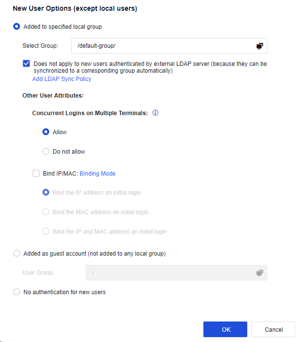
- Click OK to complete policy editing.
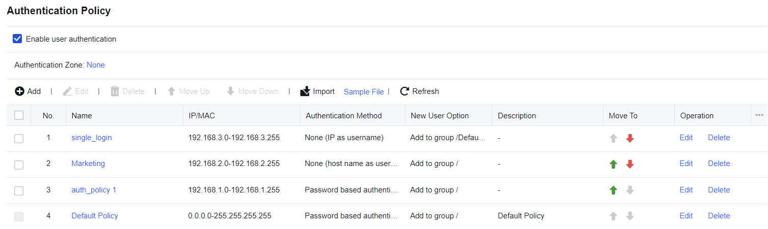
Authentication Options
Authentication Options is used to set configuration information related to user authentication on devices, including SSO Options, Auth Page Redirection, Authentication Conflict, Obtain MAC By SNMP, and Others.
SSO Options
For customers with third-party authentication servers to authenticate LAN users, SSO allows LAN users to pass both third-party server authentication and device authentication as well as obtain permission to access the Internet. The username and password used by the device are the same as those used by the third-party authentication server. SSO types supported by the device currently are AD AD SSO, Proxy SSO, POP3 SSO, and Web SSO. Those are basic SSOs. To use SSO, you need to configure users, authentication servers, and user authentication methods in Administrators, External Auth Server, and Authentication Policy, respectively.
AD SSO
AD SSO is acceptable in enterprises with Microsoft AD domain server presence for user management and where LAN users log in to the computer as domain accounts. After logging in to the domain, LAN users are considered to have passed device authentication. In other words, end users can log in to the domain to access the Internet without device authentication. AD SSO can be realized by distributing domain scripts or listening to packets of the login domain. AD SSO applies only to the Microsoft Active Directory (AD) domain.
Configuration of Domain Script Distribution Mode
Configure login (logon.exe) and logout (logff.exe) scripts for the domain server. Then, you can log in to or log out of the device by running the two scripts based on the issued domain policy.
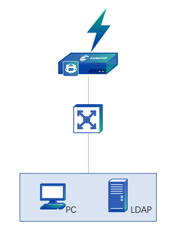
The data stream is as follows:
-
PC requests to log in to the domain.
-
The domain returns a successful login message to the PC.
-
The PC runs logon.exe and sends the message of a successful login to the domain to the Network Secure device.
Configuration Steps
-
Navigate to Policies > Authentication > User Authentication > External Auth Server to set the authentication AD domain service.
-
Enable SSO on the device, select the SSO mode, and set a Shared Key. Go to Policies > Authentication > User Authentication > Authentication Options > SSO Options > AD SSO to enter the editing page.
Select Enable AD SSO to enable the AD SSO.
If Receive login credentials from a login script running on your AD domain controller is selected, SSO will be implemented by issuing the domain script. Enter the shared key in Shared Key, as shown below.
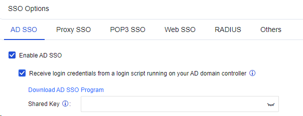
The Shared Key is used for encrypted communication between the AD domain server and the device and must be the same in login scripts. Click Download AD SSO Program to download the login and logout scripts to complete settings in Step 3 and Step 4.
Notice:
IAM11.0R2 and later versions are supported to synchronize authentication information to the Network Secure over port 1775.
- Configure the login script on the AD domain server.
a) After logging in to the domain server, open the Server Manager menu, as shown below:
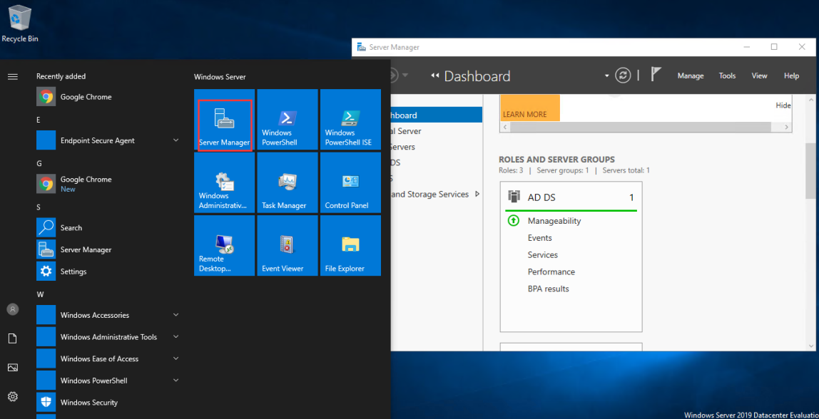
b) Go to Tools and select Group Policy Management.
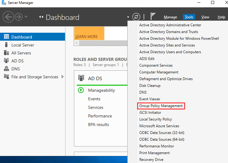
c) In the pop-up window, go to Group Policy Objects.
d) Right-click New to create a new GPO policy.
e) Edit the newly added GPO on the Group Policy Management Editor page. Click User Configuration > Policies > Windows Settings > Scripts (Logon/Logoff).
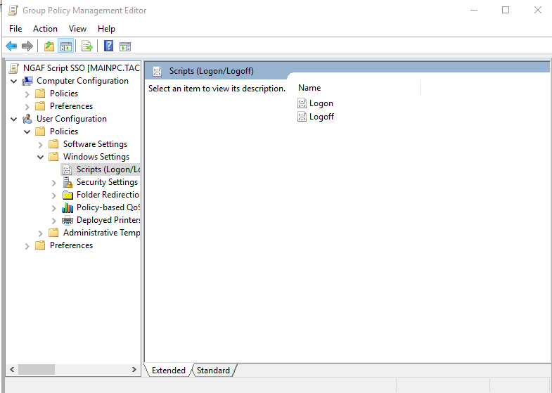
f) Double-click the Logon option on the right. Then, click Show Files on the lower left of the Logon Properties page to open a directory. Save the login script file to this directory and close the directory.

g) In the displayed login script editing window, click Add. In the Add a Script dialog box, click Browse, select the saved login script file (i.e., logon.exe), and enter the IP address (device IP address), port number (always 1775), and key (consistent with the password of the device) in the Script Parameters area. Note that you shall separate each parameter with space. Then click Apply and OK to close all group policy attribute pages.
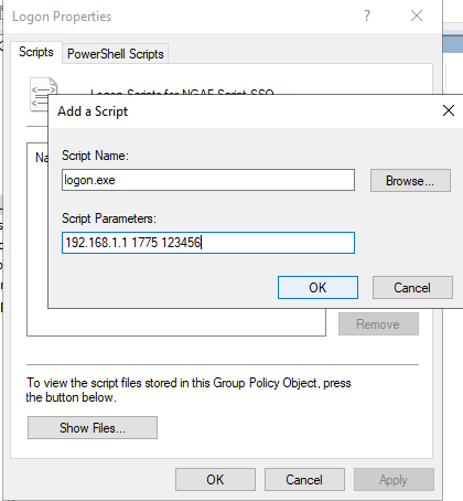
h) Configure the logout script program on LDAP. The user uses the logout script to log out of the device and log out of the domain.
i) Follow the above steps to configure the login script program, and double-click Logoff in Step f.
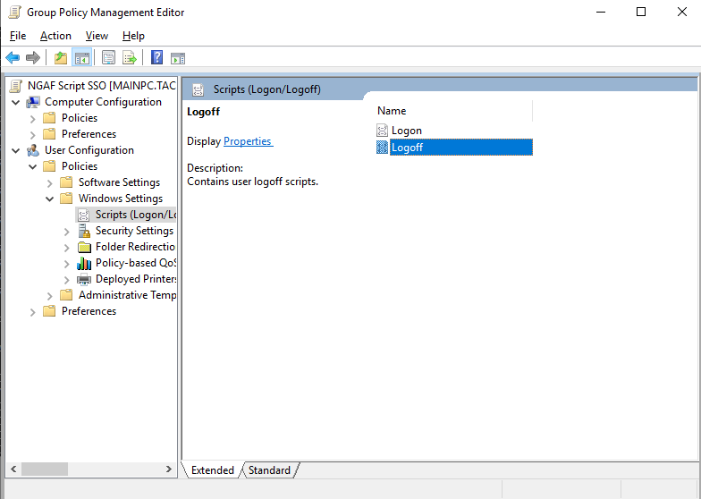
j) Click Show Files on the lower left of the Logoff Properties page. A directory will be opened. Save the logout script (i.e., logff.exe) file to this directory and then close the directory.
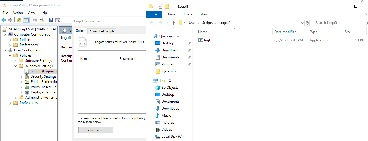
k) Click Add in the logout script editing window. In the Add a Script dialog box, click Browse, and select the saved AD logout script file (i.e., logff.exe). For Script Parameters, enter the IP address of Network Secure used in the login script configuration, and then close all the group policy property pages.
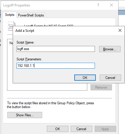
l) After configuring the scripts, click Start in the lower left of the desktop, and click Run. Enter "gpupdate" in the pop-up running window, and click OK to activate the configured group policy.
-
Go to Policies > Authentication > User Authentication > Authentication Policy, click Add. Set the authentication policy according to the IP or MAC address of the SSO user.
-
Log in to the domain on a PC. You can access the Internet after successful login.
a) Set the primary DNS of the user’s PC to the IP address of the domain server. Otherwise, the IP address of the domain cannot be parsed and you may fail to log in to the domain server.
b) If the DNS or IP address has been modified after successful user login to the domain for the first time, the user still can log in to the domain and access Windows with the correct password. However, the user has not logged in to the domain and the SSO is invalid. When the user attempts to access the network, an authentication box will pop up, asking the user to enter the username and password. The reason is that Windows can remember the correct password entered last time and the user can log in to the Windows system without logging in to the domain.
c) The domain server IP address, the device IP address, and the user’s PC shall be able to communicate with each other.
d) The Network Secure device communicates with the server over port 1775.
Configuration of AD SSO:
Login information can be automatically obtained through the built-in program of the Network Secure device. The Network Secure device has a built-in SSO client program named AD SSO. When this method is enabled, the program regularly obtains successful login information of PC logging into the domain and reports the information to the Network Secure device for SSO.
The Single sign-on configuration required to select AD SSO and select Enable AD SSO.
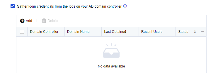
Click Add to add a domain server.
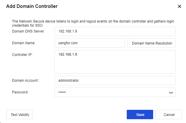
Domain DNS Server: Enter the Domain DNS Server and Domain Name. The Domain DNS Server shall be able to resolve the Domain Name. If you click the Domain Name Resolution button, it can automatically resolve the IP addresses of all domain controllers.
Domain Name: Enter the domain name of the domain server.
Controller IP: Enter the IP address of the domain server.
Domain Account: Enter the account (an administrator account or an account listed in the administrator group) with domain admin privileges.
Password: Enter the password of the Domain Account.
Click Test Validity to obtain the result of the domain controller test.
Click Save to save the configuration.
Redirection Interval After Auth Failure (mins): Set the time interval for redirection and re-authentication after IWA SSO fails.
Domain of Windows 2000 Earlier Versions: If the domain server runs on Windows earlier than 2000, you need to set the domain name here.
Notice:
- If the domain account expires or is disabled, the logged-in PC can still be successfully authenticated through Kerberos and display UI optimization.
- IWA authentication does not apply to mobile phone network access via proxy. If IWA authentication is enabled, the authentication window will not pop up as long as the proxy is working.
- Kerberos authentication will not kick out password-authenticated users.
- If a domain account contains special characters such as `~! #$%^&;*+|{};:“”‘’,/<>? attempts to log in, no authentication will be performed for this user (only for Network Secure).
Configuration of Listening Mode
In the listening mode, SSO is realized by listening to the data of the domain server that the PC logs in and obtaining user login information from the data. In this case, no components need to be installed on the domain server. However, the PC login data to the domain must be mirrored to the device through the device or listening port. The device listens to the login information of the UDP 88 port. The user successfully logged in to the domain can access the Internet directly without passing the device authentication again. This mode applies to domain servers on the LAN or WAN. The following describes SSO settings in two scenarios.
Scenario 1: Domain servers in the LAN environment
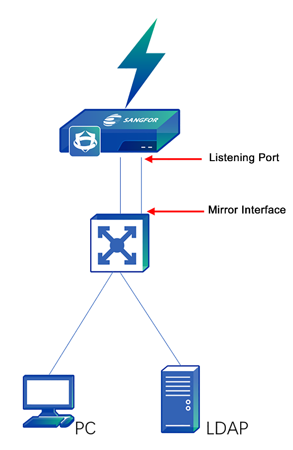
The data stream is as follows:
-
Network Secure monitors the whole process of computer logging into the domain.
-
If the login succeeds, the user is considered as having passed authentication.
Configuration Steps
-
Click Policies > Authentication > User Authentication > External Auth Server to set the authentication AD domain service.
-
Enable SSO on the device, select the listening mode, and set the IP address of the domain server. Click Policies > Authentication > User Authentication > Authentication Options > SSO Options > AD SSO for configuration. Tick the option Enable AD SSO to enable the domain single sign-on function.
-
Select Gather login credentials by monitoring the data when a device logs in to the domain to enable the listening mode for SSO. Enter the IP address and listening port of the domain server in the list of Monitored Domain Controllers. If there are multiple domain servers, specify one IP address and one port per row, as shown below.
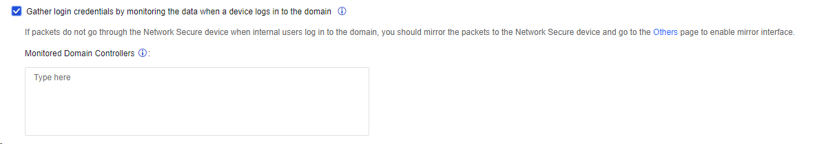
- If the login data does not pass through the device, you must go to the Others tab to enable the mirror interface and connect it to the switch’s mirror interface that forwards it. A mirroring interface must be an idle network interface.

-
Go to Policies > Authentication > User Authentication > Authentication Policy and click Add to set the authentication policy according to the IP or MAC address of the SSO user.
-
Log in to the domain on a PC. Then you can access the Internet.
Scenario 2: Domain servers on the WAN interface side
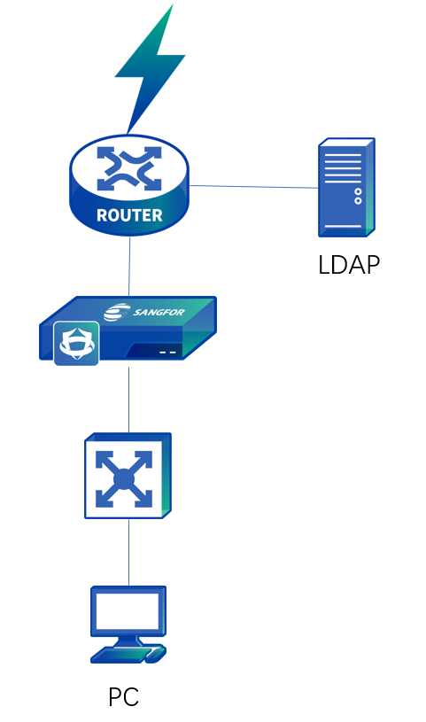
The data stream is as follows:
-
The PC logs in to the penetrable device of the domain.
-
The LAN port of the device also serves as the listening port, so you do not need to set another listening port.
Configuration Steps
-
Click Policies > Authentication > User Authentication > External Auth Server to set the authentication AD domain service.
-
Enable SSO on the device, select the listening mode and set the IP address of the domain server. Click Policies > Authentication > User Authentication > Authentication Options > SSO Options > AD SSO for configuration.
Select Enable AD SSO.
Select Gather login credentials by monitoring the data when a device logs in to the domain to enable the listening mode for SSO. Enter the IP address and listening port of the domain server in the list of Monitored Domain Controllers. If there are multiple domain servers, specify one IP address and one port per row, as shown below.

-
Go to Policies > Authentication > User Authentication > Authentication Policy and click Add to set the authentication policy according to the IP or MAC address of the SSO user.
-
Log in to the domain on a PC. You can access the Internet after successful login.
Notice:
In the mirror mode, only the login information of a user is monitored. If a user logs out, no data can be monitored. Therefore, there may be the case that the user who has logged out of a PC is still displayed in the online user list of the device.
Proxy SSO
It is applicable to network access via proxy. In this mode, each user is assigned an account of the proxy server. In proxy SSO authentication mode, when the user passes the proxy server’s authentication, it is also considered having passed the device’s authentication. Proxy SSO is realized in the listening mode, i.e., by listening to the login data.
WAN: The proxy server is on the WAN side, as shown below:
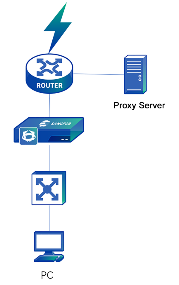
The data stream is as follows:
-
The user accesses the Internet through the proxy server, and the device monitors the interaction between the PC and the proxy server.
-
If the PC successfully passes the proxy server authentication, it is considered to have passed the device’s authentication.
Configuration Steps
- Enable SSO on the device, select the listening mode, and set the IP address of the domain server. Click Policies > Authentication > User Authentication > Authentication Options > SSO Options > Proxy SSO for configuration.
Select Enable Proxy SSO (if login packet to domain does not go through this device).
Enter the IP address and the listening port of the proxy server in Proxy Servers. If there are multiple proxy servers, specify one IP address and one port per row, as shown below. As to the listening port, set it to the proxy authentication port in this example.
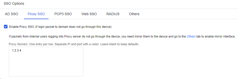
- If the login data does not pass through the device, you must go to the Others tab to enable the mirror interface and connect it to the switch’s mirror interface that forwards it. A mirroring interface must be an idle network interface.

-
Go to Policies > Authentication > User Authentication > Authentication Policy and click Add to set the authentication policy according to the IP or MAC address of the proxy SSO user.
-
Log in to the proxy server on a PC. You can access the Internet after successful login.
To enable automatic authentication for a proxy server on the WAN, enable access to the proxy server in the root group. Navigate to Policies > Authentication > User Authentication > Authentication Options > Others and select Basic services (except HTTP/HTTPS) are available before a user passes authentication. See the figure below.
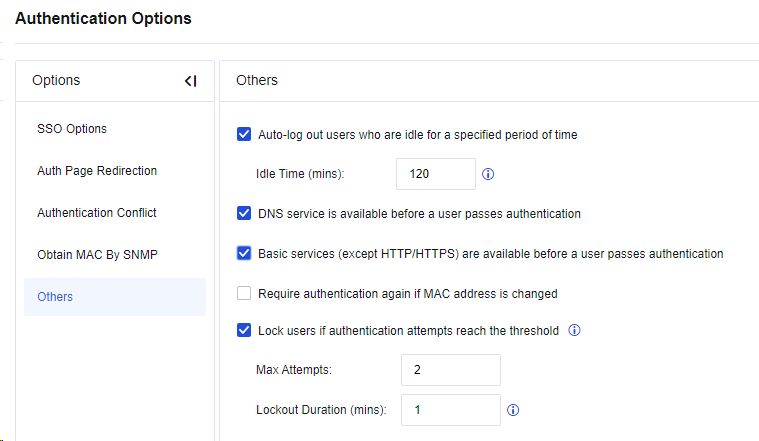
POP3 SSO
In an enterprise network with a mail server presence, user information is stored on the POP3 server. Suppose the user has logged in to the POP3 server and received or sent an email using Outlook or Foxmail before network access. In that case, the device obtains the login information in the listening mode and automatically identifies and authenticates the user as valid. At this time, the user accesses the Internet directly without the need to enter the username and password. This function applies to POP3 servers on both LAN and WAN. The following describes POP3 SSO settings in two scenarios.
Scenario 1: POP3 servers on the LAN
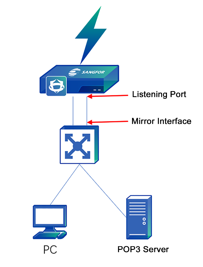
The data stream is as follows:
-
The user communicates with the POP3 server through the mail client, and the device listens to the whole process.
-
After the mail client successfully logs in to the POP3 server, the device automatically authenticates the user as valid, allowing the user to access the Internet without password verification.
-
As data is exchanged on the LAN, and the login data does not pass through the device, you need to set a listening port on the device.
Configuration Steps
-
Click Policies > Authentication > User Authentication > External Auth Server to set the authentication POP3 server.
-
Enable SSO on the device, select the listening mode, and set the IP address of the POP3 server. Click Policies > Authentication > User Authentication > Authentication Options > SSO Options > POP3 SSO for configuration.
-
Select Enable POP3 SSO. Enter the IP address and listening port of the POP3 server in Mail Servers. If there are multiple POP3 servers, enter one IP address and one port per row. In this example, the port here shall be set to the POP3 authenticated port (TCP110 by default).
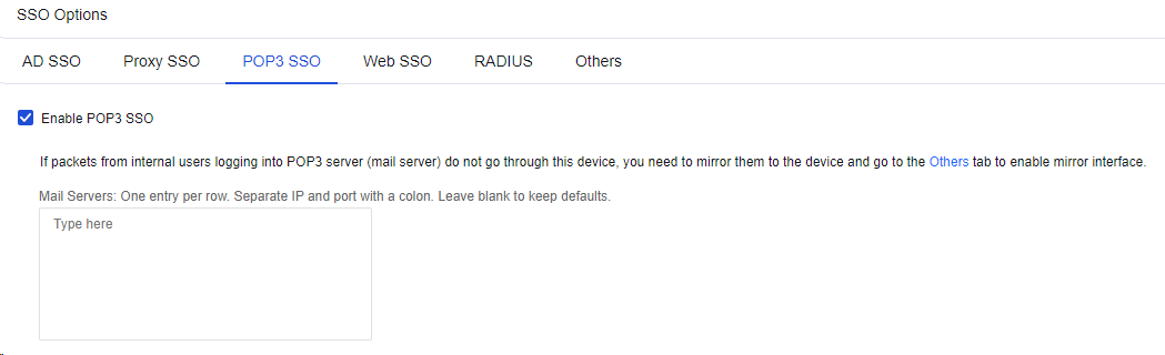
- If the login data does not pass through the device, you need to go to the Others tab to enable the mirror interface and connect it to the switch’s mirror interface that forwards login data. A mirroring interface must be an idle network interface.

-
Go to Policies > Authentication > User Authentication > Authentication Policy and click Add to set the authentication policy according to the IP or MAC address of the POP3 SSO user.
-
Send and receive emails once through the email client on the PC. Then, you can access the Internet after successfully logging in to the POP3 server.
Scenario 2: POP3 server on the WAN
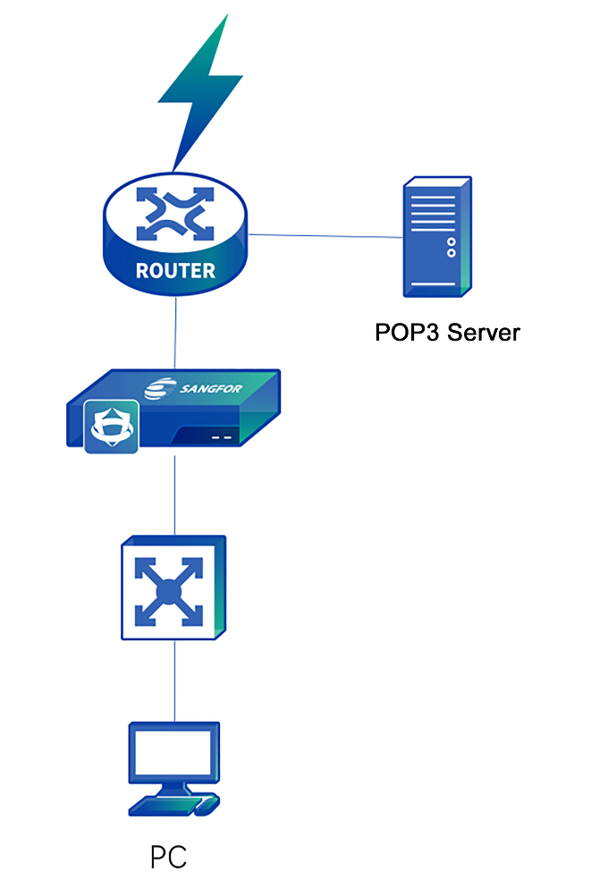
The data stream is as follows:
-
The PC logs in to the POP3 server through the device.
-
The LAN port of the device also serves as the listening port, so you do not need to set another listening port.
Configuration Steps
-
Click Policies > Authentication > User Authentication > External Auth Server to set the authentication POP3 server.
-
Enable SSO on the device, select the listening mode, and set the IP address of the POP3 server. Click Policies > Authentication > User Authentication > Authentication Options > SSO Options > POP3 SSO for configuration.
Select Enable POP3 SSO.
Enter the IP address and listening port of the POP3 server in Mail Servers. If there are multiple POP3 servers, enter one IP address and one port per row. In this example, the port shall be set to the POP3 authenticated port (TCP110 by default), as shown below.

-
Go to Policies > Authentication > User Authentication > Authentication Policy and click Add to set the authentication policy according to the IP or MAC address of the POP3 SSO user.
-
Send and receive emails once through the email client on the PC. Then, you can access the Internet after successfully logging in to the POP3 server.
To enable automatic authentication for the POP3 server on the WAN, enable access to the POP3 server in the root group. Navigate to Policies > Authentication > User Authentication > Authentication Options > Others and select Basic services (except HTTP/HTTPS) are available before a user passes authentication. See the figure below.

Web SSO
Web SSO applies to users whose account information is stored on their web servers. To implement Web SSO, the user needs to pass the authentication of the web server and the device before network access. It applies to Web servers on the LAN or WAN.
Scenario 1: Web server on the LAN

The data stream is as follows:
-
User login to the Web server is in plaintext, which is monitored by the device.
-
Whether Web SSO succeeds depends on the authentication result indicated by the keyword returned by the server.
Configuration Steps
- Enable Web SSO on the device, select the SSO mode. Navigate to Policies > Authentication > User Authentication > Authentication Options. Then, select SSO Options > Web SSO to go to the Web SSO configuration page. Select Enable Web SSO.

-
Enter the address of the Web authentication server in Web Authentication Server.
-
Select Redirect browser to the above server before authentication. Before authentication, the user will be redirected to this page for Web SSO upon webpage access.
-
Fill in User Form Name with the name of the table where "username" field locates for Web authentication.
-
Select Authentication success keyword or Authentication failure keyword to specify the keyword for identifying whether a Web login is successful. For example, if Authentication success keyword is selected, Web SSO is successful when the success keywords are included in the result returned by POST. If Authentication failure keyword is selected, Web SSO failed when the failure keywords are included in the result returned by POST.
-
Click the Others tab, select Enable mirror interface, and specify the listening port.
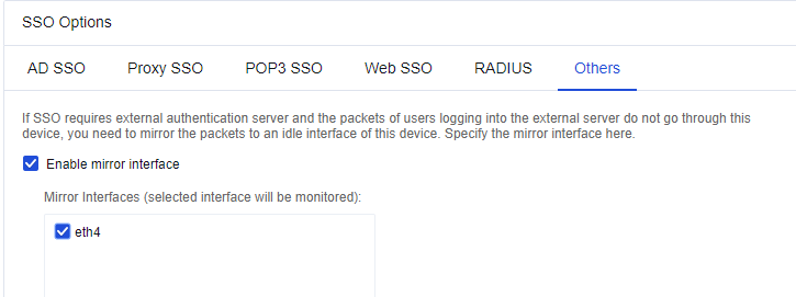
- Log in to the website set on the PC, such as the BBS in this example. You can access the Internet after a successful login.
Scenario 2: Web server on the WAN
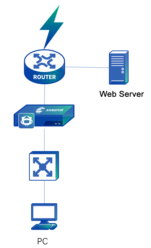
The data stream is as follows:
-
The PC logs in to the Web server through the device.
-
The LAN interface of the device also serves as the listening port, so you do not need to set another listening port. After successful login to the Web, the Web SSO is successful.
Configuration Steps
- Enable Web SSO on the device, select the SSO mode. Navigate to Policies > Authentication > User Authentication > Authentication Options. Then, select SSO Options > Web SSO to go to the Web SSO configuration page. Select Enable Web SSO.
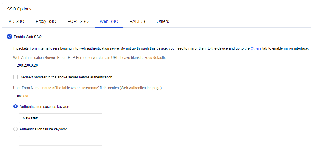
-
Enter the address of the Web authentication server in Web Authentication Server.
-
Select Redirect browser to the above server before authentication. Before authentication, the user will be redirected to this page for Web SSO upon webpage access.
-
Fill in User Form Name with the name of the table where "username" field locates for Web authentication.
-
Select Authentication success keyword or Authentication failure keyword to specify the keyword for identifying whether a Web login is successful. For example, if Authentication success keyword is selected, Web SSO is successful when the success keywords are included in the result returned by POST; if Authentication failure keyword is selected, Web SSO failed when the failure keywords are included in the result returned by POST.
-
Log in to the website set on the PC, such as the BBS in this example. You can access the Internet after successful login.
RADIUS SSO
When there is any RADIUS server in the user environment, and the data packets used for authentication and billing via the RADIUS server pass through the Network Secure device, you can enable RADIUS SSO. After successful authentication, the RADIUS username can be used to log in to the Network Secure device.
Select Enable RADIUS SSO, and enter the address of the RADIUS server in RADIUS server IP addresses.
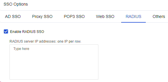
Suppose RADIUS authentication and billing packets do not pass through the Network Secure device. In that case, you need to set a mirror interface on the Network Secure device to mirror the data to the Network Secure device.

Others
Others: If server login data does not pass through the gateway, you need to select an idle interface to monitor the login data as a mirror interface. Such an interface is required in AD SSO, POP3 SSO, Proxy SSO, and Web SSO.

Auth Page Redirection
Auth Page Redirection: Specify the page to which the web browser will be redirected after a user passes authentication.
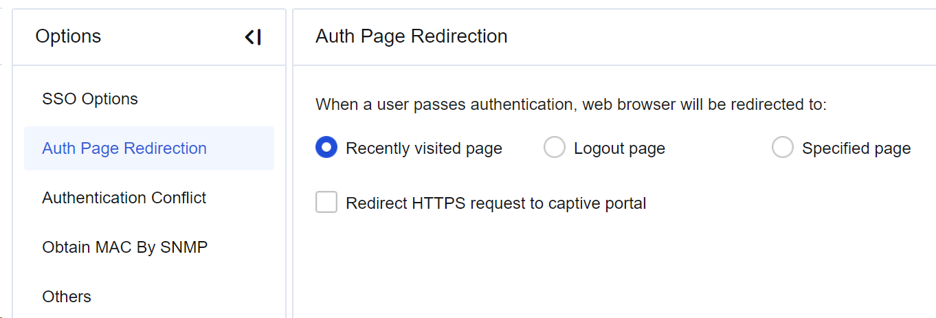
Recently visited page: If this option is selected, the user is redirected to the page visited before authentication.
Logout page: If this option is selected, the user is redirected to the logout page.
Specified page: If this option is selected, the user is redirected to a specified page.
Redirect HTTPS request to captive portal: If this option is selected, the HTTPS access request sent before authentication will be redirected to the authentication page.
Authentication Conflict
Authentication Conflict: Specify how to process repeated logins of accounts that disallow concurrent logins. If repeated login is detected, the device either Terminate previous session and require authentication with the current IP or Only tell the user that another user is already logged into this account somewhere else. See the figure below.
Obtain MAC By SNMP
When LAN users are authenticated by binding or limiting the MAC address in layer 3 LAN, Obtain MAC by SNMP must be enabled to obtain the MAC addresses of LAN users. To access this function, the switch on the LAN must support the SNMP.
Principle: The Network Secure device sends SNMP requests to the layer 3 switch regularly to obtain the MAC address table of the switch and stores the table in the device’s memory. Assume that a computer with the MAC address from another network segment of the layer 3 switch (different from the network segment of the LAN port of the device), for example, 192.168.1.2, accesses the Internet through the device. When the computer packets pass through the device, the device detects that the MAC address of the packets is a layer 3 one. Instead of processing the MAC, the device looks for the real MAC in its memory by using the IP address 192.168.1.2 to authenticate the real MAC of the user.
Configuration Steps
-
Enable SNMP on the layer 3 switch.
-
Navigate to Policies > Authentication > User Authentication > Authentication Options > Obtain MAC by SNMP and select Enable SNMP Settings.
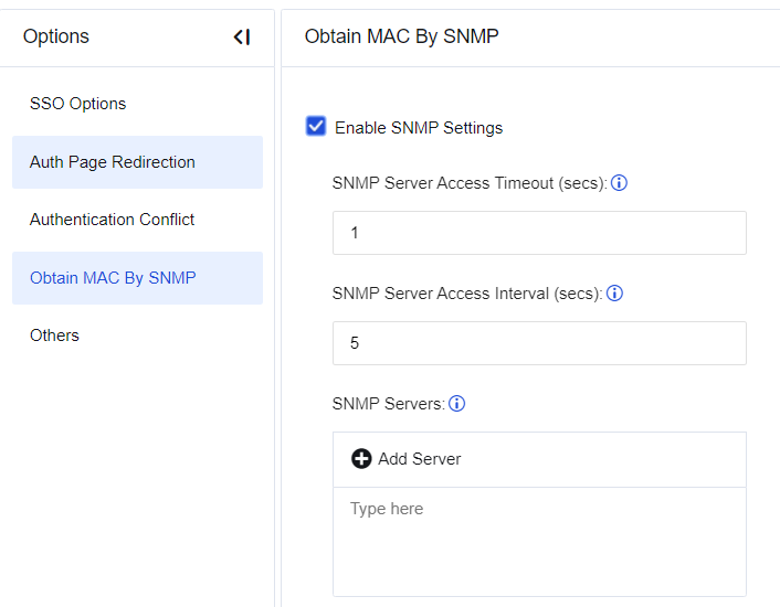
-
Specify SNMP Server Access Timeout (secs) and SNMP Server Access Interval (secs), which are generally set to default values.
-
In SNMP Servers, click Add Server. In the Add SNMP Server dialog box, specify SNMP Server IP Address and click Search. Select the target server returned below and click Save. See the figure below.
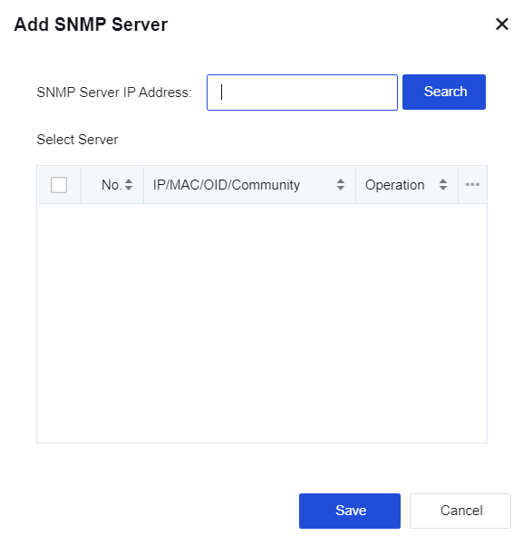
-
Go to Policies > Authentication > User Authentication > Authentication Policy. Set the authentication policy according to the IP or MAC address of the verified user.
-
PCs under the layer 3 switch can now directly access the Internet after being authenticated as new users.
To search for the SNMP server by IP address, SNMP must be enabled on this server, and Community is set to public. Otherwise, the search will fail, and you must manually set the SNMP server.
Others
To configure the options related to authentication, as shown in the figure below.
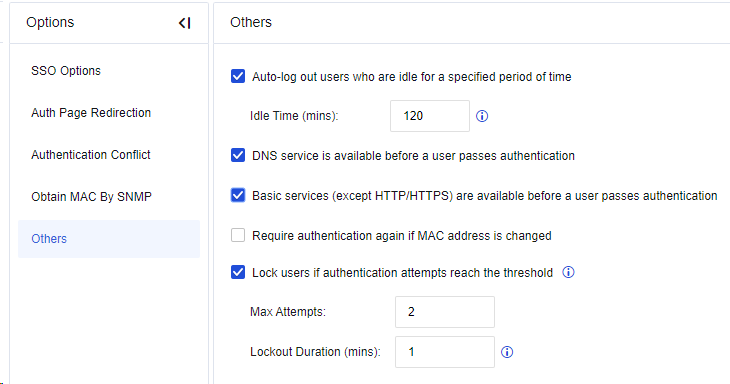
-
Auto-log out users who are idle for a specified period of time: You can set an idle period beyond which users are logged out automatically.
-
DNS service is available before a user passes authentication: If this option is selected, the user can access the DNS service before authentication.
-
Basic services (except HTTP/HTTPS) are available before a user passes authentication: If this option is selected, the user can use root group permissions except for HTTP and HTTPS services before authentication.
-
Require authentication again if MAC address is changed: If this option is selected, the user who has passed the authentication will need re-authentication when the MAC address is changed. Assume that a user whose IP address is 192.168.1.1 has been authenticated by username and password. If the user goes offline and another user changes the IP address to 192.168.1.1 before this user is logged out, the MAC address will change accordingly. In this way, this user must be re-authenticated before network access.
-
Lock users if authentication attempts reach the threshold: To specify the maximum attempts and lockout duration (mins) for authentication.
External Authentication Server
In External Authentication Server, third-party authentication servers can be configured, including LDAP, RADIUS, and POP3.
LDAP Server
On the Policies > Authentication > User Authentication > External Auth Server page, click Add and select LDAP Server. On the Add LDAP Server dialog box, enter the name of the server.
In Basics Settings, fill in the server’s IP address, authentication port, timeout, and Base DN (the specific path of the server where the user locates).
Basic Settings:
IP Address: Enter the address of the LDAP server docking AC.
Port: Port connecting to the LDAP server. For example, if the AD domain does not enable SSL/TLS encryption, the port is 389 by default.
Timeout (secs): Set the timeout for an authentication request. If no response is given in this period after the AC device forwards an authentication request to the LDAP server, it is deemed as an authentication failure. If the network between the Network Secure device and the LDAP server is slow, you can prolong the timeout period (e.g., 10 seconds).
Base DN: Specify the start point of the domain search path, which determines the effective range of the LDAP rule. If the user is outside the specified BaseDN, external server authentication does not apply, and the policy configured is invalid for the user. Therefore, Base DN can be used to divide the regions of administrators.
Sync Options:
Type: MS Active Directory, Open LDAP, SUN LDAP, IBM LDAP, OTHER LDAP.
Anonymous Search: Available if the LDAP server supports anonymous search.
Admin DN: The Network Secure device uses this account to access the LDAP server to search for and synchronize LAN user accounts.
Password: Password corresponding to the domain user.
User/Group Attribute: Specify the unique user attribute field on the LDAP server. For example, the user identifier "sAMAccountName" attribute is on the AD domain, and the UID is on Novell LDAP.
Group: Specify the user filter conditions of the LDAP server, which determines whether a node is a user. For example, "(|(objectClass=user)(objectClass=person))" can be used in the AD domain to determine if a node is a user.
Search Settings:
Paged Search: Search the LDAP server with the extended API. It is suggested that the default configuration be retained.
Page Size: The size returned upon LDAP paging. 0 indicates unlimited size. It is suggested that the default configuration be retained.
Size limit: This option is provided for LDAP synchronization. In this example, it is suggested that the default configuration be retained.
RADIUS Server
On the Policies > Authentication > User Authentication > External Auth Server page, click Add and select RADIUS Server. In the Add RADIUS Server dialog box, enter the name of the server.

Name: Set the name of the Radius server.
IP Address: Fill in the IP address of the RADIUS server.
Port: Set the authentication port of the Radius server, which is 1812 by default.
Timeout (secs): Set the timeout for an authentication request.
Shared Key: Set the agreed key of the Radius server.
Protocol: Set Radius negotiation protocol, options including Non-encrypted protocol PAP, Challenge handshake authentication protocol, Microsoft CHAP, Microsoft CHAP2, and EAP_MD5.
POP3 Server
On the Policies > Authentication > User Authentication > External Auth Server page, click Add and select the POP3 Server. In the Add POP3 Server dialog box, enter the name of the server.

POP3 server configuration:
IP Address: Enter the IP address of the POP3 server.
Port: Enter the serial number of the authentication port.
Timeout (secs): Set the timeout for an authentication request.
Custom Webpage
To customize the page that the device redirects to a terminal. Supported options are authentication result page, access prohibition page, virus discovery page, password change page, announcement file, Web authentication page, and user locking message page.
Enable: It is recommended to enable this option. Otherwise, the page will not be displayed.
Note:
You cannot disable the Malicious Access, Antivirus Notification, Authentication Successful, and Web-Based Login Portal pages.
Page Contents: The page displayed is modified by changing its source codes. You are advised to modify only the texts and pictures because other modifications will result in link loss.
Click Preview to preview the current custom page; click Save to save the page; click Restore Defaults to restore the device’s original page; click Restore Previous Edition to restore to the last customization page.

Objects
Objects are defined to provide basic settings to ensure device safety. Specifically, vulnerability attack prevention, web app protection, botnet, and LAN security are referenced using objects. The object definition defines application content signature database, security protection signature database, IP address database, schedule, network objects, service, trusted certificate authority, etc.
| Module | Description |
|---|---|
| Network Objects | Used to set IP address or IP address group to facilitate reference of the application control and security protection policies. |
| Link State Detection | Used to detect the effectiveness of WAN links. |
| Services | By specifying the ports and protocols, the user can configure services. Port and protocol configuration of data packets allows data control. |
| Security Policy Template | The user can define the content of a security template, which is referenced by security policies. Security policy templates include vulnerability attack prevention, Web application protection, Bonet, and content security. |
| Threat Signature Database | The user can look up security rules or customize rules. These rules are collected as a reference for security templates. |
| Content Identification Database | It can be used to recognize traffic content, including applications, URLs, and files. It is referenced by securities templates. |
| SLB Server Pools | You can add an SLB server pool as the destination IP address for destination NAT or bidirectional NAT. An IP address is selected from the server pool as the destination IP address for NAT based on the weighted round-robin algorithm, ensuring balanced traffic distribution across servers. |
| IP Location Database | It is used to import ISP address segments or change IP locations, providing a routing reference. |
| Schedule | It is used to set a schedule. Most control operations on the device can be performed based on the time segment. This object allows the user to set a time range to facilitate use in the control policy. |
Table 20: Objects Function Description
Network Objects
To define IP address sets, which can be LAN IP addresses, or an IP range, or all IP addresses in the public network. These sets can form a new set, namely the IP address group. Network objects properly defined provide calls such as application control policy. The objects can be imported or exported to perform quick configuration, as shown below.
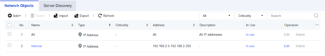
Click Add to add network objects according to the address or address group. There are three types of addresses: IP Address, Business Asset Address, and User IP Address. See the figure below.
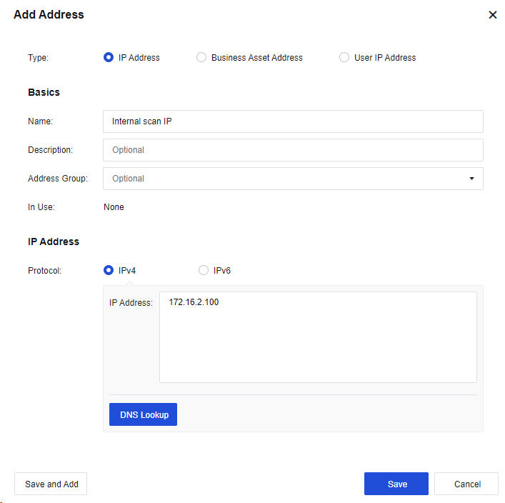
Name: Fill in the corresponding name.
Description: Enter description information.
Address Group: (Optional) The group to be joined by the IP address.
Protocol: Select IPv4 or IPv6.
IP Address: Enter the IP address.
DNS Lookup: To resolve the relationship between the domain name and the IP address, after which the corresponding IP address will be entered into the IP address box.
Note:
The DNS lookup function works through the device. Therefore, the device must be able to access the Internet and configure a valid DNS address to resolve the domain name.
In the figure below, the Business Asset Address is selected.
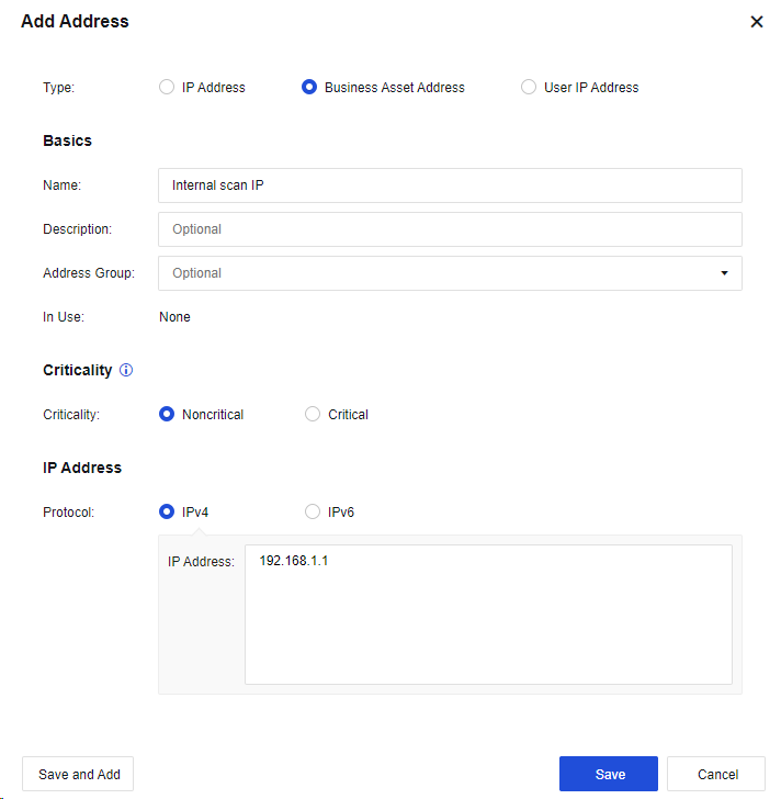
Criticality: Mark the criticality of a business asset to prioritize or manage its security issue.
In the figure below, the User IP Address is selected.
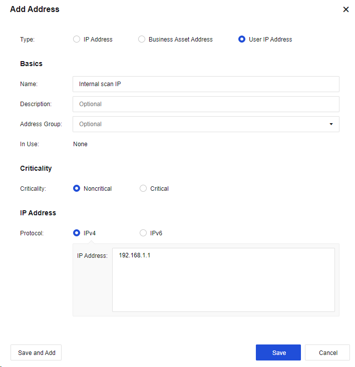
Criticality: There are Noncritical and Critical users. You can select either of them as required.
On the Network Objects tab, click Add and select Domain Name. See the figure below.
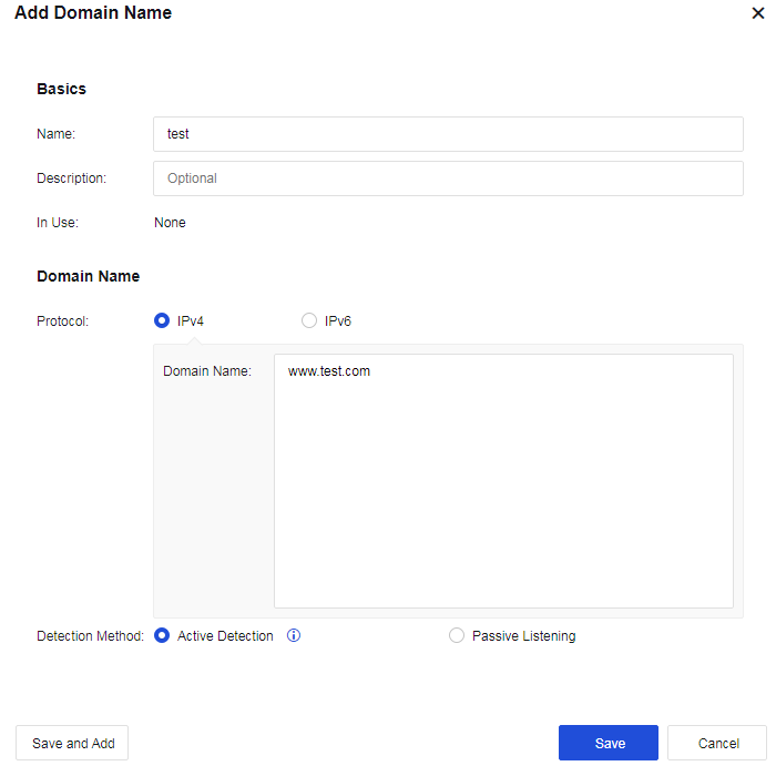
Protocol: Select IPv4 or IPv6.
Detection Method: When Active Detection is selected, the device initiates a DNS resolution request to obtain the IP address of the domain name. When Passive Listening is selected, the device analyzes the DNS packets passing through it to obtain the IP address of the domain name.
On the Network Objects tab, click Add and select Address Group. See the figure below.
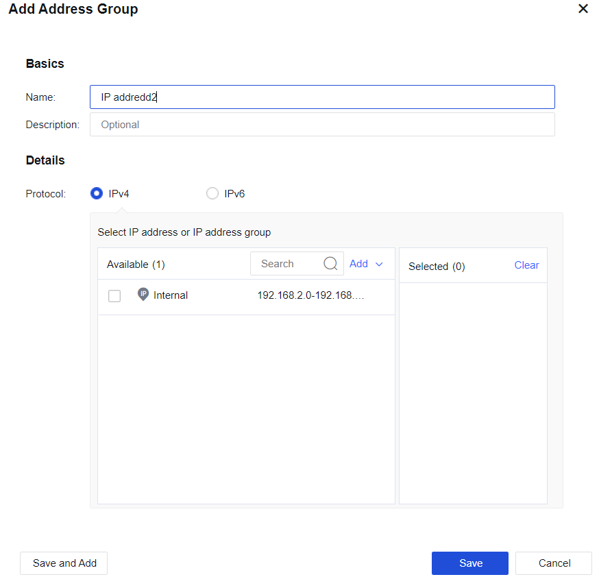
Protocol: IP groups in an address group must be of the same IP type (IPv4 or IPv6).
Select IP address or IP address group: Select the IP address or IP address group to be contained in the address group as required.
Server Discovery
Discovered server information will be displayed on this tab, including open ports and page number of sensitive data. See the figure below.
Add To: Select business assets to be added.
Ignore: Ignore the server information that is discovered.
Ignored Servers: View ignored servers.
Advanced: Whether to enable server discovery and whether to discover data business.
Link State Detection
Link State Detection is used to detect the effectiveness of WAN links. In scenarios involving multiple WAN links, traffic automatically switches to other normal links if one of the links fails. Detection methods include ARP Probe, DNS Lookup, PING, and BFD. As shown in the figure below.
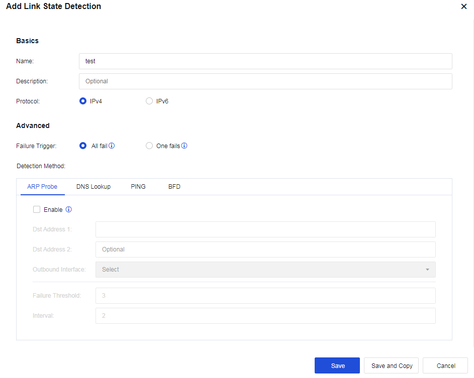
Failure Trigger: You can select All fail or One fails. When All fail is selected, the link is considered down if the results of all detection methods show the link failed. When One fails is selected, the link is considered down if one detection method shows the link failed.
ARP Probe: Detect the link state by sending ARP packets to the specified network devices in a group. Each group can contain two destination IP addresses at most, and the two IP addresses must be separated by a comma.
DNS Lookup: Detect the link state by sending DNS resolution requests to the specified DNS servers. You can configure two groups of DNS servers at most. The link will be considered failed if either group fails to resolve the domain name.
PING: Detect the link state by pinging the specified servers. You can configure two groups of destination IP addresses at most. Each group can contain two destination IP addresses at most, and the two IP addresses must be separated by a comma. The link will be considered failed if all IP addresses in either group fail to respond to the ping request.
BFD: As BFD is based on RFC 5880, BFD sessions at both peers are required to establish a detection system. Link state is detected by using UDP port 3784 to identify BFD control packets and UDP port 3785 to identify BFD echo packets.
Services
A combination of specific protocols and ports, service usually represents a particular network application. It can be called by an application control policy to allow or deny certain network services. Service configuration is shown in the figure below.
Predefined Services: It defines the default ports of common protocols, which cannot be edited or modified. See the figure below.
Custom Services: When there is no suitable predefined service, you can manually customize services by clicking Add, as shown below.

Name: Fill in the corresponding name.
Description: Enter description information.
Protocol: Support TCP, UDP, ICMP, or other protocols. The specific port numbering can follow the corresponding protocol.
Service Groups: Combine several services into a group. To reference multiple services, you can directly reference the corresponding service group. Click Add to create a group, as shown below:
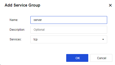
Name: Fill in the corresponding name.
Description: Enter description information.
Service: Select a service that needs to be defined.
Security Policy Template
To integrate multiple security rules into a template to facilitate calling by the security policy. You can modify the template to satisfy business requirements.
Intrusion Prevention
This function checks packets for latent threats against the LAN system. Two internal templates are configured, Internet access control and business protection:
-
Default Template_Internet Access Scenario is to protect LAN users.
-
Default Template_Server Scenario is to protect servers.

Click Add to create a vulnerability attack prevention template, as shown in the figure below.
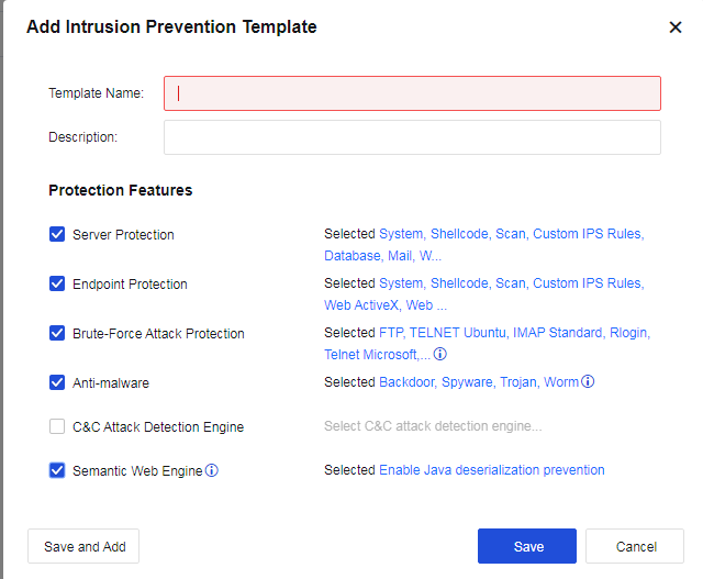
Template Name: Define the name of the template to prevent the attack behavior.
Description: Define the description of the template to prevent the attack behavior.
Protection Features: Specify the protection parameters.
Select Server Protection and click Selected System, Shellcode, Scan, Custom IPS Rules, Database, Mail, Web, FTP, TFTP, DNS, Telnet, IoT, Media. In the Select Attack Type dialog box, select vulnerability types according to the service type published by the server. The server will prevent attacks against vulnerabilities of this service type.
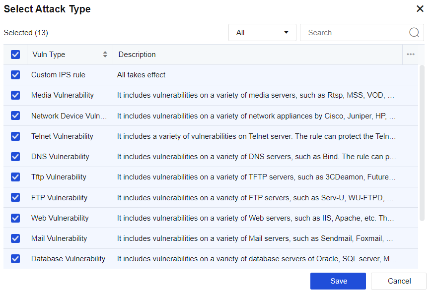
Check Endpoint Protection and click Selected System, Shellcode, Scan, Custom IPS Rules, Web ActiveX, Web Browser, File, Application. Then, the Select Attack Type dialog box will pop up, where you can check corresponding vulnerability types, and the server will perform intrusion prevention against the vulnerabilities related to this type of client.
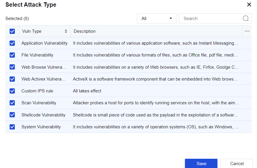
Select Brute-Force Attack Protection and click Selected TELNET_Ubuntu, IMAP_Standard, RLOGIN, TELNET_Microsoft_Server…. In the Select Attack Type dialog box, select vulnerability types. The server will prevent attacks against this type of brute-force attack.
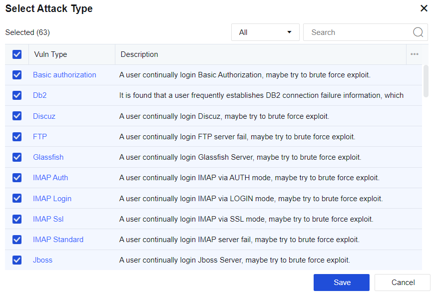
Click a brute-force attack to enter the Edit Signature dialog box (the vulnerability attack signature database) to set the maximum attacks allowed, detection interval, and status (Enable or Disable).
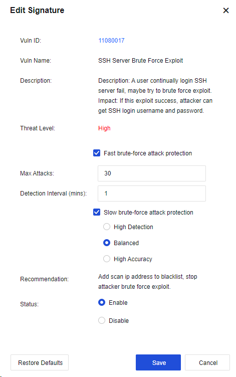
Check Anti-malware and meanwhile click Selected Backdoor, Spyware, Trojan, Worm. Then, the Select Attack Type dialog box will pop up, where you can check corresponding vulnerability types, and the server will perform intrusion prevention against this type of malware.
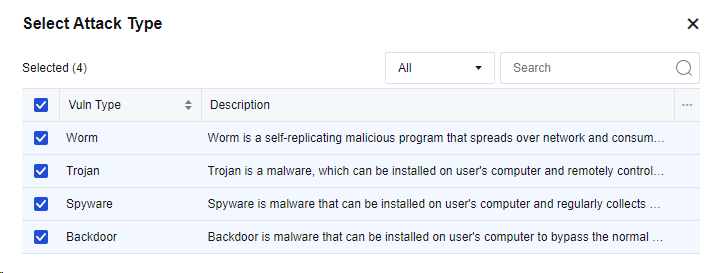
Check the option C&C Attack Detection Engine and click Select C&C attack detection engine. Then, the C&C Attack Detection Engine dialog box will pop up, where you can select corresponding detection engine, and the server will perform intrusion prevention against such C&C attacks.

Check Semantic Web Engine and click Selected Enable Java deserialization prevention. In the Semantic Web Engine dialog box, you can check Enable Java deserialization prevention for the server to prevent Java deserialization.
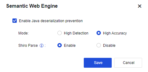
Click Save to finish establishing vulnerability attack protection.
On the Intrusion Prevention page, click Advanced to navigate to the advanced options configuration page. See the figure below.
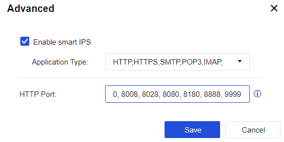
Select Enable smart IPS to identify vulnerability attacks and protect vulnerabilities based on applications. If this option is not selected, the system identifies IPS vulnerabilities based on ports.
HTTP port: Add multiple HTTP ports to identify HTTP attacks more accurately.
Web App Firewall
Web App Firewall is a set of protection policies to protect LAN Web servers from Web application attacks, including system command injections, SQL injections, and XSS attacks. It also allows configuration against data leakage of Web servers. See the figure below.
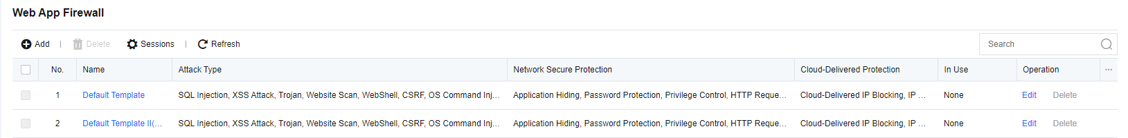
Default Template: Enable regular WEB protection (by default) and disable scanner block.
Default Template II (Scanner Blocker enabled for non-proxy access): Enable regular Web protection (by default) and Scanner Blocker.
Click Add to create a web app protection template, as shown in the figure below.
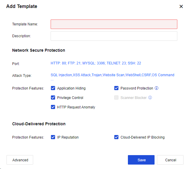
Template Name: Define the name of the template.
Description: Define the description of the template.
Network Secure Protection: Set up protection against server attacks.
Port: Specify the port of the protected server. This value is generally set to the server port. After setting, when the user accesses the server port, the system performs attack detection. For the HTTP port, you can also select Also protect HTTP access on other ports for auto-learning. See the figure below.
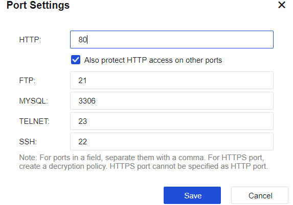
In Attack Type, click SQL Injection,XSS Attack,Trojan,Website Scan,WebShell,CSRF,OS Command. In the Select Attack Type dialog box, select attack types. The device will prevent attacks against this service type.

| Protection Type | Note |
|---|---|
| SQL Injection | By exploiting security vulnerabilities in design, attackers paste the SQL code to input boxes on web pages to obtain network resources or change data. |
| XSS Attack | Short for cross-site scripting (XSS), XSS is a computer security vulnerability frequently seen in Web apps. It allows attackers to implant code into pages provided to other users. In the HTML code and client script, attackers can exploit XSS vulnerabilities to bypass access control and intercept data like accounts. |
| Trojan | Trojan is an HTML web page wittily designed by hackers. When a user visits such a web page, the script embedded in it exploits the browser vulnerability to download and run the Trojan placed by the hacker on the browser. |
| Website Scan | The structure and vulnerabilities of a website are scanned. |
| WebShell | Also called the website backdoor Trojan, WebShell is a script tool for web intrusion and appears as an ASP, PHP, or JSP program page. After hacking a website, attackers usually place Trojans in the server’s Web directory and mix it with normal web pages. Via WebShell, hackers can control the victim’s website for a long time. |
| CSRF | Cross-Site Request Forgery is an attack that attackers exploit trusted websites by disguising requests from trusted users. |
| OS Command Injection | By exploiting server OS vulnerabilities, attackers transmit OS commands to the server via Web access to obtain network resources or change data. |
| File Inclusion | It is a malicious attack against PHP websites. When PHP variables are not strictly filtered and unknown whether the parameter is from a local or remote host, a file on the remote host may be specified as a parameter and submitted to the variable pointing. If the submitted file contains a malicious code or even a Trojan, the code or Trojan in the file will be successfully executed with the Web’s permission. |
| Path Traversal | Attackers access restricted directories outside the Web server’s root directory by adding "../" or variants to any directory of the Web server or special directories through a browser. |
| Information Disclosure | This vulnerability is caused by an incorrect Web server configuration or its security vulnerability. As a result, system files or configuration files are exposed to the Internet and sensitive information of the Web server is prone to leakage, including username, password, source code, server information, and configuration information. |
| Website vulnerabilities | It provides safe, reliable, and high-quality protection for specific vulnerabilities in well-known whole-site Web systems. |
| WebShell Backdoor | Having known a web system vulnerability, attackers may use it to implant a WebShell page into the Web system, and access the database through the WebShell page. In doing so, they can execute system commands to control the Web system for a long time. |
| Custom WAF Signature | The user can customize the protection rules for server protection in Custom Rules. |
Table 21: Description of Web App Protection Types
Protection features: The main functions are Application Hiding, Password Protection, Privilege Control, HTTP Request Anomaly, and Scanner Blocker. To enable advanced protection features, click Advanced for settings.
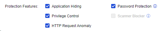
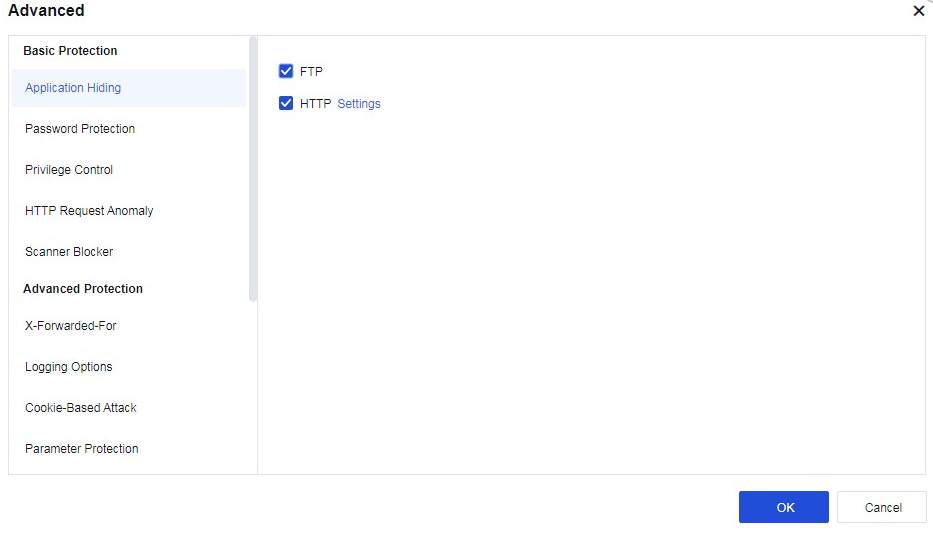
Application Hiding
FTP: When the client logs in to the FTP server, the server returns the version information of the FTP server to the client. Attackers can launch attacks by exploiting the vulnerabilities of corresponding versions. This function prevents attacks by hiding the version information returned by the FTP server. Select FTP to enable this function.
HTTP: When a client visits a website, the server will return many fields of the client in the HTTP header, such as Server, Via, etc. The version of the proxy server may be revealed by Via and may be exploited to launch attacks. Such attacks can be prevented by hiding these fields. Select HTTP and click Settings. Then, the following dialog box will appear.
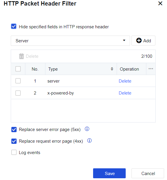
Enable Hide specified fields in HTTP response header and customize the content of the HTTP header. You can use HTTPWATCH or other packet capturing tools to capture some fields returned by the server to the client and enter them here. Select Replace server error page (5xx).
Error pages, like a page where the server returns error code 500 (server information included), will be replaced by the firewall with an error page that does not contain server information.
Password Protection
Password protection: This function applies to HTTP protocols. It mainly filters some oversimple usernames and passwords. Check Password Protection and click Advanced to display the page as follows.

Web-based login weak password detection: Enable it to protect the weak passwords in Web login. Click Settings to increase the complexity and add a custom password library, as shown below.
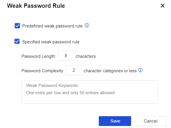
Select the predefined weak password rule or fill in the weak password list. Click Save to validate the settings. When such weak passwords are detected, the firewall will generate a log to remind the administrator.
Web-based cleartext detection: Enable it to detect plaintext transmission during Web login.
Web-based brute-force attack protection: It protects against Web password blasts. Click Settings to enter the setting page, as shown below.
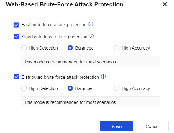
Fast brute-force attack protection: It utilizes the built-in WAF password attack protection rule to detect password blast behaviors in real-time.
Slow brute-force attack protection: The IP addresses of attacking sources with a low brute frequency that is hard to detect previously can now be detected by algorithmic analysis of offline logs within the specified time.
High Detection: Last for 15 minutes with 2 logins per minute; low threshold setting, easy to trigger brute-force attack, applicable to scenarios with the high-security requirement.
Balanced: Last for 21 minutes with 4 logins per minute; moderate threshold setting, applicable to brute-force attack detection in most scenarios, recommended setting.
High Accuracy: Last for 45 minutes with 8 logins per minute; high threshold setting, hard to trigger brute-force attack, applicable to scenarios with high business continuity requirements.
Distributed brute-force attack protection: When multiple devices attack a server, the IP address of the brute-force attack source that is hard to detect previously can now be detected by algorithmic analysis of offline logs within the specified time.
Web-Based Login Password Parameters: The custom password protection rules added on this page will be automatically synchronized to the Objects > Threat Signature Database > Custom Database. Click Add to create a custom Web password protection rule, as shown below.

Privilege Control
File Upload Restriction: Filter the types of files uploaded to the server from clients. Select File Upload Restriction and click Settings. The File Upload Restriction dialog box will pop up as follows.

Click the dropdown box next to Blacklist to select the built-in file types of the device. Click Add to add them to the list. To add a custom file type, enter it in the box and click Add to add it to the list.
URL Access: Control the permission switch. For example, if access to a URL is denied, no attacks will happen and therefore this URL is not subject to web app protection. If access to a URL is allowed, this URL is on the whitelist and is not subject to web app protection. Check URL Access and click Settings to enter the following page.
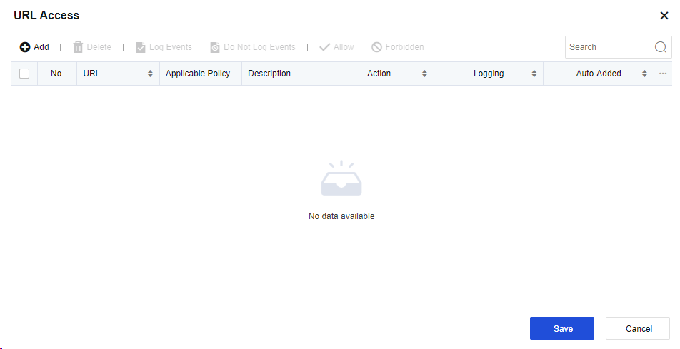
Click Add to add URL filter as shown below.
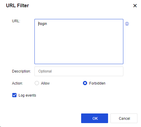
The parameter value is specified similarly to the anti-blasting rule: The URL suffix is required. For example, if a URL is http://www.***.com/login.html, enter "/login.html" and allow or deny access to the URL as required.
HTTP Request Anomaly
Filter request methods: HTTP is allowed, but after this function is enabled, HTTP requests will be disabled. Specifically, the selected HTTP request methods will be considered abnormal and blocked, as shown below.
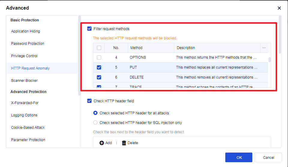
Check HTTP header field: The Referer, User-Agent, and Host fields in the HTTP header can be checked for SQL injection and other attacks.
Note:
To use this function, enable web protection "SQL Injection" in the Web app protection policy, as shown below.
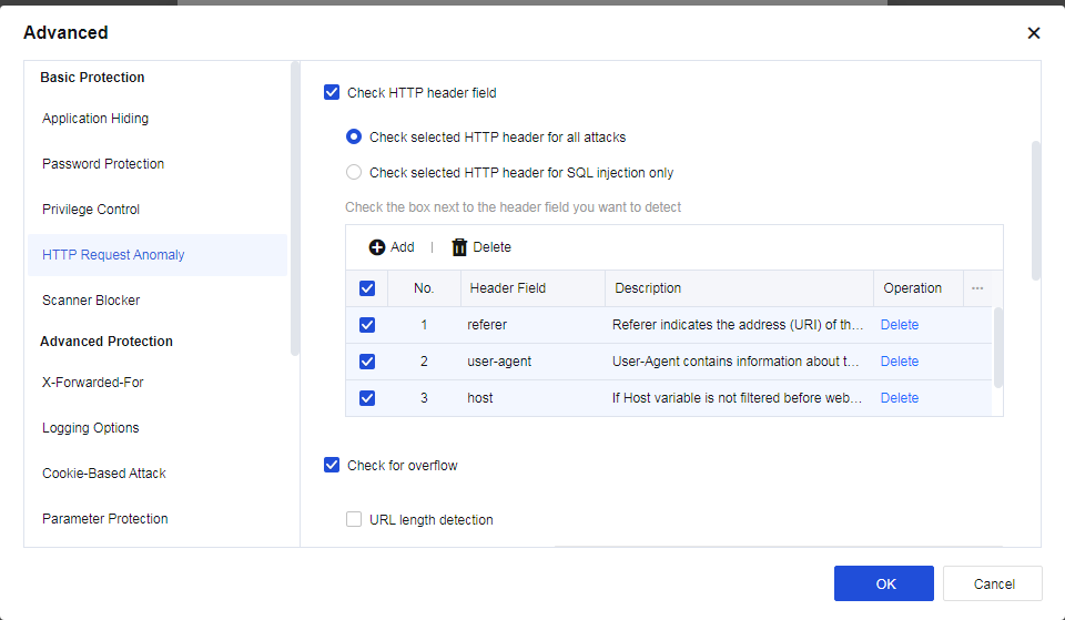
If the Host field is selected, when the system detects an SQL injection attack, and the attack type marked by the data center is still SQL injection, the Host field in the header of the HTTP packet will be intercepted.
Check for overflow: Overlong HTTP fields are prevented to avoid overflow, as shown below.
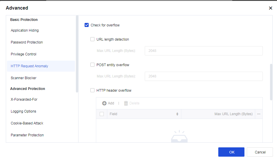
URL length detection: Select URL length detection and set the maximum length to prevent buffer overflow.
POST entity overflow: Select POST entity overflow and set the maximum length of the entity part of the POST data to prevent overflow of the data received by the server.
HTTP header overflow: Select HTTP header overflow and click Add to set the maximum length of the specified field in the HTTP header to detect excessive length.
Lock byte range: Select Lock byte range and set the number of allowed ranges to prevent the number of range fields from exceeding the allowed value.
Detect protocol anomalies: Protect ASP and ASPX pages from multi-parameter attacks caused by incorrect server processing when multiple parameters are requested. Meanwhile, the following items are enabled: Detect multipart header anomaly, Check whether Content-Type header field is repetitive, Detect chunk header anomaly in the request stream, Check whether charset header field in the request stream is repetitive, and Detect content-length header anomaly in the request stream.
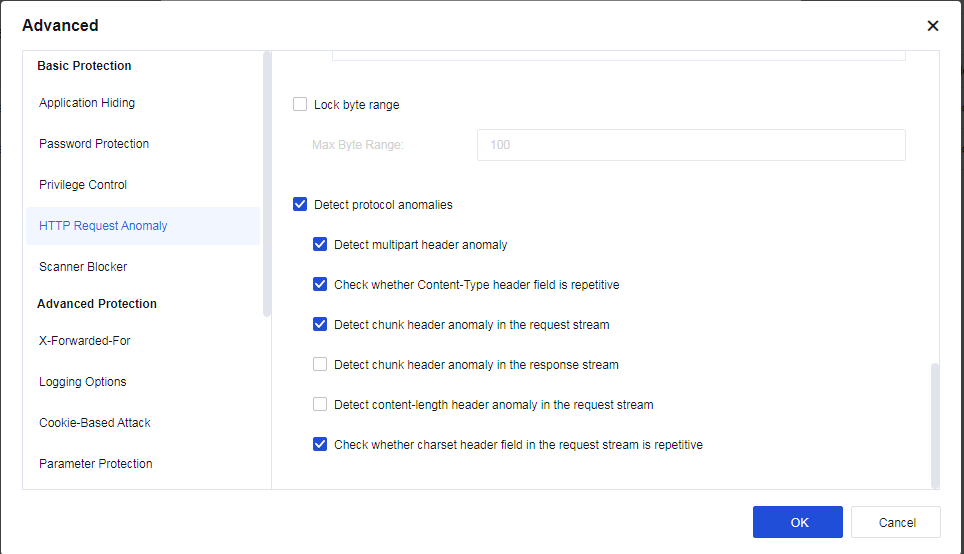
Scanner Blocker
To set behavior detection for a website scan. See the following figure.
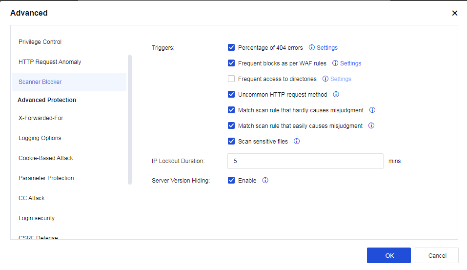
Triggers: Specify behaviors to be matched with visit data, based on which scanning behavior is determined. Follow-up processing is also provided. The following describes the behavior characteristics provided currently:
Percentage of 404 errors: It is calculated once every N responds. If the value exceeds the preset value, it is considered that a scanner is scanning the website. You can click Settings to configure the specific frequency and percentage, as shown in the following figure.
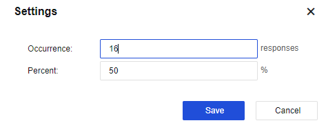
Frequent blocks as per WAF rules: Determine whether it is a scanner by judging the times that the Web App Protection rule intercepts a source IP in unit time. You can click Settings to configure the specific frequency, as shown in the following figure.

Frequent access to directories: Determine whether it is a scanner by judging the times that a source IP accesses the directory per second. You can click Settings to configure the specific frequency, as shown in the following figure.
Uncommon HTTP request method: The behavior that triggers the HTTP request method filter rules will be taken as one of the behavioral characteristics of the scanner. You need to enable the method filter.
Match scan rule that hardly causes misjudgment: Match an IP address with a strong scan rule and determine whether it is a scanner.
Match scan rule that easily causes misjudgment: Match an IP address with a strong scan rule and determine whether it is a scanner.
Scan sensitive files: Normally, a scanner will try to access sensitive files on various sites, such as configuration, password, database file, etc. By checking these sensitive files, it can be determined whether an IP address directs to a scanner.
IP Lockout Duration: When a source IP address is identified as a scanner, it will be blocked for a specified time indicated by this parameter. Data streamed from this source IP address will be blocked during the lockout period when it passes through the Network Secure device.
Server Version Hiding: When this function is enabled, the system will intelligently identify and hide the server’s version information.
Notice:
The Scanner Blocker function is not recommended in the following two scenarios:
- User’s IP address is to undergo source network address translation (NAT).
- Proxy servers are used to access business.
Advanced Protection
- X-Forwarded-For
When traffic passes through CDN or proxy. The corresponding X-Forwarded-For fields will be inserted into the HTTP header to record the real source IP address for the server. Select Enable, as shown below.
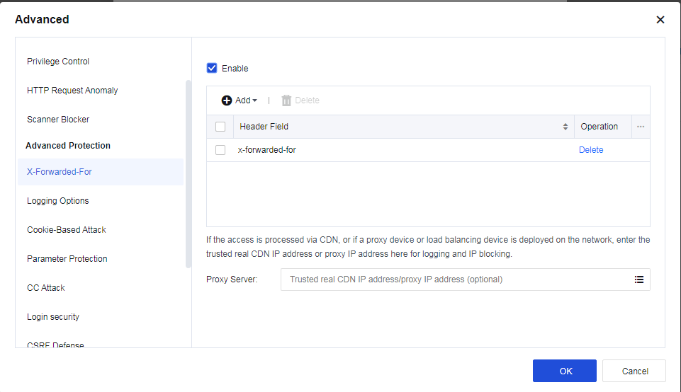
Header Field: Specify the HTTP header to which the X-Forwarded-For field inserts. Four fields can be identified: X-Forwarded-For, Cdn-Src-Ip, Clientip, and Other. You can also customize the configuration.
X-Forwarded-For: If the access is via CDN, or if a proxy device or loading balancing device is deployed on the network, enter the trusted real CDN IP or proxy IP address for logging and IP blocking.
- Logging Options
To record the logging types, as shown below.
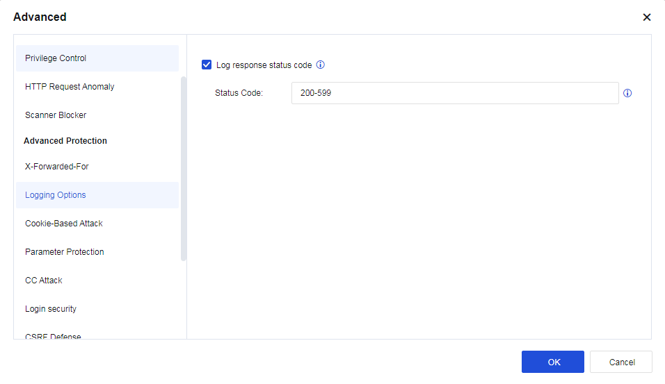
Status Code: Range from 200 to 599. The conditions to log response status code are as follows:
a) Attack is from the request side.
b) The detected attack action is allowed.
Notice:
When the Enable option on the Logging Options page is unchecked, this function remains valid if Log response status code is selected, and the policy that references the current template enables logging.
- Cookie-Based Attack
A cookie is a small text file stored on the client machine by the website when a client browses a website. Normally, it records the user ID, password, webpages browsed, dwell time, and other information on the client. When the same client re-accesses the website, the website can get relevant data by reading cookies and respond accordingly. When the client accesses the server, some important data will be kept in the cookie, which others may use, resulting in data leakage.
A cookie is used for the attack in two ways: stealing cookies and tampering with the cookie. The first way is to forge a legal identity to cheat the server, while the second way is to use the logic flaw in the server’s implementation.
Cookie-based attack protection detects whether the cookie has been stolen or tampered with based on the attributes of cookie and client data. This function can be used to protect all cookies or some cookie attributes.
The cookie’s attribute values and client communication can determine whether the cookie has been stolen or tampered with. The configuration is shown in the figure below.
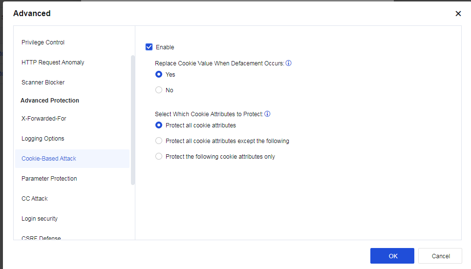
If Yes is selected for Replace Cookie Value When Defacement Occurs, the cookie value will be replaced with *. In Select Which Cookie Attributes to Protect, select Protect all cookie attributes, Protect all cookie attributes except the following, or Protect the following cookie attributes only.
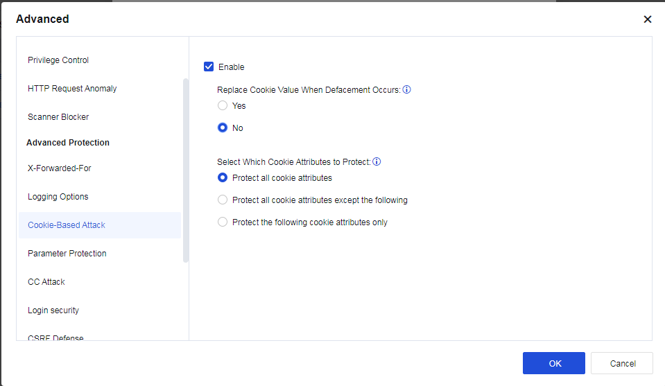
- Parameter Protection
Custom Parameter Protection: It is similar to the proactive protection function, except that parameters are customized. Regular expression matching is used. Specifically, when conditions of regular expressions are met, the matched action of reject will be triggered.
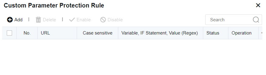
- CC Attack
It is to prevent CC attacks against websites. The configuration is as follows:
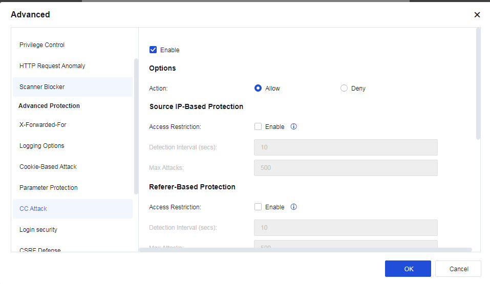
Source IP-Based Protection: When Enable is selected for Access Restriction, if the access count of a source IP address exceeds the threshold, subsequent access from this IP address will be denied.
Referer-Based Protection: When Enable is selected for Access Restriction, if the accumulative access count of the same URL in the Referer exceeds the threshold, access from any source IP address with the same Referer URL will be denied.
URL-Based Protection: When Enable is selected for Access Restriction, if the access count of a source IP address to the same destination URL exceeds the threshold, subsequent access from this IP address will be denied.
Custom Rule: Customize the CC protection rule.
- CSRF Defense
Cross-Site Request Forgery, or "one-click attack" or "session riding", is commonly abbreviated as CSRF or XSRF. It is an attack that compels end-users to perform unintentional operations on Web applications they have logged in to. By configuring CSRF protection, you can effectively prevent such attacks. The configuration interface is as follows.
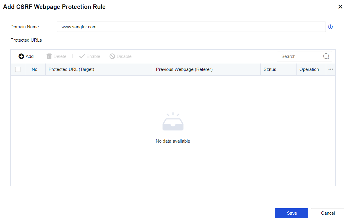
After configuring the domain name to be protected and adding the pages to be protected and the source pages allowed access, target pages are accessible only to the allowed Referrer, thus preventing CSRF attacks.
- Restrictive URL Access
It is to protect users’ key resources from being forcibly browsed by illegal clients. The configuration is as follows:

Access to the home page of a domain (www.sangfor.com.cn) is only allowed from www.sangfor.com/bbs/index.html. Other access methods are disallowed.
- Semantic Web Engine
Semantic Web engine allows algorithm detection against command injection, PHP code injection, Java code injection, XXE attack, WebShell upload, SQL injection, XSS attack, and backdoor scanning. Without rule detection, the detection rate is increased. See the figure below.
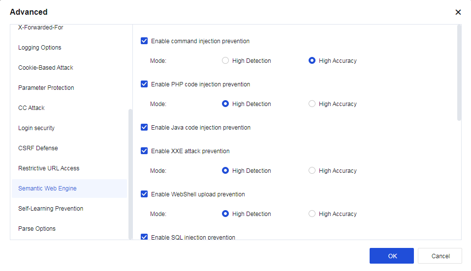
| Engine type | Note |
|---|---|
| Command injection prevention | Detect command injection attacks more effectively. If you are strict with security but accept particular false positives, High Detection is recommended. If you prioritize business stability, High Accuracy is recommended. |
| PHP code injection prevention | Detect PHP code injection attacks to unknown vulnerabilities more effectively with little dependence on rules. If you prioritize business stability, High Accuracy is recommended. |
| Java code injection prevention | Detects Java expressions more effectively to reduce false negatives. |
| XXE attack prevention | By performing grammar analysis and detection, the XXE security detection engine reduces false negatives and false positives to increase the Network Secure device’s block rate and security detection ability. |
| WebShell upload prevention | Reduce false negatives caused by buffer truncation. If you are strict with security but accept certain false positives, High Detection is recommended. If you prioritize business stability, High Accuracy is recommended. |
| SQL injection prevention | The SQL injection prevention engine is to improve the defense of the Network Secure device by enhancing its anti-bypass ability and reducing the false-positive rate. This function is enabled by default with High Accuracy selected and non-injection detection disabled, which applies to the scenarios with intensive SQL businesses. In light load scenarios, select High Detection and enable non-injection detection. |
| XSS attack prevention | The XSS attack prevention engine improves detection against XSS attacks and decreases the false positive rate. This function is enabled by default with High Accuracy selected, which applies to the scenarios where a lot of front-end pages are edited in the background. In scenarios with high-security requirements, High Detection is recommended. |
| Backdoor prevention | The backdoor prevention engine improves detection against the backdoor scanning attacks. This function is enabled by default with High Accuracy selected. In scenarios with high-security requirements, High Detection is recommended. |
Table 22: Description of Semantic Web Engine
9. Self-Learning Prevention
Self-learning prevention is to identify abnormal traffic and establish a baseline composed of feature models for the customer’s business traffic, thereby detecting traffic that is different from the business. For abnormal traffic it detects, it also attempts to identify known attacks. Characteristics that distinguish unknown malicious behavior from known attack behavior. This feature is turned off by default.
- Parse Options
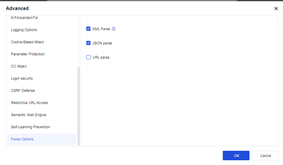
XML Parse engine-powered detection improves detection against XML attacks. The body part of the HTTP message is detected to identify the attack that bypasses authentication with WebShell transmitted through XML protocol.
JSON parse engine-powered detection improves detection against JSON attacks. The body part of the HTTP message is detected to identify the attack that bypasses authentication with WebShell transmitted through JSON protocol.
URL parse engine-powered detection improves detection against URL encoding attacks. The body part of the HTTP message is detected to identify the attack that bypasses authentication with WebShell transmitted through URL encoding.
Cloud-Delivered Protection
Cloud-Delivered Protection: Include IP Reputation and Cloud-Delivered IP Blocking. It is mainly used to correlate Neural-X, capture and block IP Reputation database temporarily to technically block attack behaviors fast and effectively increase the security ability of the Network Secure device.
Cloud-Delivered IP Blocking: When the Network Secure device is connected to Neural-X, Neural-X will analyze the data of the Network Secure device and then issue the data to be blocked temporarily. Such data will be displayed in the list of Blacklist and Temporary Blacklist. Select IP Reputation to enable this function, as shown below.
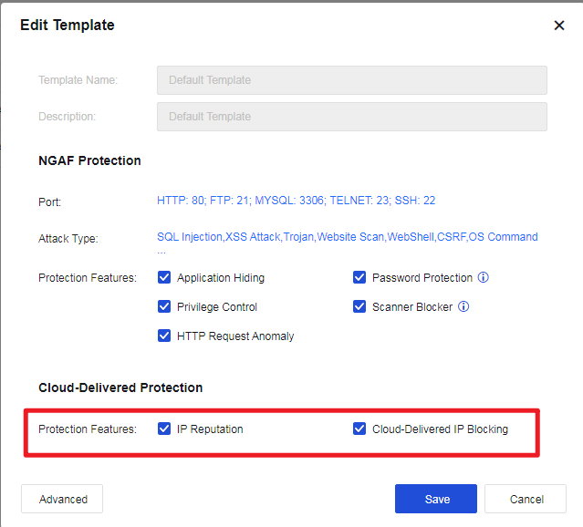
Note:
To enable IP Reputation, the Network Secure device must be Internet-accessible. The hacker IP addresses issued can be viewed in the IP Reputation(SOC > Specialized Protection).
Botnet
The botnet is used to discover and isolate PCs infected with viruses, Trojans, and other malicious software in the intranet. When viruses or Trojans try to communicate with external networks, Network Secure can recognize the traffic, and then block and log it according to user policies. Its configuration is as follows.
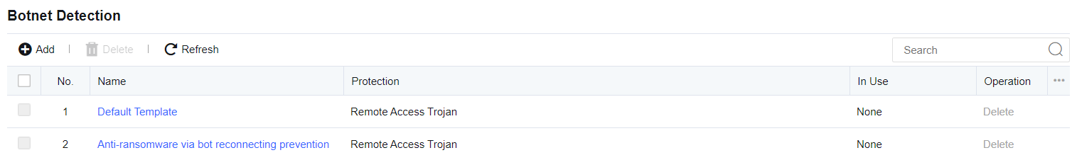
Click Objects > Security Policy Template > Botnet Detection to enter the Botnet Detection page to add or delete the botnet detection template. Click Add. The Add Botnet Detection Template page appears, as shown below.
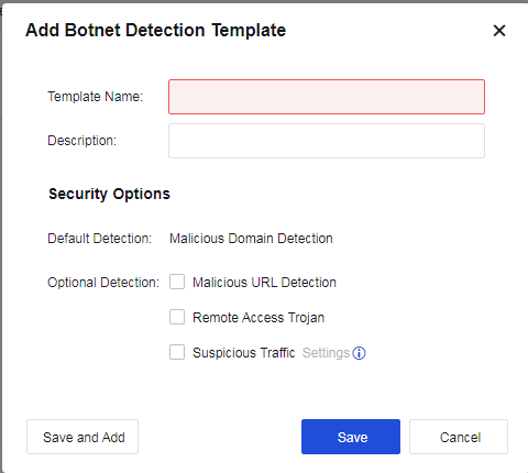
Template Name: Define the name of the template.
Description: Define the description of the template.
Security Options: Set the attack types to be detected.
Default Detection:
Malicious Domain Detection: Detect the malicious domain. This option is enabled by default and cannot be disabled.
Optional Detection:
Malicious URL Detection: Detect the malicious URL. This option is enabled by default and cannot be disabled.
Remote Access Trojan: Specify whether to perform remote Trojan detection against data sent by or requested from the protection zone.
Suspicious Traffic: There are two conditions. One is to detect port-protocol mismatches, and the other is to detect outbound traffic. Detected abnormal traffic is only logged but not blocked. Click Settings to select the abnormal traffic to be detected, as shown below.
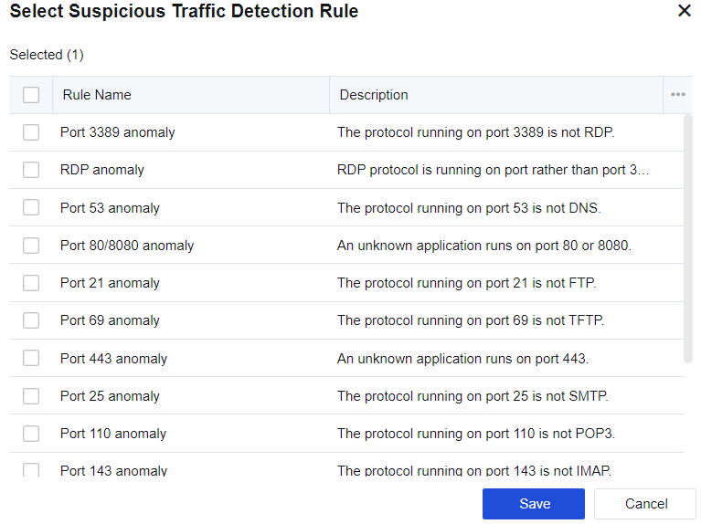
Outbound Traffic Trigger: It is a heuristic DoS attack detection method covering SYN flood, ICMP flood, DNS flood, and UDP flood attacks with the same source IP address. When outbound packets of these protocols exceed the threshold, the system considers them abnormal traffic and automatically starts packet capture. In the Select Suspicious Traffic Detection Rule dialog box, check Suspicious Outbound Traffic, and click Settings next to it. The detection threshold can be set as follows.
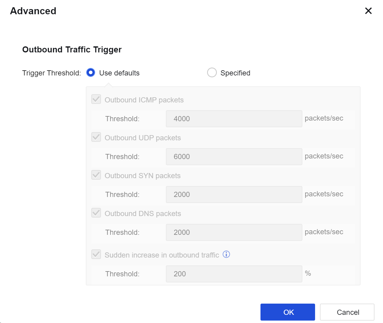
Notice:
- Abnormal traffic is only logged but not blocked.
- In Objects > Threat Signature Database > Security Database, you can set the action for each botnet rule. Disabled rules will not be rejected.
Content Security
The content security policy includes Email Protection, URL Filter, and File Protection. Email Protection detects email content, filters attachments, and verifies emails with Engine Zero. URL Filter filters the URL addresses of web pages that meet the preset conditions. File Protection is to filter files and verify files with Engine Zero. See the figure below.
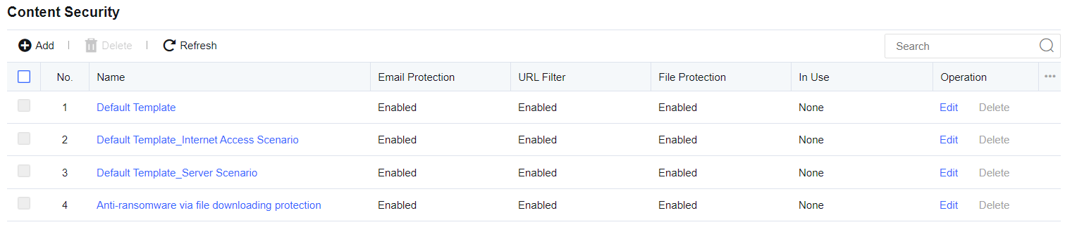
Click Objects > Security Policy Template > Content Security to enter the Content Security page to add or delete content security policy templates. Click Add. The Add Template page appears, as shown below.
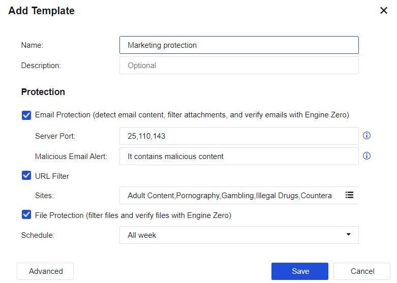
Name: Define the name of the template.
Description: Define the description of the template.
Email Protection: Detect email content, filter attachments, and verify emails with Engine Zero.
Server Port: There are three ports (25, 110, and 143) by default. For an encrypted email protocol, enable decryption for Internet access.
Malicious Email Alert: When the user receives a malicious email, this alert will be added to the email subject.
URL Filter: Filter the URL addresses of web pages meeting the preset conditions.
File Protection: Filter files and verify files with Engine Zero.
Schedule: Indicate a filter condition. The policy can take effect only if filtering is performed within a specified point in time. It will call the defined time object on the Objects > Schedule page.
Advanced: Set relevant filter conditions, filter types, and thresholds for Email Protection, URL Filter, and File Protection.
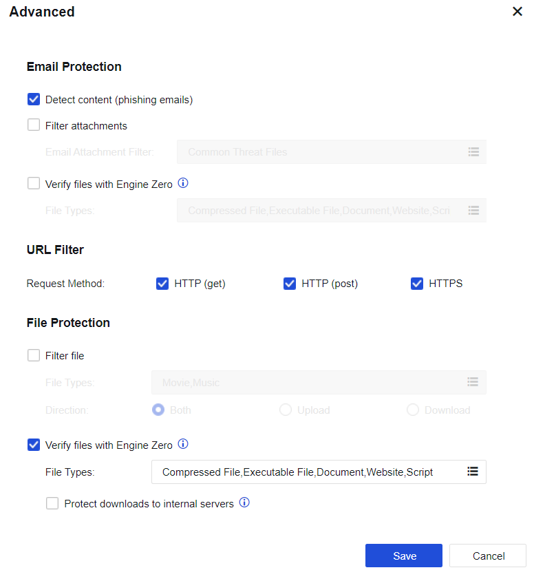
Email Protection
Detect content: If consecutive detection failures of an abnormal account exceed the threshold, the account will be identified as a threat. If Deny is selected on the network security policy, e-mails from the abnormal account will be rejected.
Filter attachments: Set the types of email attachments to be filtered. If Deny is selected on the network security policy, e-mails with attachments containing the file types specified in this list will be rejected.
Verify files with Engine Zero: Define the types of attachments requiring antivirus treatment. Only the attachment types in this list are subject to antivirus treatment.
URL Filter
Request Method: Select HTTP (get), HTTP (post), or HTTPS filter for specified URL categories. For example, to prevent LAN users from browsing certain types of web pages, select HTTP (get); to allow LAN users to browse web pages but ban file upload (BBS posting), select HTTP (post).
Select HTTPS and HTTP (get), or HTTPS and HTTP (post) to restrict access to the HTTPS website or only allow to browse, while file uploading is not allowed.
Note:
The HTTPS ontion is not enable by default. It’s necessary to enable the HTTPS option , so that the content security function is working with HTTPS protocol.
File Protection
Filter file: Filter files of certain formats uploaded or downloaded through HTTP.
Verify files with Engine Zero: Define the extensions of files requiring antivirus treatment. Only the file types in this list are subject to antivirus treatment.
Protect downloads to internal servers: If the protected-server attempts to connect to an external HTTP server, the download behavior will be subject to Engine Zero Based File Verification.
Threat Signature Database
The threat signature database is provided for security policy templates to call the built-in security rule database or customize rules for quick response to attack behaviors.
Security Database
The security database is built into the Network Secure device and can be updated in the effective period of upgrade license. It includes WAF Signature Database, IPS Signature Database, Malware Signature Database, and Passive Vulnerability Scan Database. You can select different types of identification databases for different settings.
WAF Signature Database
WAF Signature Database covers attack packet features of the application layer, including SQL injection, XSS attack, website Trojan, website scanning, WebShell, cross-site request forgery, OS command injection, file inclusion attack, directory traversal attack, information disclosure attack, and whole-site Web system vulnerability. When passing through the device, these attack packets can be intercepted based on user settings to protect the server, as shown in the figure below.
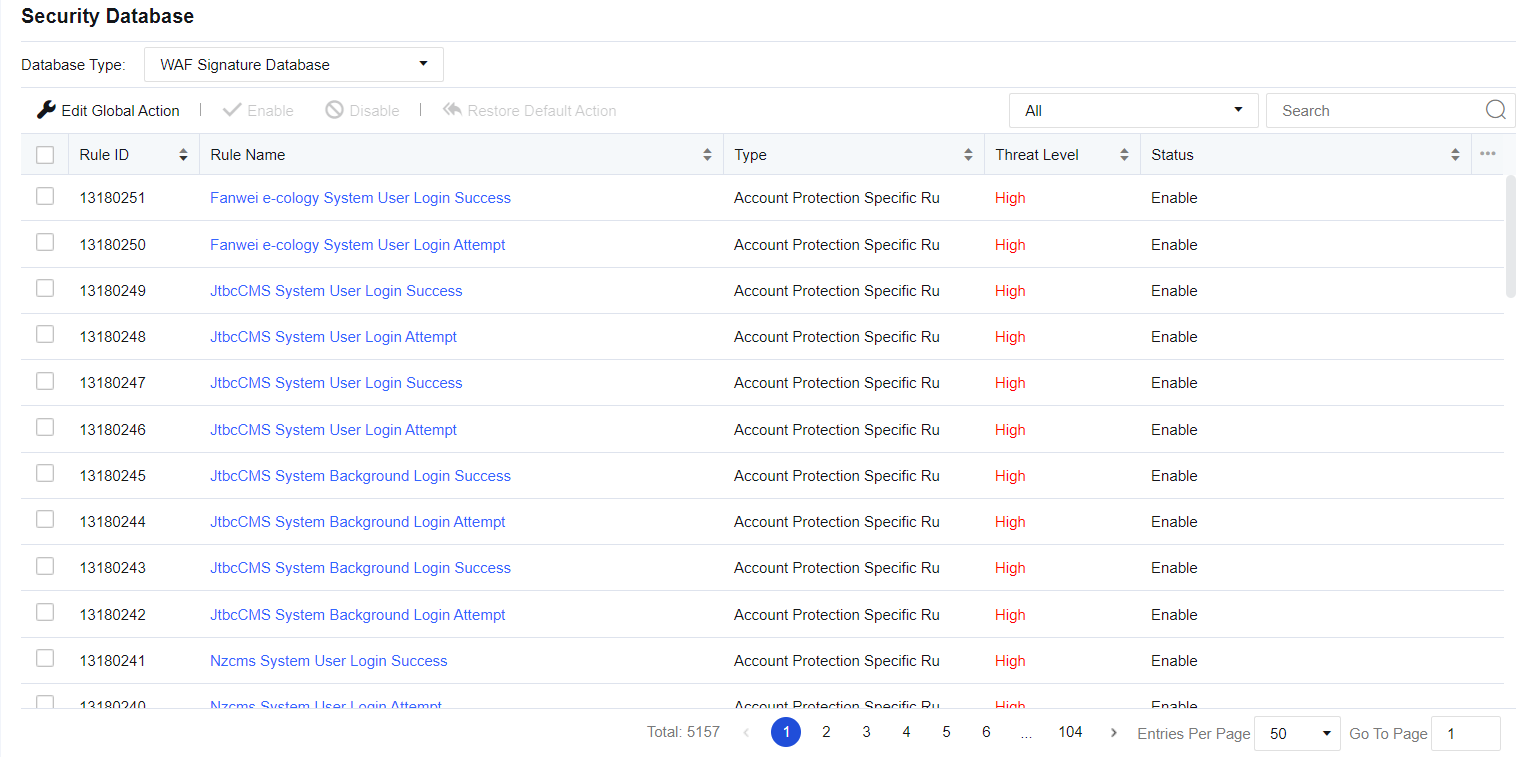
Click Edit Global Action to modify WAF protection rules in a unified manner. If Default action (initial system state) is selected, the system’s rule state is retained. If Block if attack detected is selected, the actions for all protection rules will be set to Enable, block after detection. Rules with the medium hazard level will be passed under the default status of the system, while rules of any hazard level will be intercepted after strict detection is enabled. See the figure below.
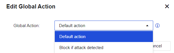
Type shows the rule database of the current protection type. Click the drop-down box next to the search box to view the corresponding rule ID according to the protection type. Rule Name shows the corresponding name of the protection rule, as shown in the following figure.
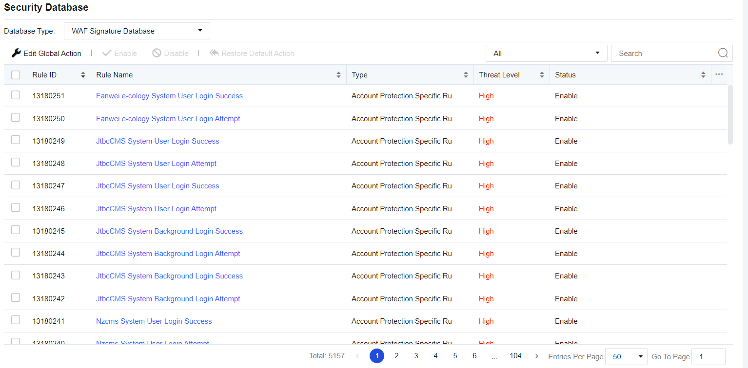
Rule Name: Show the name of the protection rule.
Type: Display the protection type mapping to the current protection rule, such as SQL injection.
Threat Level: Describe the severity of the current vulnerability. It includes three levels: High, Medium, and Low. The higher the level, the higher the severity.
Status: Describe the actions taken by the device when detecting an attack, including Enabled. Block if attack detected, Enabled. Allow if attack detected, Enable, and Disable. This status can be customized. Click a rule name to go to the Edit Rule page, as shown in the figure below.
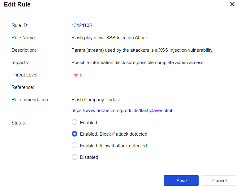
Enabled. Block if attack detected: Indicate that the current rule is enabled. When an attack is detected, the corresponding packet is blocked.
Enabled. Allow if attack detected: Indicate that the current rule is enabled. When an attack is detected, the packet is logged but not blocked.
Disabled: Indicate that the current rule is disabled. When the rule is disabled, the device does not detect the rule.
IPS Signature Database
IPS Signature Database covers the features of attack packets that exploit system and application vulnerabilities. When passing through the device, these attack packets can be intercepted based on user settings to protect the server, as shown in the figure below.
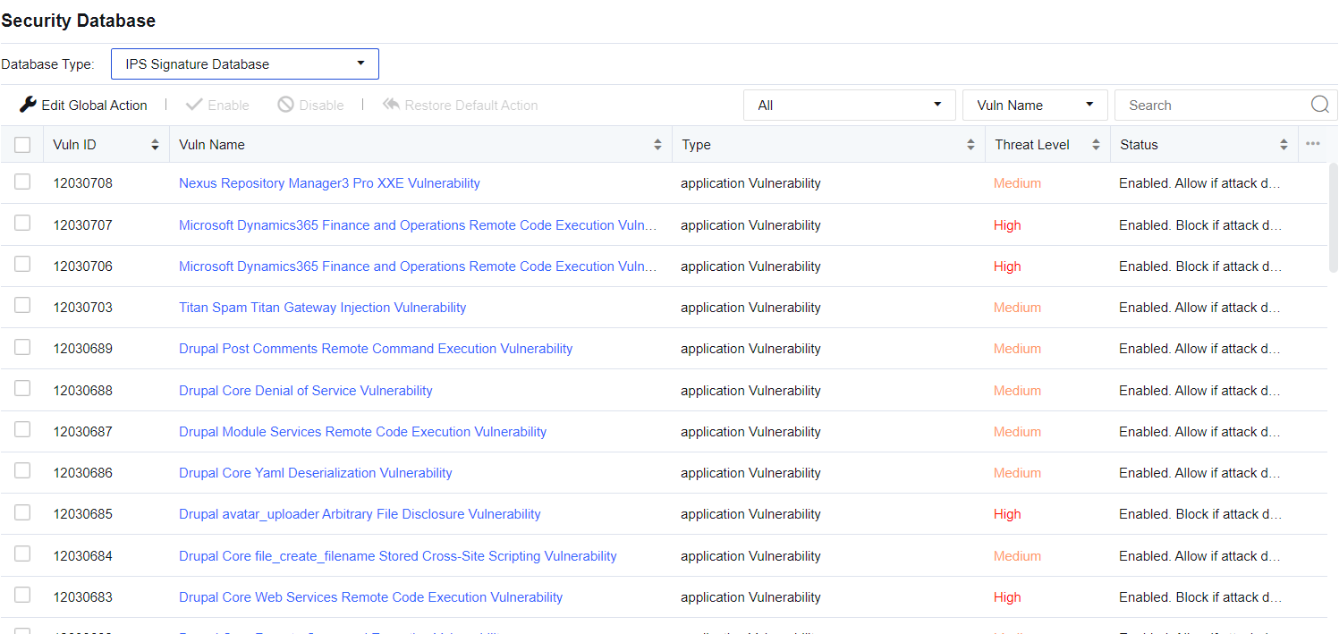
Edit Global Action: Used for unified modification of IPS signature identification rules if Default action (initial system state) is selected, the system’s rule state is retained. If Block if attack detected is selected, the actions for all identification rules will be set to Enable, block after detection. Rules with the medium hazard level will be passed under the default status of the system, while rules of any hazard level will be intercepted after strict detection is enabled.

Restore Default Action: Restore all modified rules to the default state.
The device provides the search function for vulnerability rules against vulnerability attacks. You can search by setting the Vulnerability category and query category and entering keywords (such as the vulnerability name and ID).
Vuln ID: This shows the ID of the current vulnerability. It allows you to check the vulnerability ID in the report center when a IPS event being triggered. By querying the vulnerability ID here, you can pass this rule.
Vuln Name: This shows the name of the vulnerability.
Type: Show the current vulnerability type, such as Backdoor.
Threat Level: Describe the severity of the current vulnerability. It includes three levels: High, Medium, and Low. The higher the level, the higher the severity.
Status: Describe the action taken by the device when detecting an attack against the vulnerability, including Enabled. Block if attack detected, Enabled. Allow if attack detected, and Disable. This action can be customized. Click a vulnerability name to go to the Edit Signature page, as shown below.

Enabled. Block if attack detected: Indicate that the current rule is enabled, and when an attack against the vulnerability is detected, the corresponding packet is blocked.
Enabled. Allow if attack detected: Indicate that the current rule is enabled. When an attack against the vulnerability is detected, the packet is logged but not blocked.
Disable: Indicate that the current rule is disabled. When the rule is disabled, the device does not detect the vulnerability.
Notice:
The pass and block attributes of the vulnerability signature database have been configured before delivery. When you need to modify a rule, edit the rule.
Malware Signature Database
Malware Signature Database contains 20 rule protection types, including Trojan, mining, phishing, worm, illegality & immorality, infectious viruses, backdoor software, malicious URL, advertising software, Infostealer, malware, network security, spyware, hacking tools, malicious script, Trojan remote control, ransomware, Rootkit, rogue software, and botnet.
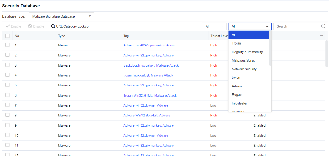
Rule Status: View all rules under the enabled and disabled status.
Type: Contain 20 rule protection types, including Trojan, mining, Phishing, worm, Illegality & Immorality, Virus, backdoor, malicious_website, Adware, Infostealer, Malware, Network Security, Spyware, Hacktool, Malicious Script, trojan remote control, ransomware, Rootkit, Rogue, and botnet.
Enable: Enable the selected rule database.
Disable: Disable the selected rule database.
Passive Vulnerability Scan Database
Passive Vulnerability Scan Database covers some vulnerability rules for discovering security vulnerabilities on the user’s network and presenting users with a report stating the harm and solution of the vulnerabilities. Vulnerability rules include the Web server vulnerability, Database server vulnerability, FTP server vulnerability, Mail server vulnerability, and SSH server vulnerability. It performs real-time vulnerability analysis on the specified data, as shown in the following figure.
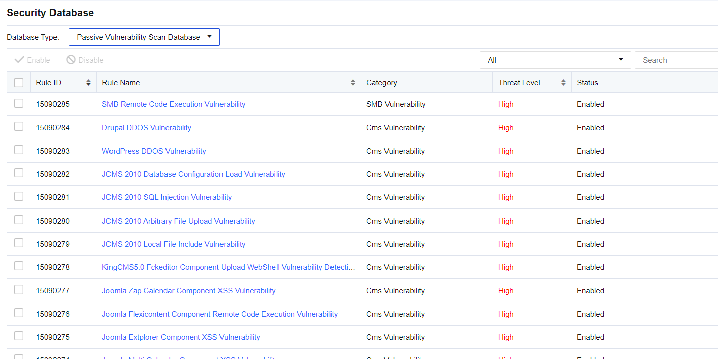
You can enter the rule name or rule ID in the upper right corner to search for a rule.
Click the drop-down box next to the search box to show the vulnerability types covered by the device. You can choose to filter the type of rules as needed.
You can view rule details by clicking a rule name.
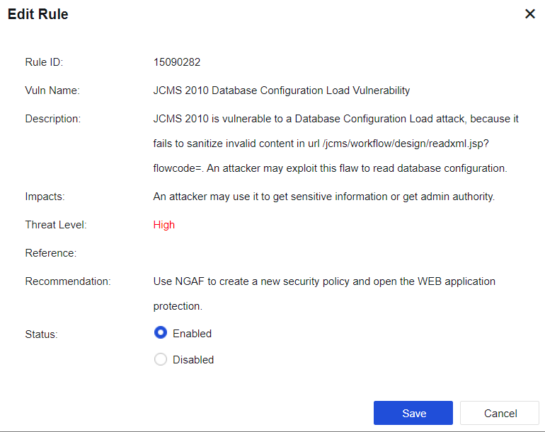
Vuln Name: This shows the name of the vulnerability.
Description: This shows a detailed explanation of the vulnerability.
Impacts: This shows the consequence that the vulnerability may lead to.
Threat Level: Describe the severity of the current vulnerability. It includes three levels: High, Medium, and Low. The higher the level, the higher the severity.
Recommendation: Show the method available to avoid the vulnerability.
Status: Include Enable and Disable. When the vulnerability is disabled, the device does not detect this vulnerability.
Custom Database
According to the manual custom signature database, the undiscovered attack behavior can be protected in time. At present, it supports a custom WAF signature database, custom IPS signature database, custom malware signature database
Custom WAF Signature Database
Custom WAF Signature database includes the custom Web Application Protection Rule, CC Attack Protection Rule, and Password Protection Rule. The Custom WAF Signature tab is shown below.

Click Add to enter the Add Signature dialog box, as shown in the following figure.
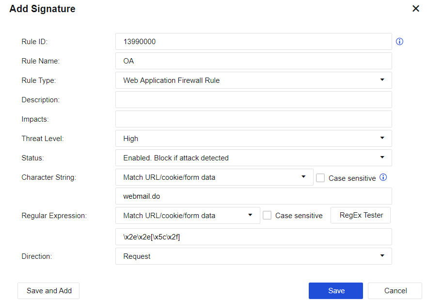
Rule Name, Description, and Impacts can be customized based on the situation.
Rule Type: Web Application Protection Rule, CC Attack Protection Rule, and Password Protection Rule can be selected.
Threat Level: The available three levels (High, Medium, and Low) define the severity of the rule.
Status: Three types are provided, including Enabled. Block if attack detected, Enabled. Allow if attack detected, and Disable.
Enabled. Block if attack detected: Indicate that the current rule is enabled. When an attack is detected, the corresponding packet is blocked.
Enabled. Allow if attack detected: Indicate that the current rule is enabled. When an attack is detected, the packet is logged but not blocked.
Disable: Indicate that the current rule is disabled. When the rule is disabled, the device does not detect the rule.
Character String, Regular Expression, and Direction are used to set the rule content. The previous two options can be empty, indicating that they are not used for matching.
Custom IPS Signature Database
On the Custom IPS Signature tab, click Add to enter the Add Signature dialog box, as shown in the following figure.
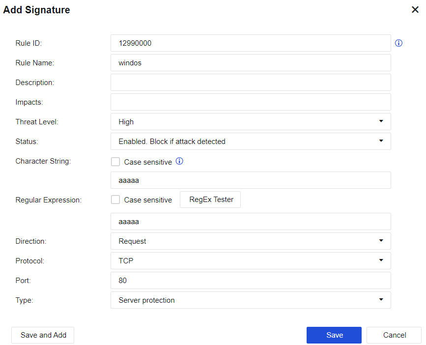
Rule Name, Description, and Impacts can be customized based on the situation.
Threat Level: The available three levels (High, Medium, and Low) define the severity of the rule.
Status: Three types are provided, including Enabled. Block if attack detected, Enabled. Allow if attack detected, and Disable.
Enabled. Block if attack detected: Indicate that the current rule is enabled. When an attack is detected, the corresponding packet is blocked.
Enabled. Allow if attack detected: Indicate that the current rule is enabled. When an attack is detected, the packet is logged but not blocked.
Disable: Indicate that the current rule is disabled. When the rule is disabled, the device does not detect the rule.
Character String, Regular Expression, Direction, Protocol, and Port are used to set the rule content and data matching conditions. The previous two options can be empty, indicating that they are not used for matching.
Type: Select the types of objects protected by the intrusion prevention rules.
Custom Malware Signature Database
Custom Malware Signature database allows you to customize the URLs that need to be detected and protected against the malware, as shown in the figure below.
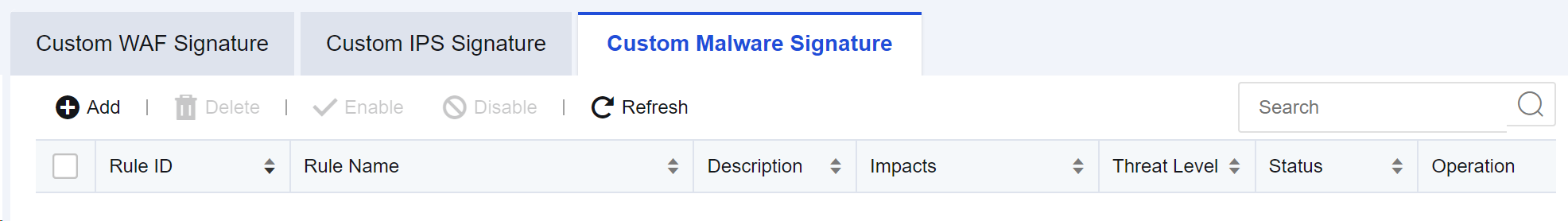
On the Custom Malware Signature tab, click Add. Then, the Add Signature dialog box appears, as shown below.

Rule ID: Custom rule ID.
Rule Name, Description, and Impacts can be customized based on the situation.
Threat Level: The available three levels (High, Medium, and Low) define the severity of the rule.
Status: Two types are provided, including Enabled. Block if attack detected and Disable.
Domain/URL: Define the domain name/URL that the rule needs to match.
Content Identification Database
The Content Identification database can mainly identify apps, URLs, file types, etc. The safety of contents is tested by identifying different contents.
Application Signatures Database
The Application Signatures database is mainly used to identify app data and protect apps by identifying different apps.
Application Signatures
To judge and detect the app category of Internet data. It can detect the app category according to the signature value of the data packet or multiple conditions, such as protocol, port, direction, data packet length matching, and data packet content matching. Also, it can detect app categories that cannot be distinguished by port or protocol, such as QQ, P2P, etc.
The Application Signatures database is divided into the built-in database and the custom database. The built-in database has built-in rules and apps, and the custom database has custom rules and custom apps. The built-in database cannot be modified; which is updated regularly by the device.
Updating the built-in database requires serial number authorization to ensure the device can access the Internet. The custom database can be added, deleted, modified, etc. A custom definition can cite multiple rules.
In Policies > Access Control > Application Control > Policies, you can cite app signature rules to control relevant applications.
Viewing application signature rules
Navigate to Objects > Content Identification Database > Application Signatures and click the Application Signatures tab.

Total: Show the number of app rules in the device’s current internal rule signature database.
Current Database Released On: Show the release date and time of the current version of the internal rule signature database.
Update Service Expires On: Show the validity period for the upgrade of the internal rule signature database.
Category: Show the categories of app signature rules, such as IM and games.
Select the correct app category. Applications show specific applications included in the current app category. They belong to a sub-category under the large app category, such as QQ and MSN in IM.
Select the rule type to be queried in Filter: Select Status to filter all rules that meet the conditions; select Enabled to filter enabled rules that meet the search conditions; select Disabled to filter disabled rules that meet the conditions. In Search, enter the rule keyword to be queried (e.g., set "QQ" as the filter condition).
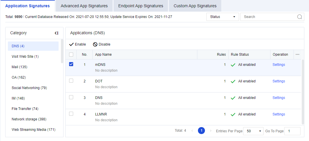
Enabling/Disabling application signature rules
Navigate to Objects > Content Identification Database > Application Signatures, click theApplication Signatures tab. Filter the rules to be set. For example, enter "QQ" to filter QQ related apps, as shown in the following figure.
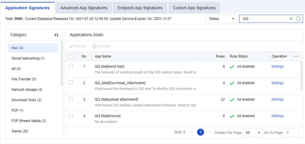
Select the specific app and click Enable or Disable. You can disable or enable all QQ login rules.
If you want to disable or enable a rule in a specific app, such as disabling a rule in "QQ", click Settings. The signature rules editing box will appear, listing all relevant rules of QQ. Select a rule and click Enable or Disable to disable or enable the rule.
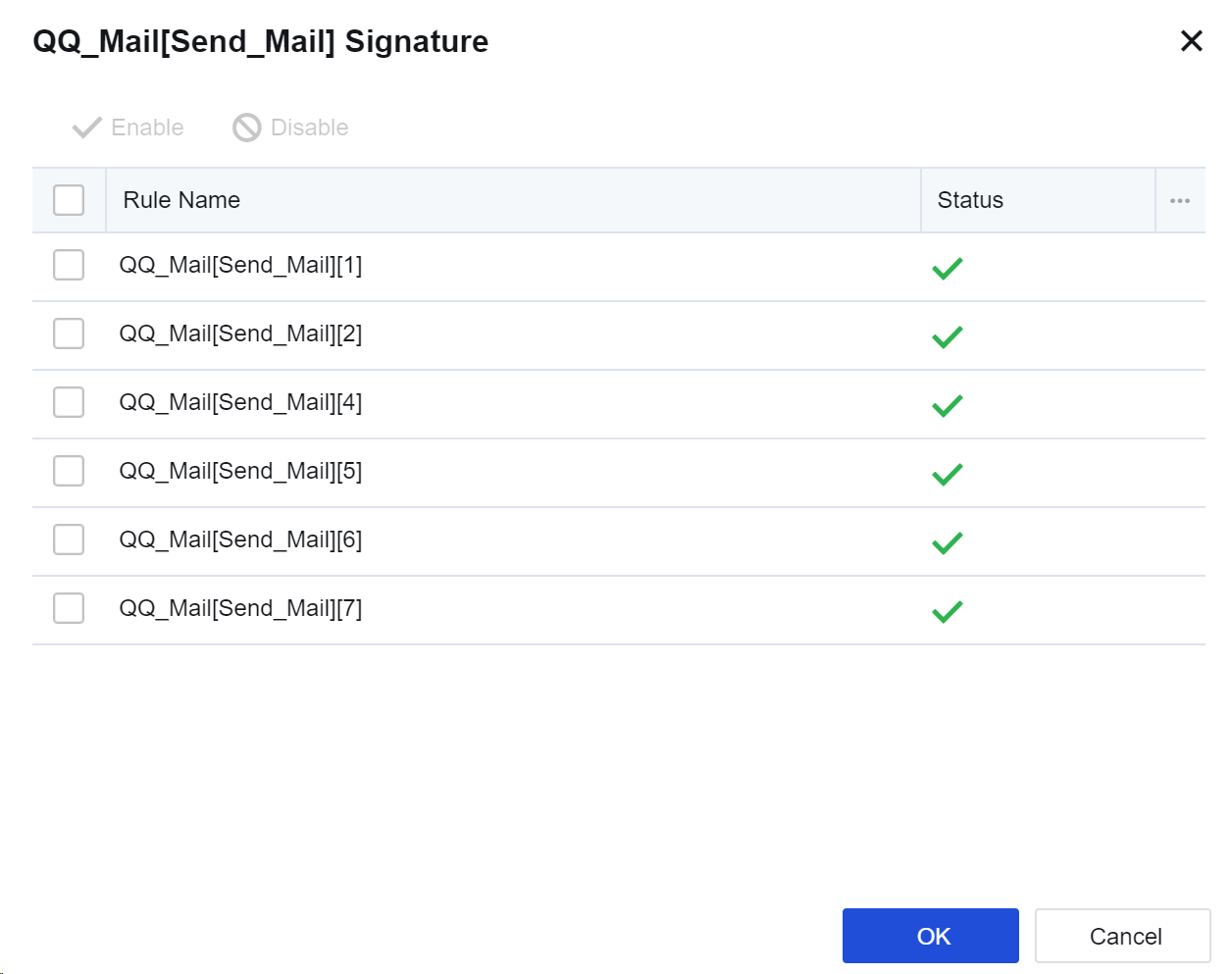
Notice:
- The app signature rules of some basic protocols (such as HTTP) cannot be disabled. If such basic protocols are disabled, data identification based on HTTP will be affected. Therefore, such rules cannot be disabled.
- Here, disabling the rules is not to block apps. For blocking rules, please refer to Chapter 8.4.4 Content Security. In this case, if we disable QQ, the device will not identify the QQ app. Under normal circumstances, you are not advised to disable these rules. They may be needed in troubleshooting scenarios.
- The app signature database supports IPv6 and can recognize common applications in the IPv6 environment.
Advanced App Signatures
Advanced App Signatures database is used to identify various app categories of Internet data. It has a different judgment method from the Application Signatures database, which can identify some encrypted data, such as plaintext or ciphertext of P2P apps, Skype, SSL, Sangfor VPN data identification, and data of proxy tools. The configuration is shown in the figure below.

Enabling/Disabling advanced app signature rules
Navigation to Objects > Content Identification Database > Application Signatures, click the Advanced App Signatures tab, as shown below.
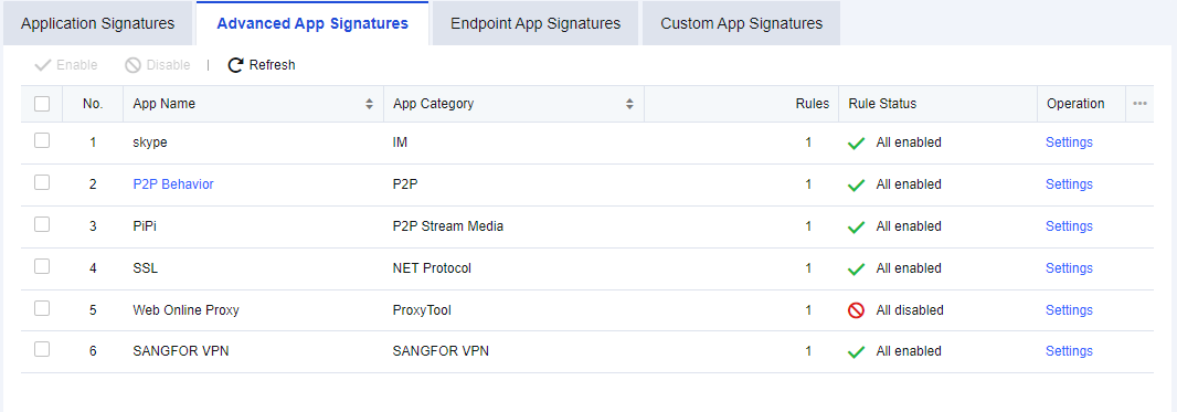
Select the specific app, for example, "skype" and click Disable or Enable. You can disable or enable the intelligent identification rules of Skype.
If you want to disable or enable a rule in a specific app, such as disabling a rule in the "skype", click Settings. The signature rules editing box will appear, listing all relevant rules of "skype". Select a rule and click Enable or Disable to disable or enable the rule.
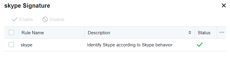
Editing P2P behavior identification rules
P2P behavior identification rules supplement app feature identification and intelligently identify P2P data that cannot be recognized in the app signatures database. P2P behavior rules can be edited. Click P2P Behavior, and the Advanced App Signatures dialog box appears.
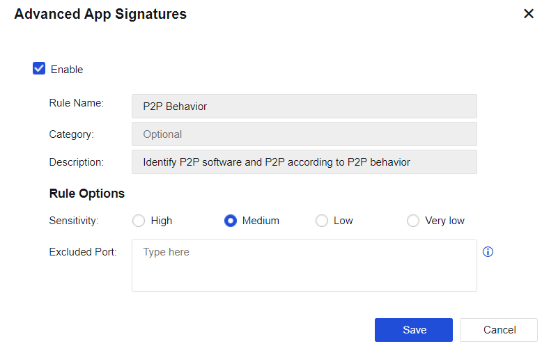
Enable: You can select this option to enable the current rule.
Rule Name, Category, and Description cannot be edited.
Sensitivity: Set the sensitivity of the rule. Four options are provided: High, Medium, Low, and Very low. You can adjust the detection sensitivity as needed. Intelligent P2P identification may lead to misjudgment, so sensitivity is used to set the judgment standard. The sensitivity decreases from high to extra-low. You can adjust the sensitivity level according to the identification of specific data. For example, if there is much data, and the ports for data connection are random high-end ports with uncertain target addresses, these data may be unidentified P2P data. In this case, you may use higher sensitivity. If some apps do not contain P2P data but are identified as P2P, the sensitivity level may be set higher. In this case, you can lower the sensitivity level properly.
Excluded Port: Specify the excluded port. If the target data port is excluded, the device does not perform P2P intelligent identification on such data. It can avoid misjudgment to some extent.
Endpoint App Signatures
Endpoint App Signatures database is used to identify various proxy tools app categories and custom endpoint app, as shown in the following figure:

Viewing Endpoint app signature rules
Navigate to Objects > Content Identification Database > Application Signatures, select the Endpoint App Signatures tab.

Total: Show the number of app rules in the device’s current internal rule signature database.
Current Database Released On: Show the release date and time of the current version of the internal rule signature database.
Update Service Expires On: Show the validity period for the upgrade of the internal rule signature database.
Category: Show the categories of proxy tools app signature and custom endpoint app.
In Search, enter the rule keyword to be queried (e.g., set "Psiphon" as the filter condition).
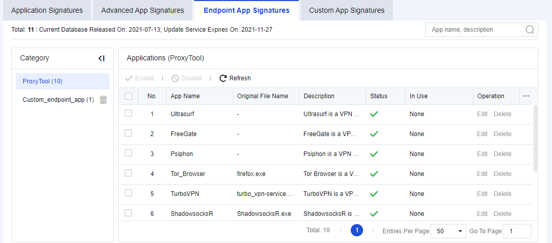
Enabling/Disabling endpoint app signature rules
Navigate to Objects > Content Identification Database > Application Signatures, click the Endpoint App Signatures tab.
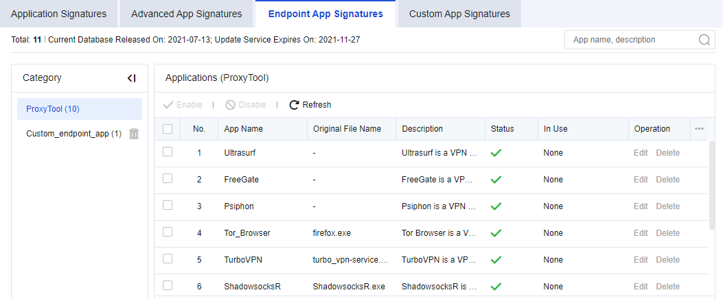
Select the app name "Ultrasurf" and click Disable or Enable. You can disable or enable the endpoint app rules of Ultrasurf.
Custom App Signatures
To customize the app signature rules. You can customize apps not covered by the built-in app signature database.
The custom app signature rules can be defined by data direction, IP address, protocol, and port. You can perform operations on custom applications, such as add, delete, enable, disable, import, and export as the administrator.
Navigate to Objects > Content Identification Database > Application Signatures, click the Custom App Signatures tab.
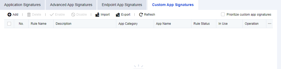
Example: You must provide traffic assurance for company mail. However, when selecting the app category, you cannot select the company mail alone. In this case, you can customize a company mail app.
-
On the Custom App Signatures tab, click Add. The Add App Signature dialog box appears. Set related parameters by following the steps.
-
Enable the rule and set the Basic Attributes of the app, including the Rule Name, Description, Category, and App Name. You can select the existing category or customize a category.
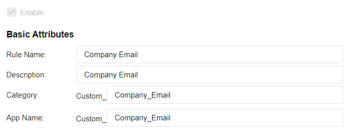
- Set the features of matching packets.
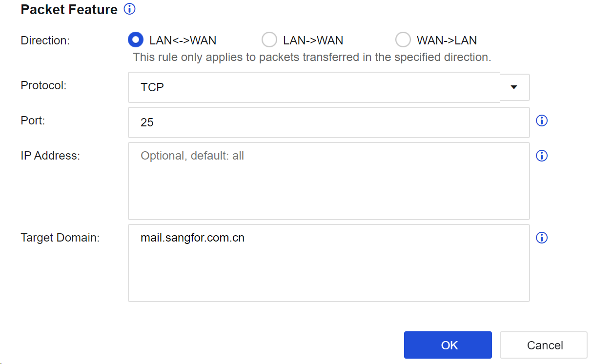
Direction: Specify the direction of data passing through the device. The rule only applies to packets transferred in the specified direction.
Protocol: Specify the type of protocol used for sending data. In this example, the TCP is used for mail sending.
Port: Specify the destination port accessed by the data. In this example, the mail is sent through the TCP25 port.
IP Address: Specify the source IP, destination IP, or destination IP after proxy identification.
Target Domain: Specify the target domain name address that packets access. In this example, enter the domain name email address of the company, such as "mail.sangfor.com".
- Click OK to complete the settings of this rule.
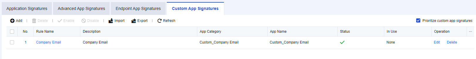
-
Prioritize a custom app signature rule. Because the built-in app signature database also provides a mail identification rule. If the built-in rule is prioritized, the data may first match this mail identification rule instead of the custom app signature rule ("Company Email"). Therefore, you should prioritize the custom app signature rule. To do this, select Prioritize custom app signatures on the Custom App Signatures tab.
-
Choose Bandwidth Channel and set the guaranteed channel of this app, ensuring that the bandwidth required for the mail is sent from the company email address.
Notice:
When setting the custom app signature rule, it is recommended to add identification information, including destination port, IP address, and domain name. If identification conditions are too broad, they may conflict with the built-in application identification rules and lead to confusion. As a result, some control and audit rules may fail.
URL Category Database
URL category database includes the built-in URL database and custom URL database. The built-in URL database is updated regularly by the device. Such updates require an S/N license, and the device must be able to access the Internet. The custom URL database can be added, deleted, and modified.
Navigate to Objects > Content Identification Database > URL Category. On the URL Category page, you can view the release date and time of the current version of the built-in URL category database and the expiry date of the built-in URL update. See the figure below.
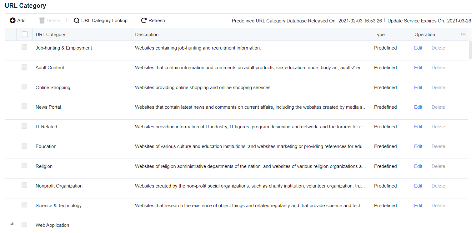
Add URL Category
To set custom URLs. On the URL Category page, click Add to enter the Add URL Category dialog box.
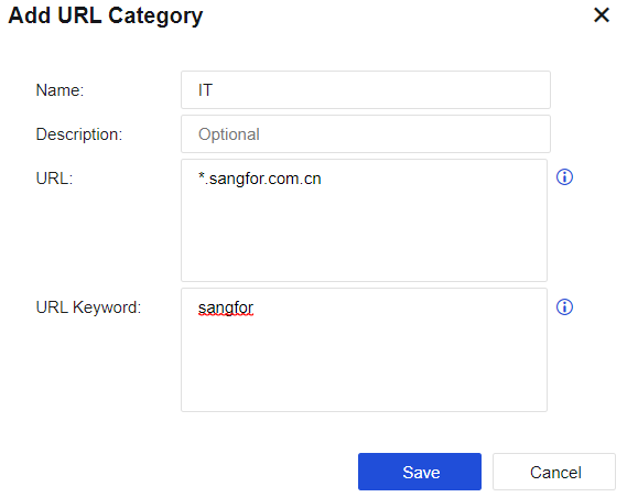
Name: Define a name easy to understand.
Description: Define a description easy to understand.
URL: Add the URL that needs to be set. A URL group can contain multiple URLs, and URLs support wildcard matching.
URL Keyword: Automatically matches the URL group based on the keywords in the URL. If the domain name being accessed contains the set keywords, it is identified as the URL group. The matching priority of domain name keywords is lower than the built-in URL database and custom URL database.
Notice:
- An asterisk (*) is used as the wildcard. For example, if you want to set a URL to indicate Sina subpages, including Sina News (news.sina.com.cn), Sina Sports (sports.sina.com.cn), and Sina Entertainment (ent.sina.com.cn), enter "*.sina.com" in URL.
- The asterisk (*) only indicates the matching of L1 domain names and can only be placed in the front of the URL (not in the middle). Otherwise, the URL will not take effect.
- The URL category database does not support IPv6. Web filter does not process URLs in the IPv6 environment, and access to IPv6 websites is not logged.
URL Category Lookup
Navigate to Objects > Content Identification Database > URL Category. On the URL Category page, click URL Category Lookup. The URL Category Lookup dialog box appears. Enter the domain name that you want to query and click Search. The result shows the URL category you are searching for. The system does not support fuzzy queries for URL category lookup. See the figure below.
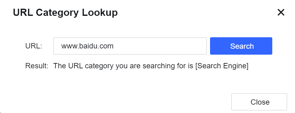
Edit URL Category
To modify a custom URL category or a built-in URL category. When editing the custom URL category, you can edit the Description, URL, URL Keyword, and other parameters of this URL category.
When editing the built-in URL category, you are not allowed to edit the name and description of the URL category, nor the existing URLs in the built-in database. You can only add a URL for the URL parameter and a keyword for the URL Keyword parameter as a supplement to the built-in URL database.
Delete URL Category
To delete a custom URL category. The built-in URL categories of the device cannot be deleted. On the URL Category page, select the custom URL database and click Delete to delete the corresponding URL categories.
File Types
To define the required file types. The file types can be applied to file filtering in Objects > Security Policy Template > Content Security to restrict file upload/download through HTTP and FTP, or set the traffic control for file type upload/download in Policies > Bandwidth Management > Bandwidth Channel > Bandwidth Channel.
Navigate to Objects > Content Identification Database > File Types, select the File Types tab. See the figure below.
On the File Types tab, click Add. The Add File Type dialog box appears, as shown in the following figure.

Name: Specify the name of the file type.
Description: Specify the description of the file type.
File Extension: Enter the suffixes of files in the text box, such as "*.mp3" or "mp3".
Notice:
The device provides most file types, including movie, music, image, text, compressed files, and webpage by default. If they cannot meet the requirements, manually add other types.
Email Attachment Filter
To define a filter type for email attachments. After the filter type is set, some email attachments with threat behaviors can be filtered, thus keeping the information of recipients secure. See the figure below.
Click Add to create a filter type for email attachments, as shown in the following figure.
Name: Specify the name of the file type.
Description: Specify the description of the attachments.
File Extension: Enter the suffixes of files in the text box, such as "*.mp3" or "mp3".
SLB Server Pools
You can add an SLB server pool as the destination IP address for destination NAT or bidirectional NAT. An IP address is selected from the server pool as the destination IP address for NAT based on the weighted round-robin algorithm, ensuring balanced traffic distribution across servers.
On the SLB Server Pools page, click Add to add an SLB server pool, as shown in the following figure.
Algorithm: Weighted Round Robin is supported. Weighted Round Robin is a commonly used algorithm in Layer 4 load balancing. It dynamically adjusts traffic distribution based on server loads. The principle of the weighted round-robin algorithm is as follows:
-
Assign each server a weight. The higher the value, the more traffic the server can handle.
-
Rotate through each server to distribute traffic based on the server’s weight.
-
Deduct the greatest common divisor of the total weight from the server’s weight after each traffic distribution to adjust traffic distribution in the next rotation.
-
Remove a server from the rotation list when its weight reduces to 0. When the weights of all servers are 0, the weights are reset to their initial values for a new rotation.
Note:
You can configure up to 16 SLB server pools. Each pool can contain 32 combinations of IP addresses and ports at most.
After adding an SLB server pool, you can select it in Translated Data Packet under Policies > NAT when adding destination NAT or bidirectional NAT, as shown in the following figure.
IP Location Database
The IP address database includes all IP addresses covering Internet Service Provider (ISP) IP addresses and regional IP addresses. Here, this database allows you to query the ISP IP address range and IP location.
ISP IP Address Range
To set an IP address range of the ISP. The IP address range can be called when being deployed in route mode.
On the ISP tab, click Add. Then, the Add ISP dialog box appears. To add an ISP address range, enter the name, IP address range, and WHOIS flag, as shown in the following figure.
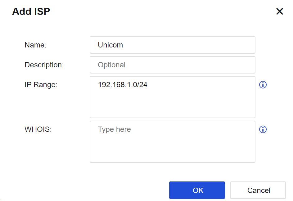
Name: Specify the name of the ISP.
IP Range: Manually set the network IP address range for the ISP.
WHOIS: Set the WHOIS flag mapping to the ISP IP address range. You can identify the addresses of different ISPs according to the flag.
Click ISP Lookup. Then, you can enter the IP address to query its corresponding ISP, as shown in the following figure.
IP Location
To correct faulty IP locations and query IP locations, thus reducing impacts caused by the faulty IP locations, and more accurately displaying attack sources and other information.
IP Location Correction
When you detect that an IP address of the LAN does not belong to the region you specify as the administrator, you can change the region to a correct region where the IP address resides or create a custom IP location.
On the IP Location tab, click Add to create a custom IP address location, as shown in the following figure.
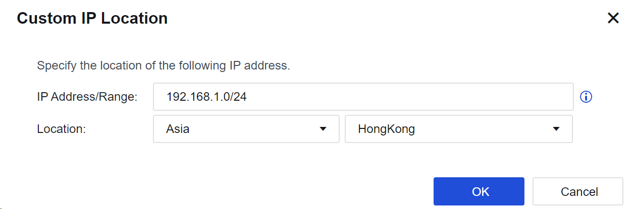
Location Query
When abnormal traffic is detected in the LAN, the administrator can locate the location of the IP through the attribution query and then make corresponding policies.
Click Location Lookup to find the corresponding IP address, as shown in the following figure.
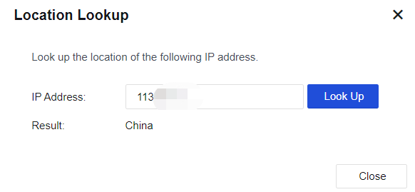
Update IP Address Database
Under the circumstance that the device can access the Internet, the IP address database will be updated in real time. It can also be manually updated to obtain the latest IP address database. If the IP address database is already the latest one, there will be a prompt for not updating during the manual update. Click Yes, as shown in the following figure.
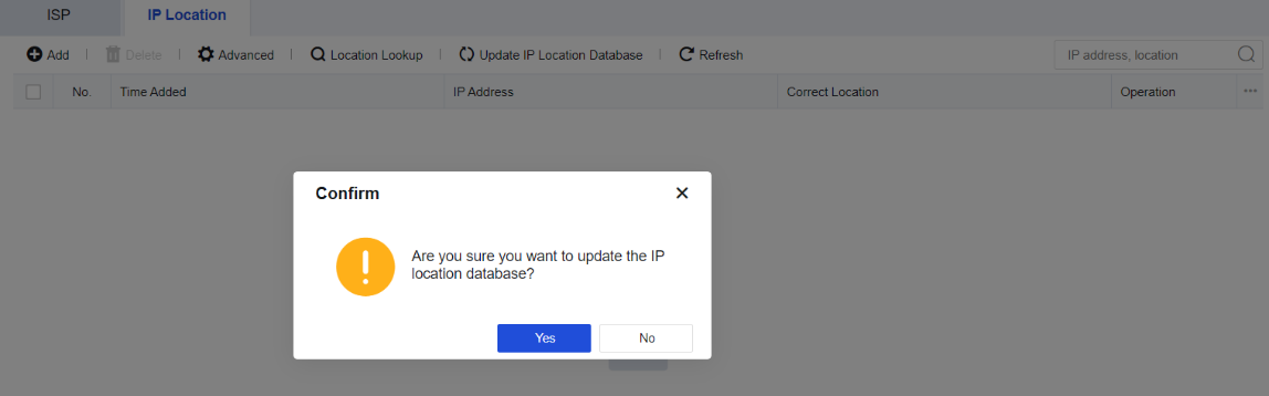
Schedule
To define common time combinations. When configuring Application Control and Bandwidth Channel, you can select the preset time range to define the time when these rules take effect or expire. It includes two tabs: One-Time Schedule and Recurring Schedule.
One-Time Schedule
You can specify the start date and time for a schedule to be executed on the One-Time Schedule tab. The device will launch the schedule within the specified time. This schedule is only executed once on particular dates. For example, you can specify an application control policy with the schedule to prohibit game playing during National Day. After the holiday, games will be released without manual operation.
Navigate to Objects > Schedule and click the One-Time Schedule tab.
On the One-Time Schedule tab, click Add. The Add One-Time Schedule dialog box appears. See the figure below.
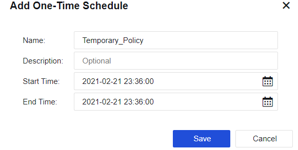
Name: Specify the name of the schedule group.
Start Time: Specify the start date and time of the schedule.
End Time: Specify the end date and time of the schedule.
Recurring Schedule
On the Recurring Schedule tab, you can specify a particular time from Monday to Sunday, during which the device will execute the schedule circularly.
Navigate to Objects > Schedule and click the Recurring Schedule tab.
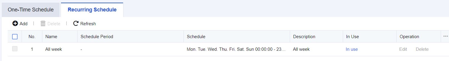
On the Recurring Schedule tab, click Add. The Add Recurring Schedule dialog box appears.
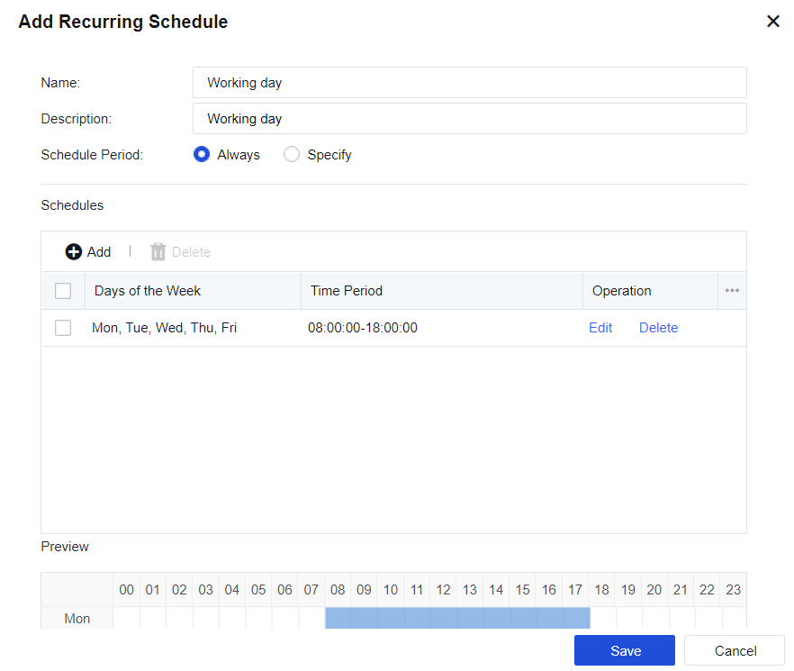
Name: Specify the name of the schedule group.
Description: Specify the description of the schedule group.
Schedule Period: Specify the time range within which the schedule takes effect.
Click Add to set the specific time and time range.
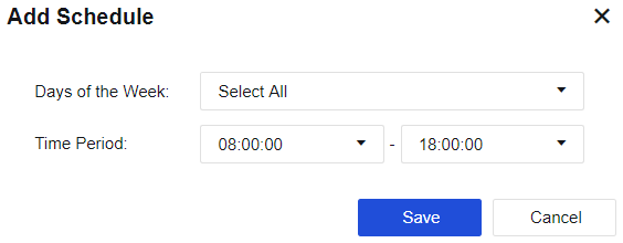
Network
This chapter will introduce the contents and configuration methods of network-related features.
Interfaces
To establish connections between devices in a network and complete data exchange between devices.
Configurations of interfaces vary greatly, depending on the deployment modes. Interface sets each network interface on a device and LAN to which the interface belongs. Physical Interfaces, Subinterfaces, VLAN Interfaces, Aggregate Interfaces, GRE Tunnels, and Link State Propagation are available for setting, as shown in the following figure.
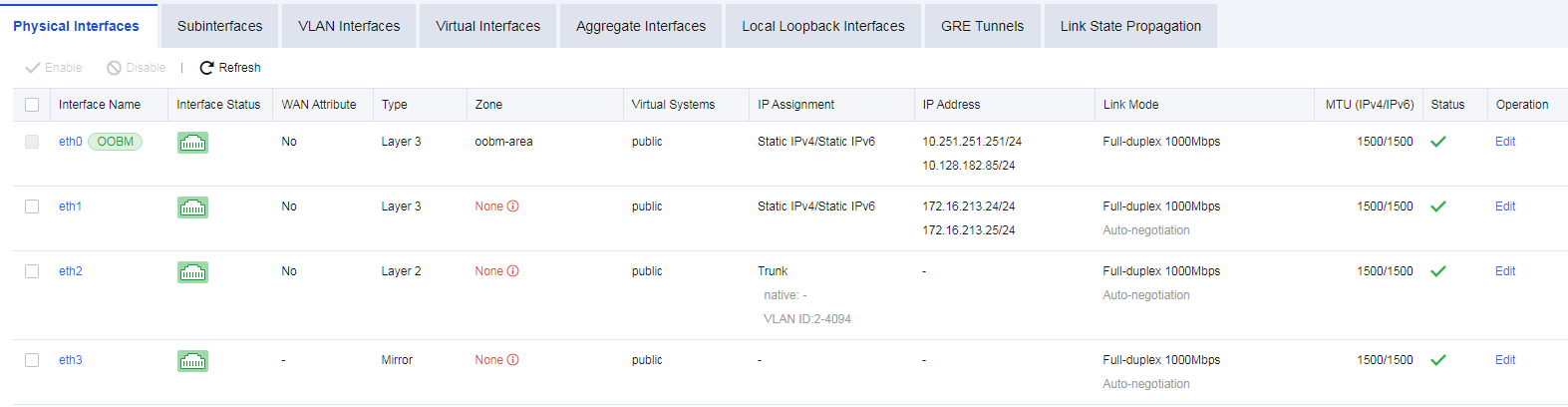
Physical Interfaces
The interfaces on the device panel correspond one to one (for example, eth0 corresponds to the management interface). Physical interfaces cannot be deleted or added. The number of physical interfaces depends on the hardware (a few platforms support expansion). This page shows details of each interface, including Name, description, WAN, interface Type, IP Assignment, Zone, IP Address, dialing status, MTU, Link Mode, PING, network interface status, Link State, etc., as shown in the following figure.
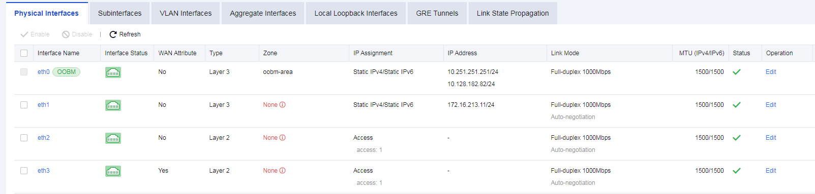
Name: Refers to the name of a network interface. The name of a physical interface cannot be modified.
Interface Status: Indicates the connection status of a network interface. If the connection status is in green, it indicates that the interface is in UP status; if it is in white, it indicates that the interface is in DOWN status.
WAN: Indicates whether a physical interface has WAN attribute(s). Enable this function when traffic control needs to be configured.
PING: Indicates whether it is allowed to enable PING on an interface. You can ping the interface; otherwise, ping is blocked.
Interface Type: Indicates the type of interface. There are four types of interfaces: routing interface, transparent interface, virtual cable interface, and mirror interface.
Zone: Indicates the security zone to which the interface belongs.
IP Assignment: Indicates the type of the obtained IP address of an interface, including PPPoE, static IPv4, DHCP IPv4, static IPv6, and DHCP IPv6.
IP Address: Indicates the IP address configured for an interface.
MTU: Displays the MTU information of an interface. MTU can be configured. MTU range: 68 – 1500.
Link Mode: Indicates the working mode of the physical network card for a network interface and configures the working mode of a physical network card.
Status: Displays the enabled status of an interface.
Operation: Edit interface details.
Edit Physical Interface
Click the interface named eth1 to open the configuration page, as shown in the following figure.
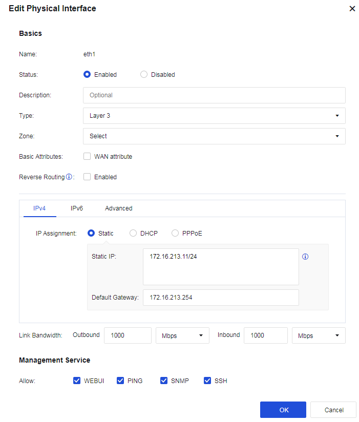
Status: To enable or disable the interface.
Type: Configure the interface mode. It determines the data forwarding function of a device. There are four types:
Layer 3(Routing): If the interface is selected to serve as a routing interface, it indicates that it works in Layer 3 mode, and an IP address must be configured. The interface has the function of routing and forwarding.
Layer 2(Transparent): The transparent interface serves as an ordinary exchange interface, neither requiring the IP address nor supporting routing and forwarding. It forwards data based on the MAC address table.
Virtual Wire: The virtual wire interface is also an ordinary exchange interface that neither requires the IP address nor supports routing and forwarding. It forwards data directly through the paired interface of the virtual cable.
Mirror: The mirror interface connects to a switch with the mirroring function to mirror the data flowing through the switch.
Basic Attributes: Set the interface’s basic attributes and decide whether it is a WAN interface.
Reverse Routing: Specify whether data packets are sent out through the same link they come in. You need to enable this option when there are WAN links of multiple ISPs; otherwise, the service may be inaccessible. This option is automatically enabled once the WAN attribute is selected.
Obtaining an IPv4 address:
Selecting Static IP means that the interface’s IPv4 address and next-hop IP address are specified by manual configuration. To configure routing on the interface, you need to configure a corresponding IP address.
If you’re setting up a dual-device active-standby, please add -HA to the IP/netmask for the out-of-sync IP addresses.
You must fill in the Next-Hop IP field if the WAN box is checked. The default route will not be generated automatically after Next-Hop IP has been filled up.
Selecting DHCP means that the IPv4 IP address and next-hop IP address are automatically obtained using DHCP.
Selecting PPPoE to obtain an IP address by dialing. As ISPs’ IP addresses are changed frequently, adding default route(s) is required.
Obtaining an IPv6 address:
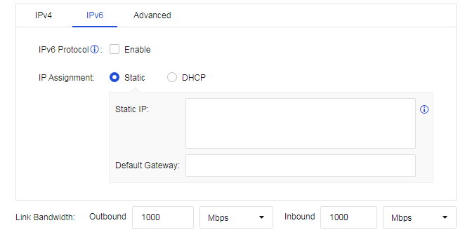
Select Static IP means that the interface’s IPv6 address and next-hop IP address are specified by manual configuration.
Selecting DHCP means that the IPv6 IP address and next-hop IP address are automatically obtained using DHCP.
Advanced: You can set the interface’s link mode, MTU, and MAC address. You can also enable jumbo frame to support 9,000-byte MTU, as shown in the following figure.
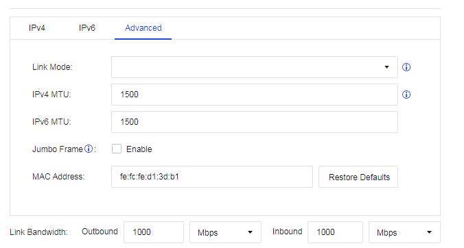
- Link Bandwidth: Set the line bandwidth range of the interface, as shown in the following figure.

- Management Service: Set whether to allow the interface to access devices, such as HTTPS, PING, SSH, and SNMP.

Note:
- Management interface ETH0 is a routing interface whose interface mode cannot be changed.
- Users can add management IP addresses to ETH0. However, the default management IP address 10.251.251.251/24 cannot be deleted. For NGAF8.0.23 or higher versions, implement changes under System > General Settings > Network.
- The IPv4 address of any interface must not lie in the 1.1.1.0/24 segment.
- You cannot simultaneously activate the preemption function in dual-device active-standby mode and link detection.
Subinterfaces
Subinterfaces are multiple logical virtual interfaces configured on one main interface. Subinterfaces depend on the physical interface, share physical layer parameters of their main interface, or be configured with their respective link-layer and network layer parameters. Main interface status change affects the status of subinterfaces. Subinterfaces can work only when the main interface is connected. The device supports creating subinterfaces on a Layer 3 Ethernet interface and a Layer 3 VLAN-Trunk interface. When a Layer 3 Ethernet interface or VLAN-Trunk interface needs to identify VLAN packets, it can be solved by configuring subinterfaces. This way, packets from different VLANs can be forwarded from different subinterfaces, providing users with high flexibility.
Configure on the Network > Interfaces > Subinterface, and click Add to create subinterfaces, as shown in the following figure.
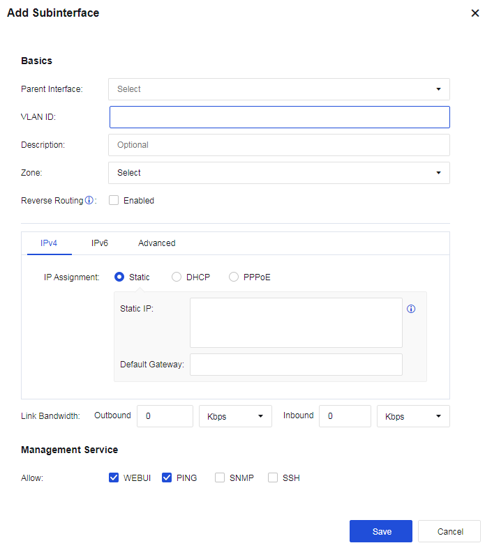
Physical Interfaces: Select the subinterface created on the physical interface.
VLAN ID: The VLAN ID created indicates that the interface supports receiving and sending messages corresponding to the VLAN ID.
Description: Enter the description of the subinterface.
Zone: Select the zone defined for the subinterface.
Reverse Routing: Specify whether data packets are sent out through the same link they come in. You need to enable this option when there are WAN links of multiple ISPs; otherwise, the service may be inaccessible. This option is automatically enabled once WAN Attribute is checked.
MTU in Advanced: Specify the maximum transmission unit of the interface. You can set it in the range of 68-1500.
VLAN Interfaces
When a host on a VLAN needs to communicate with a device operated at the network layer, a VLAN-based logical interface (i.e., a VLAN interface) can be created on the device. The function of the VLAN interface is the same as that of an ordinary Layer 3 physical interface, which can implement various Layer 3 features such as IPv4/IPv6 address configuration. It is used in Layer 2 transparent deployment scenarios to implement communication between VLANs.
To create a new VLAN interface, click Add on the Network > Interfaces > VLAN Interface page, as shown in the following figure.

VLAN ID: Create a virtual interface for a VLAN to achieve Layer 3 intercommunication.
Description: Briefly describe the interface.
Zone: Select the network zone to which the VLAN interface belongs.
Reverse Routing: Specify whether data packets are sent out through the same link they come in. You need to enable this option when there are WAN links of multiple ISPs; otherwise, the service may be inaccessible. This option is automatically enabled once WAN Attribute is checked.
Selecting Static IP means that the interface’s IPv4 address and next-hop IP address are specified by manual configuration.
DHCP: Specify whether the IPv4/IPv6 address and next-hop IP address of the interface are automatically obtained using DHCP.
MTU in Advanced: Specify the maximum transmission unit of the interface. You can set it in the range of 68-1500.
Virtual Interfaces
VSYSs communicate with each other through virtual interfaces.
A virtual interface is a logical interface automatically created for a VSYS upon its creation, which is used by the VSYS to communicate with other VSYSs. The link layer and protocol layer of a virtual interface always remain up. To enable communication between VSYSs through a virtual interface, you must set an IP address for the virtual interface and add it to a security zone so that it can operate properly.
Virtual interface names are defined in vsysif+interface number format. The public system’s virtual interface name is vsysif0. The vsysif interface numbers for other VSYSs start at 1 and are automatically assigned based on the system’s usage of interface numbers.

The following figure shows that virtual interfaces of the public system and VSYSs are connected through virtual links. If the public system and VSYSs are treated as independent devices and virtual interfaces are used for communication between them, you can add the virtual interfaces to security zones and configure routes and policies to enable communication between the public system and each VSYS and between VSYSs.
Aggregate Interfaces
It is a logical interface formed by binding multiple Ethernet physical interfaces, providing more bandwidth, higher link reliability, link load sharing, and other advantages. To create a new aggregate interface, click Add on the Network > Interfaces > Aggregate Interface page, as shown in the following figure.
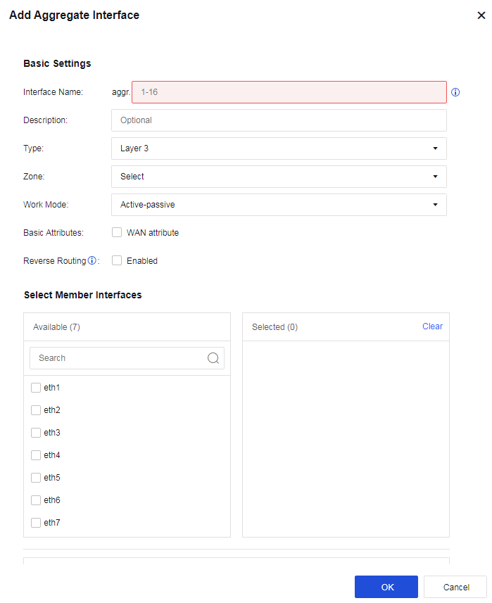
Name: Fill in the serial number of the aggregate interface. Only No. 1-16 can be filled in, i.e., up to 16 aggregate interfaces are supported.
Description: Briefly describe the interface.
Type: Configure the interface mode. It determines the data forwarding function of a device. There are three types.
-
Layer 3: If the interface is selected to serve as a routing interface, it indicates that it works in Layer 3 mode, and an IP address must be configured. The interface has the function of routing and forwarding.
-
Layer 2: The layer 2 interface is an ordinary exchange interface that neither requires the IP address nor supports routing and forwarding. It forwards data based on the MAC address table.
-
Virtual Wire: The virtual wire interface is also an ordinary exchange interface that neither requires the IP address nor supports routing and forwarding. It forwards data directly through the paired interface of the virtual cable.
Work Mode: The working mode the aggregate interface supports, including Load balancing-hash, Load balancing-RR, Active-passive, and LACP.
-
Load balancing-hash: Allocates data packets evenly according to the hash value of the source and destination IP addresses/MAC addresses of data packets.
-
Load balancing-RR: Directly allocate data packets to each interface round-robin.
-
Active-passive: Takes the interface with the largest eth number as the active interface to send and receive packets and the rest as the passive-interface (s) (for example, if eth2 and eth1 are selected, eth2 will serve as the active interface and eth1 will be the passive one).
-
LACP: Standard LACP protocol docking. After selecting the LACP option, three hash strategies are available based on:
a) Source IP and destination IP and source mac destination mac;
b) Source IP and destination IP and source port destination port;
c) Source mac destination mac.
d) It supports both active and passive negotiation as well.
Note:
The aggregate interface does not support Mirror mode.
Local Loopback Interfaces
A local loopback interface of the device is a virtual interface that never fails by default.
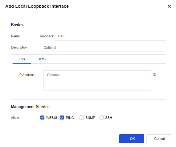
GRE Tunnel
GRE tunnels support GRE over IP, GRE over OSPF, and GRE over IPSec VPN. Click Add to add a GRE tunnel, as shown in the following figure.
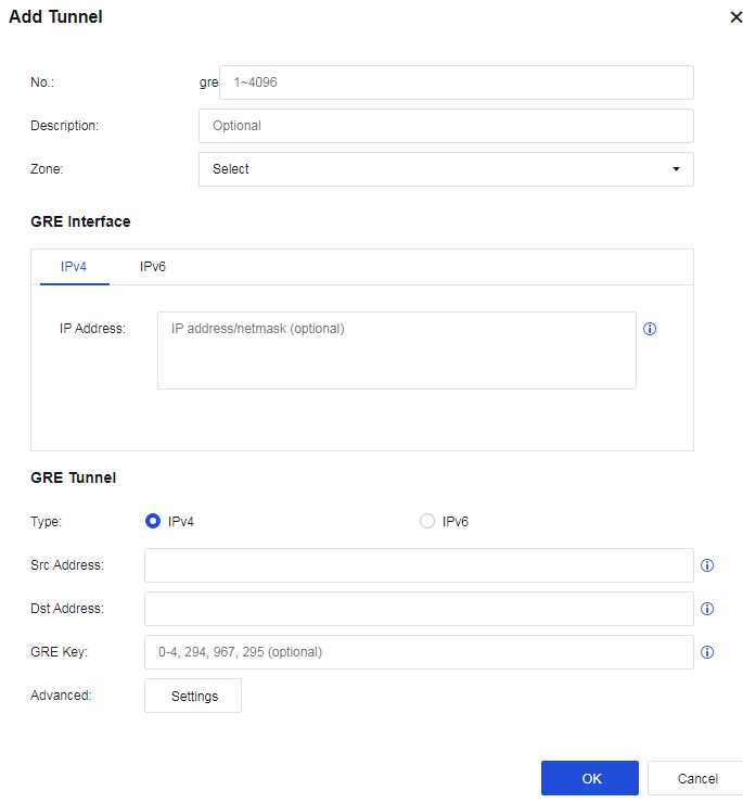
Tunnel No.: The number of the new tunnel port.
Zone: The zone where the outbound interface resides.
IP Address: The IP address of the new tunnel. The network segment where the IP address resides serves as the OSPF running segment.
Type: Specify the tunnel type, which can be IPv4 or IPv6.
Source Address: The actual source address of the WAN route of the outbound interface at the local end.
Destination Address: The actual destination address of the WAN route of the incoming interface at the peer end.
GRE Key: A shared key, which must be consistent at both ends.
Advanced: You can set IPv4 MTU, IPv6 MTU, Message Checksum, and Send Keepalive Message.
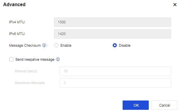
Click Save. The GRE tunnel is successfully set up.
Link State Propagation
Interface Group is used when Network Secure devices work in traffic load balancing mode. The outbound and inbound interfaces of the device responsible for forwarding data are added to the same correlation group, ensuring that all interfaces in the same correlation group are always consistent in status.
For example, when the network cable is disconnected from an interface in the correlation group, the remaining interfaces in the same correlation group are down. Suppose the network cable is connected to the interface again, and the electrical signal is restored. In that case, other interfaces in the same correlation group are recovered to ensure normal switching for traffic load balancing.
Enable Link State Propagation is the master switch to enable the interface correlation function. Check this function and click Add to add an interface group, as shown in the following figure.
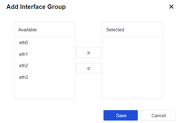
Physical Interface: Select the interfaces to be added to the same interface correlation group. Only physical interfaces can be selected. Multiple interfaces can be selected to add to the same group. Use the Add or Delete buttons to add or delete an interface. You can choose to configure the physical interface of the IPv6 address.
Notice:
If the IP address assigned to an interface is IP/Mask-HA, you cannot set this interface-to-interface correlation.
Zones
To meet the requirements of network architecture security, different services or network segments are classified into different levels of security, and different security zones are defined based on different security levels.
When defining zones, carry out planning according to control requirements. Bind one interface to one zone, or bind several interfaces with the same requirements to one zone. A local Zone is a logical concept that can be divided into Layer 2 zones, Layer 3 zones, and virtual wire zones according to the forwarding types.
-
Layer 2 zones: Only layer 2 interfaces and mirror interfaces can be selected.
-
Layer 3 zones: All layer 3 interfaces can be selected, including routing interfaces, subinterfaces, and VLAN interfaces.
-
Virtual wire zones: Only virtual wire interfaces can be selected.
Click Add to create a zone, as shown in the following figure.
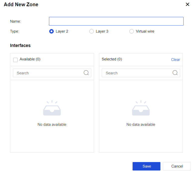
Type: Select Layer 2, Layer 3, or Virtual wire according to different deployment modes.
Routes
Route configuration pages include Static Routes, Policy-Based Routes, OSPF, RIP, BGP, All Routes, and Route Testing. When the device needs to communicate with IP addresses from different network segments, routes are required for data forwarding.
Static Routes
A static route is a special route that needs to be manually configured by the administrator.
When the network structure is relatively simple, the network can work normally only by configuring static routing. Configuring static routes and settings can improve network performance and ensure bandwidth for essential applications.
The disadvantage of static routing is that when a network fails or the networking topology changes, the static routing will not change automatically and must be controlled by the administrator.
Static routes can implement access spanning three layers by devices. The static routes page is shown in the figure below.
Click Add to create a static route. You can create a single or multiple static routes, as shown in the figure below.
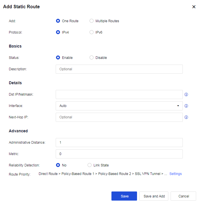
Add: Create One Route or Multiple Routes. If One Route is selected, only one static route can be created. If Multiple Routes are selected, multiple entries of route information are imported in a fixed format.
Protocol: Select IPv4 or IPv6.
Status: Enable or disable this static route.
Dst IP/Netmask: Refers to the destination network segment to be reached and subnet mask.
Next-Hop IP: Refers to the next-hop IP address used to reach the destination network segment. The next-hop IP address cannot be filled with the IP addresses of local network interfaces on the device.
Interface: Select an interface on the device for data forwarding.
Metric: When the destination address is the same, the one with the lower metric value is preferentially selected for forwarding. The lower the metric value, the higher the priority.
Reliability Detection: After being enabled, when the link of the selected interface fails (PING or DNS detection fails), the status of the static route will be set to invalid, and the static route will be deleted from the corresponding route table. When the route is used as a floating static route, this function is recommended to be enabled.
Note:
Reliability Detection must be enabled for the interface(s) selected for the Correlation Interface Link.
Route Priority: Specify the device’s route priorities. Click Settings to change the priority, as shown in the following figure.
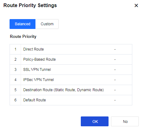
If Multiple Routes are selected, fill in multiple IP addresses according to the format, as shown in the following figure.
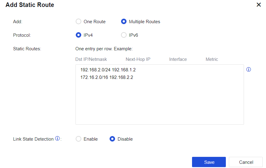
Policy-Based Routes
The operation objects of policy-based routing are data packets. Suppose a routing table has been generated; instead of performing forwarding according to the routing table, the method of its forwarding path is changed according to a certain policy as needed. The primary function is to select the outbound interfaces and lines, according to the source/destination IP addresses, source/destination ports, protocols, and other conditions, when the device has multiple WAN interfaces connecting with multiple WAN lines.
The link fault detection function shall be enabled for the interface/zone. See the figure below.
Source-Based Route
When multiple lines connect to the internet, define the matching conditions according to the source/destination IP addresses, ports, protocols, and applications. Select and specify the line’s outbound interface or next-hop IP address for traffic matched with conditions, such as a multi-ISP routing scenario. Click Add and select Source-Based Route, as shown in the figure below.
Route Type: You can select Source-Based Route or Link Load-Balancing Route.
Protocol: You can select IPv4 or IPv6.
Name: Fill in the corresponding name.
Description: Fill in the description of the route.
Schedule: Specify the effective time range of the policy.
Move To: Put the policy before X, and the matching order is from top to bottom.
Data Packet: Filter and select the corresponding data packet information for matching.
Src Zone: the source zone for matching.
Src Address: the source network object for matching, which is then filtered source IP address. Destination: the destination address for matching. Network Object, ISP, and Country/Region are optional for calling.
Network Object: Call network objects configured according to the actual situation.
ISP: Perform routing according to ISPs. China Telecom, China Unicom, CERNET, and China Mobile are currently supported.
Country/Region: Perform selection by country/region.
Services: the service objects that need to be matched, as shown in the figure below.
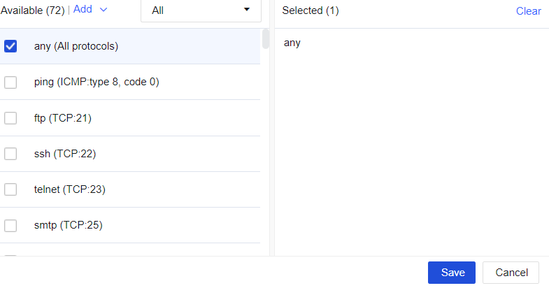
Applications: the applications that need to be matched, as shown in the figure below.
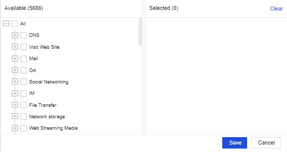
Note:
Applications are hidden by default. Go to System > General Settings > Network and check the Allow associating policy-based routes with applications checkbox.
Interface and Next-Hop IP: Set the next-hop IP address and outbound interface for the next-hop direction of traffic sent to the destination IP address.
Reliability Detection: You can select No or Link State.
Route Priority: Specify the device’s route priorities. You can click Settings to change the priority.
Configuration Case
A user wants to access an online bank with the address 100.100.100.100 using the HTTPS access protocol. The online bank will verify the IP address used for accessing. The online bank will deny access if the source IP address in the same connection is changed. In this case, set a policy-based route and specify that the data accessing the destination IP address is permanently sent out through the line connected to the eth1 interface.
- On the Navigation Menu page, choose Network > Routes > Policy-Based Route, click Add, select Source-based route for Route Type, and select IPV4 for Protocol. Fill in the fields under Basics and Data Packet, as shown below.
- Configure the outbound interface: eth1, as shown in the following figure.
- Click Save to complete the configuration, as shown in the following figure.
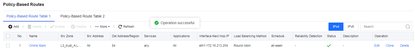
Link Load-Balancing
When a company has multiple lines connecting to the internet, define the matching conditions according to source/destination IP addresses, ports, protocols, and applications, and select policies for the outbound interface to perform dynamic routing to realize effective bandwidth utilization and load balance for these lines.
Click Add and select Link load-balancing, as shown in the figure below.
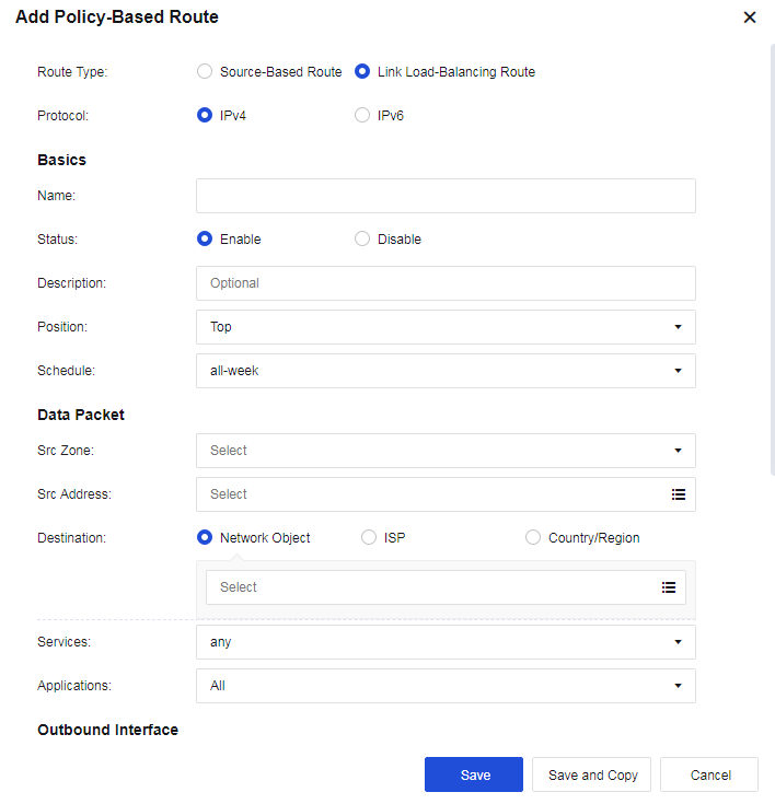
Outbound Interfaces: Select multiple outbound interfaces for the policy and then perform load balancing according to the policy. Click Add to add outbound interfaces, as shown in the figure below.
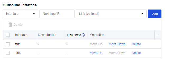
Link State: The line will be regarded as faulty when configuring link detection for an interface, and either PING or DNS detection fails.
Load Balancing Method: Perform traffic load balancing according to the algorithm. There are four algorithms:
-
Round robin: Evenly allocates connections to multiple WAN lines.
-
Bandwidth ratio round robin: Allocates connections according to the ratio of WAN lines bandwidth.
-
Weighted least traffic: Compares the current line traffic to the line bandwidth and selects the line with the minimum ratio to prioritize connecting first.
-
Prefer link at top: It is used in scenarios requiring active and standby lines. All connections are allocated to the first line. If the first line fails, the connection will be switched to the second selected available line.
Configuration Case
A user has 2 WAN lines: China Telecom lines of 2M and 10M. The user wants to realize that when LAN users access public networks, the line with the least traffic is automatically selected.
- Navigate to Network > Routes > Policy-Based Route, and click Add to add link load-balancing routes. The page is as follows.
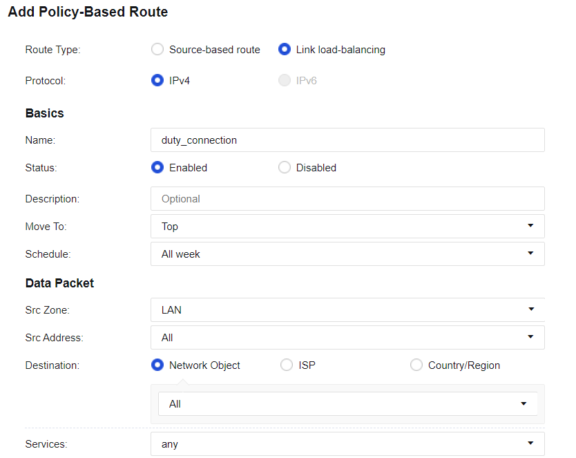
- Configure interfaces, as shown in the following figure.
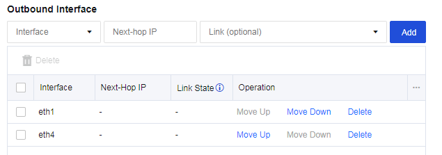
- Select the Load Balancing Method, as shown in the following figure.

- Configure Link State Detection for the corresponding interface. Ensure the link switching can be performed when a link fails, as shown in the following figure.
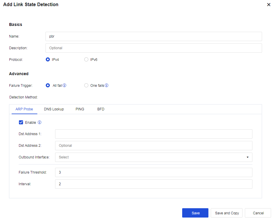
- Check the configuration, as shown in the following figure.

Note:
- To implement load-balancing among multiple WAN lines, Link State Detection must be enabled.
- For link load-balancing, only WAN attribute interfaces can be selected.
- Each WAN line must have a corresponding policy-based route, which can be a source-based route or a link load-balancing one.
Multicast Routes
Network Secure does not forward multicast traffic. For the Network Secure to indicate forwarding multicast traffic, you need to configure multicast routes to forward multicast routes, as shown in the following figure.
Click Add, and the figure below will appear.
Source Address: source address of multicast data.
Multicast Address: the destination address of multicast packets.
Source Interface: the source interface on the host sending the multicast data.
Destination Interface: the interface forwards the multicast traffic(you can select multiple interfaces).
OSPF
Open Shortest Path First (OSPF) is an interior gateway protocol (IGP) for making routing decisions within a single autonomous system (AS). It is an implementation of the link-state routing protocol. OSPF supports load balancing, service type-based path selection, and diverse routing types such as host routing and subnet routing. Network Secure devices support OSPFv2 and OSPFv3.
OSPF
- Add basic configuration. On the OSPF tab, click Add. The Add Basics box appears, as shown in the following figure.
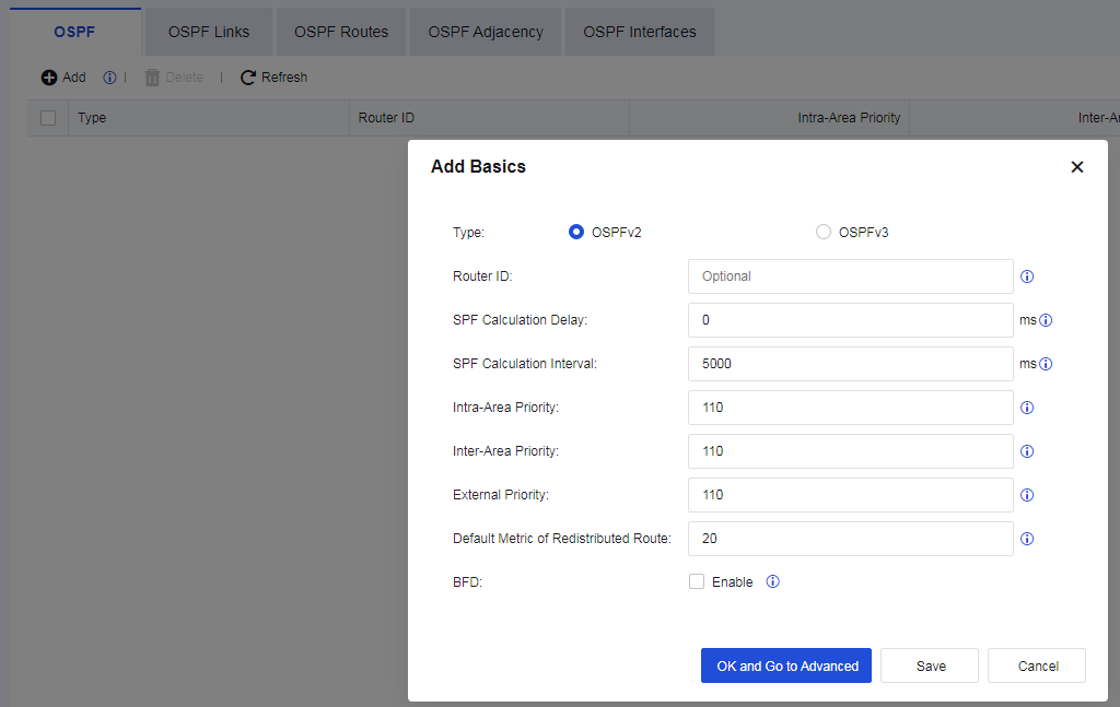
Type: Specify the protocol type, which can be OSPFv2 or OSPFv3.
Router ID: Identify a router in OSPF routing. DR and BDR election is performed based on the numerical value of the router ID.
SPF Calculation Delay: Specify the delay from when OSPF receives changes to when OSPF starts an SPF calculation.
SPF Calculation Interval: Specify the interval between two consecutive SPF calculations.
Intra-Area Priority: Specify the administrative distance for intra-area routes. The value must be an integer from 1 to 255; the default is 110.
Inter-Area Priority: Specify the administrative distance for inter-area routes. The value must be an integer from 1 to 255; the default is 110.
External Priority: Specify the administrative distance for external routes. The value must be an integer from 1 to 255; the default is 110.
Default Metric of Redistributed Route: Specify the default metric of redistributed routes. The default is 20.
BFD: Specify whether to enable global bidirectional forwarding detection (BFD), which can speed up route convergence by eliminating waiting for the neighbor to time out.
- Click OK and Go to Advanced to set Areas. On the Areas page, click Add.
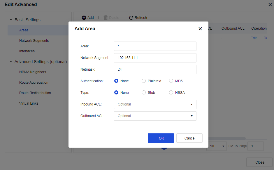
Authentication: You can select None, Plaintext, or MD5.
Type: You can select None, Stub, or NSSA. In stub areas, ABRs are prevented from injecting Type-5 LSAs. This limitation significantly reduces routing table sizes and the volume of routing information exchanged within these areas. Not-So-Stubby Area (NSSA) is a variation of stub areas. In NSSAs, Type-5 LSA injection is prohibited, but Type-7 LSA injection is permitted. When Type-7 LSAs reach the ABR in an NSSA, the ABR converts them to Type-5 LSAs and distributes them to other areas.
Inbound ACL and Outbound ACL: You can select network segments for inbound/outbound access control after setting network segments in Network > Routes > Access Lists.
- Set network segments. On the Network Segments page, click Add, select an Area, and enter the Network Segment to be advertised and its Netmask, as shown in the following figure.
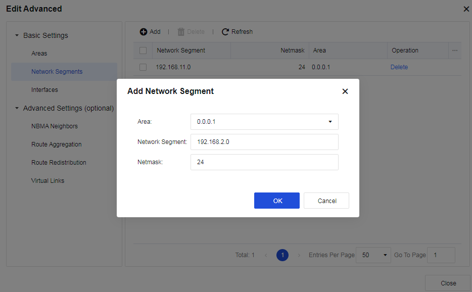
- View interface information after setting network segments. On the Interfaces page, the interface information corresponding to the network segment to be advertised is displayed. You can edit the interface information, as shown in the following figure.
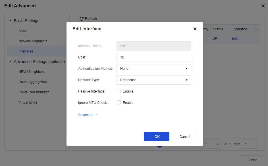
Cost: Specify the link cost of the current interface.
Authentication: Select an authentication method for the interface. The default option is None.
Network Type: Select Broadcast, NBMA, Point-to-MultiPoint (P2MP), or Point-to-Point (P2P).
Passive Interface: When enabled, the interface only receives updates without sending messages.
Ignore MTU Check: Interfaces with inconsistent MTUs can also work as neighbors when enabled.
You can click Advanced to set DR Priority, Transmit Delay, Neighbor Timeout, Hello Packet Interval, and Retransmit Interval, as shown in the following figure.
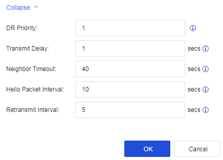
- Configure Advanced Settings (optional). Configure an NBMA Neighbors. NBMA networks are non-broadcast multi-access networks such as ATM and frame relay networks. When you set an NBMA network for an interface, broadcasting Hello packets cannot discover adjacent routers. Instead, you must manually configure the link-local addresses of adjacent routers for probing and establishing neighbors. Subsequent packets are exchanged via unicast. Click Add, as shown in the following figure.
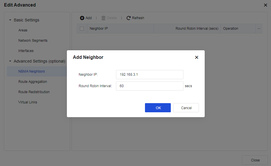
- Configure Route Aggregation. Route aggregation refers to combining routes with the same prefix through the ABR to advertise only one route to other areas. You can add multiple network segments in one area for OSPF to aggregate them. Click Add, as shown in the following figure.
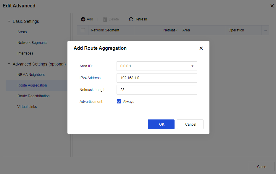
- Configure Route Redistribution. OSPF protocol allows you to introduce and advertise routes from other OSPF processes and routing protocols (Direct Routes, Static Routes, Default Routes, BGP, RIP, and VPN). You can set Metric and Type for the introduced external route. Click Add, as shown in the following figure.
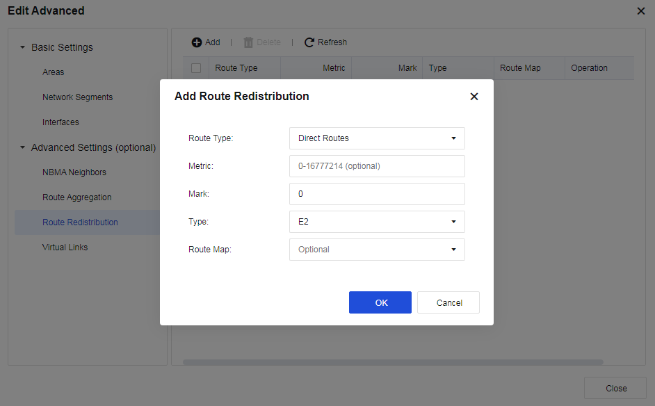
- Configure Virtual Links. Virtual links are used to connect discontinuous backbone areas to ensure their logical continuity. You can configure a virtual link and set the timer parameters. Click Add, as shown in the following figure.
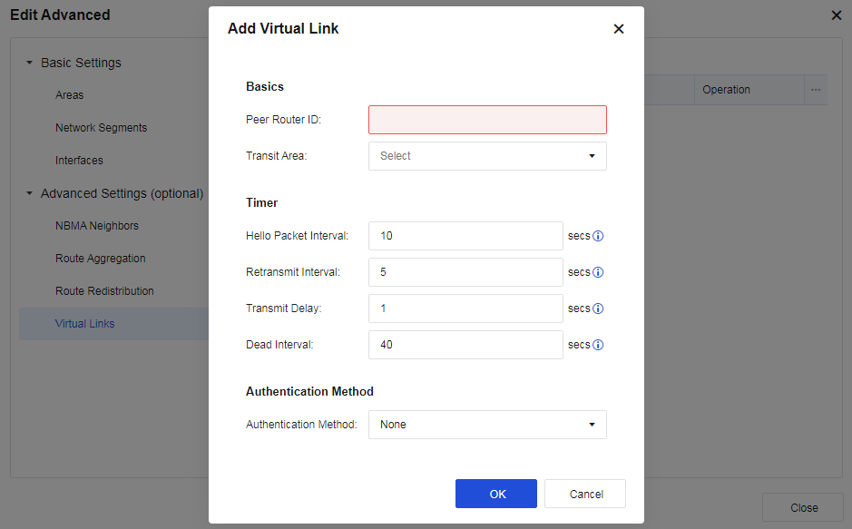
OSPF Links
This tab displays OSPF Links state information, as shown below.
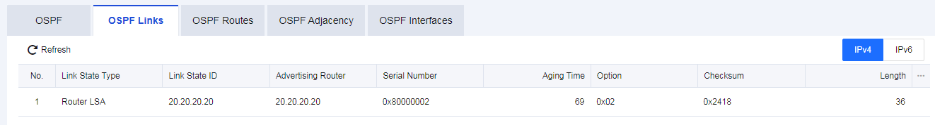
OSPF Routes
This tab displays the OSPF Routes in the network, as shown in the following figure.
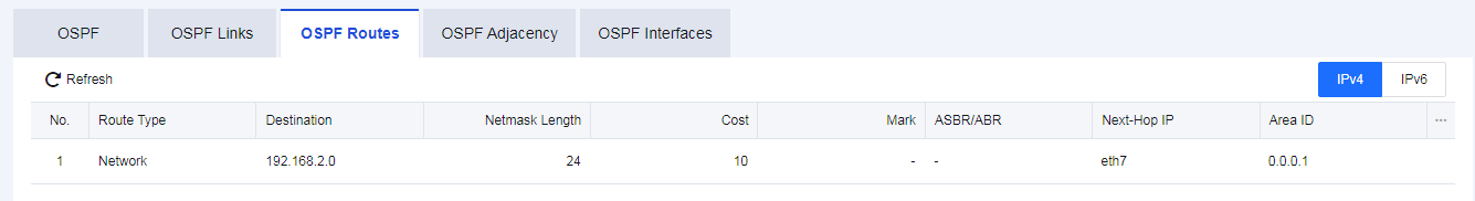
OSPF Adjacency
This tab displays OSPF Adjacency information, as shown in the following figure.
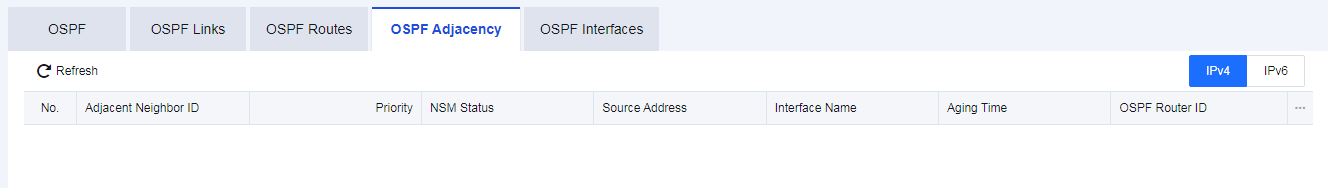
OSPF Interfaces
This tab displays OSPF Interfaces information, as shown in the following figure.
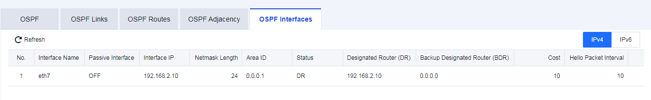
RIP
The RIP uses a distance-vector algorithm. By default, RIP uses a very simple metric system: the distance is defined as the number of links to reach the destination site, taking values from 0 to 16. Infinity is defined as 16. The RIP process uses UDP port 520 to send and receive RIP packets. RIP packets are sent as broadcast packets every 30 seconds, and subsequent packets are sent after a random delay to prevent "broadcast storms". In RIP, if a route does not update within 180 seconds, its metric is set to infinity and the corresponding entry is deleted from the routing table.
RIP is used to enable and set up the RIP dynamic route protocol for Network Secure devices, including network, interface, neighbor, and parameter configurations. Check Enable, as shown in the following figure.
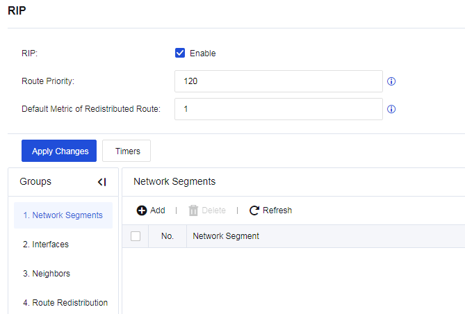
Network Segments
Set the network segment as the RIP segment at the specific interface. Click Add.
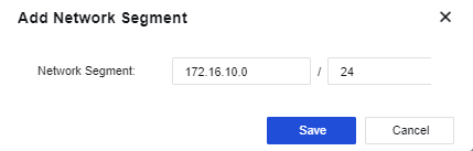
Network Segments: Set the network segment that the device needs to be published. The format is "IP/netmask".
Interfaces
The Interfaces page shows the interface mapping to the network segment where the device is deployed. These interfaces can transmit and receive RIP messages. If network segment information is added under the RIP network, the interface configuration is automatically generated, as shown below.
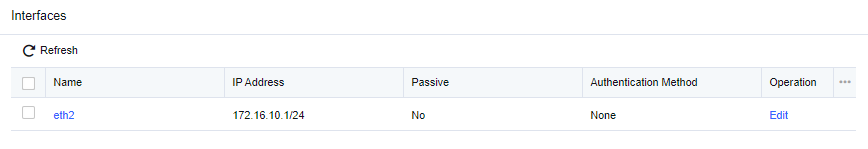
Click an interface under Name to display the following page.
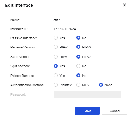
Name: Name of the interface mapping to the network segment where the device is deployed.
Interface IP: IP address of the interface.
Passive Interface: Specify the working state of RIP on the interface. It is set to No by default.
Receive Version: Specify the version of RIP messages received from the interface. When the Receive Version is selected as RIPv2, both RIPv1 and RIPv2 messages can be received.
Send Version: Specify the version of RIP messages sent from the interface. RIPv1 messages are transmitted in broadcast mode; while RIPv2 messages are transmitted in broadcast or multicast (default) mode. When the Send Version is selected as RIPv2, both RIPv1 and RIPv2 messages can be transmitted.
Split horizon: The route learned from an interface must not be transmitted from the same interface. This avoids the route loop to some extent. Split horizon is allowed by default.
Poison Reverse: After Poison Reverse is enabled, the route received from an interface will flood out of this interface. However, the metric of this route is infinite. Poison Reverse is not enabled by default.
Authentication Method: Plaintext, MD5, and None are available for selection. RIPv1 does not support message authentication, while RIPv2 supports plaintext authentication and MD5 authentication.
Password: Set the password for plaintext authentication or MD5 authentication.
Neighbors
To set the IP address of the neighboring device running the RIP, as shown in the following figure.
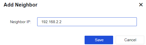
Route Redistribution
Click Route Redistribution, then click Add. The following page will appear.
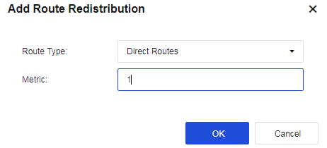
Route Type: Introduce direct routes, static routes, OSPF routes, or BGP into RIP and set the metric for the routes.
Direct Routes: Introduce direct routes into the RIP route as external route information and set the metric value after such routes are introduced. The default metric is 10.
Static Routes: Introduce static routes into the RIP route as external route information and set the metric value after such routes are introduced. The default metric is 20.
OSPF: Introduce OSPF routes into the RIP route as external route information and set the metric value after such routes are introduced. The default metric is 20.
Metric: Default hop count for the introduced routes. If you do not specify the metric for each route type when introducing routes, this metric is used as hop count after such routes are introduced. The default metric is 1.
BGP
To enable and set up the BGP dynamic route protocol for the Network Secure device, including network, neighbor, and parameter configurations. Check the Enablebutton and set the AS Number to enable BGP functions, as shown in the following figure.
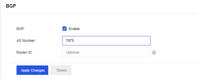
AS Number: Set the AS number for the Network Secure device.
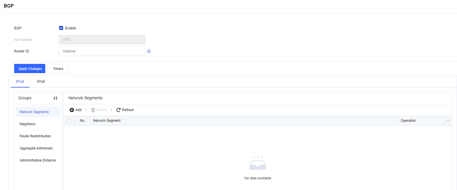
Network Segment
To set the network segment where the device needs to be deployed. Click Add. The following page is displayed.
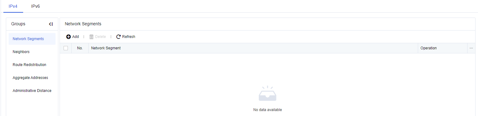
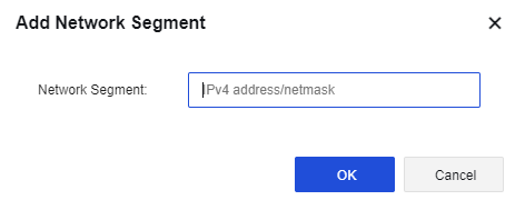
Network Segment: Set the network segment that the device needs to be published. The format is "IP/netmask".
Neighbor
To set the neighbors of BGP. Click Add. The following page is displayed.
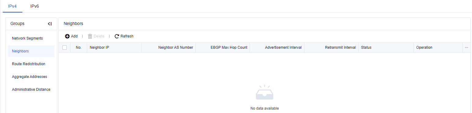
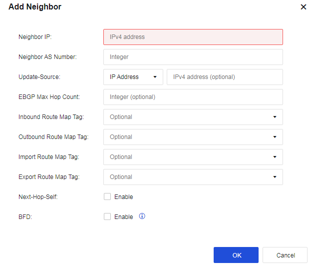
Neighbor IP: Address of BGP’s peer device.
Neighbor AS Number: AS number of the device with which BGP is established.
Update-Source: Updated source address of BGP for the Network Secure device.
EBGP Max Hop Count: Maximum number of EBGP hops for the Network Secure device.
Inbound Route Map Tag: Set the route reception filtering policy based on this routing policy for the peer.
Outbound Route Map Tag: Set the route advertisement filtering policy based on this routing policy for the peer.
Next-Hop Self: By default, when a router advertises routes to IBGP peers/peer groups, it does not use its own address as the next hop. However, sometimes to ensure that IBGP neighbors can find the next hop, you can configure it to use its own address as the next hop.
BFD: When a link failure occurs between the local router and the BGP peer, BFD can rapidly detect the issue to accelerate BGP convergence.
Route Distribution
Click the Route Distribution option, the following page will appear.
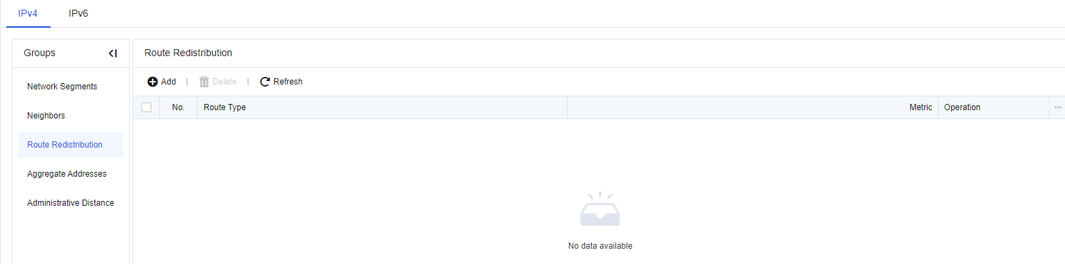

Route type: Select whether to import Direct Routes, Static Routes, OSPF routes, RIP routes and VPN route into BGP routing as external routing information.
Redistribute Direct Route: Select whether to introduce direct routes into the BGP route as external route information and Set the metric value after such routes are introduced.
Redistribute Static Route: Select whether to introduce static routes into the BGP route as external route information and set the metric value after such routes are introduced.
Redistribute OSPF Route: Select whether to introduce direct routes into the BGP route as external route information and set the metric value after such routes are introduced.
Redistribute RIP Route: Select whether to introduce RIP routes into the BGP route as external route information and set the metric value after such routes are introduced.
Redistribute VPN Route: Select whether to introduce VPN routes into the BGP route as external route information and set the metric value after such routes are introduced.
Metric: Set the metric value after the routes are imported.
Note:
The BGP router of Network Secure supports the following public attributes: Route-Map, AS-Path, next hop, origin, local preference, and atomic aggregate.
Aggregate Address
To implement network segment aggregation, click Add to create an aggregate address, as shown in the following figure.
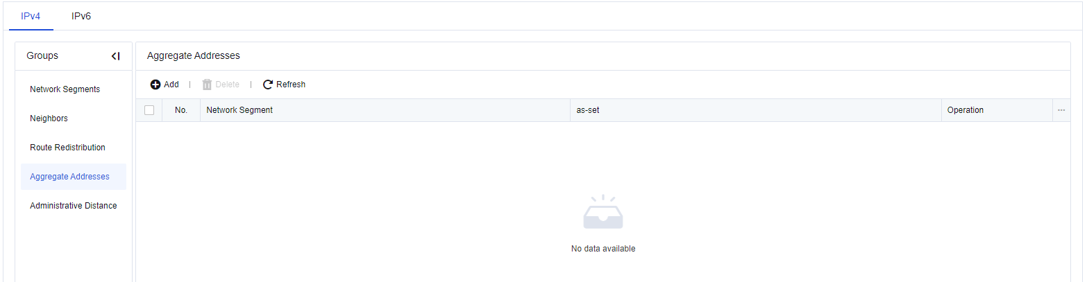
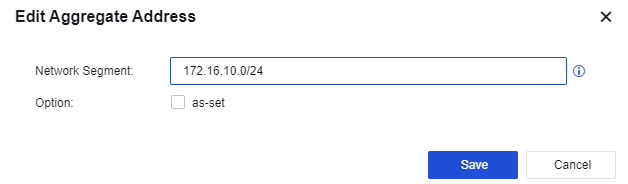
Network Segment: the aggregated IP address network segment.
Option: set whether to retain the original AS number.
Administrative Distance
The administrative distance is used to set the EBGP and IBGP route management distance, as shown in the following figure.
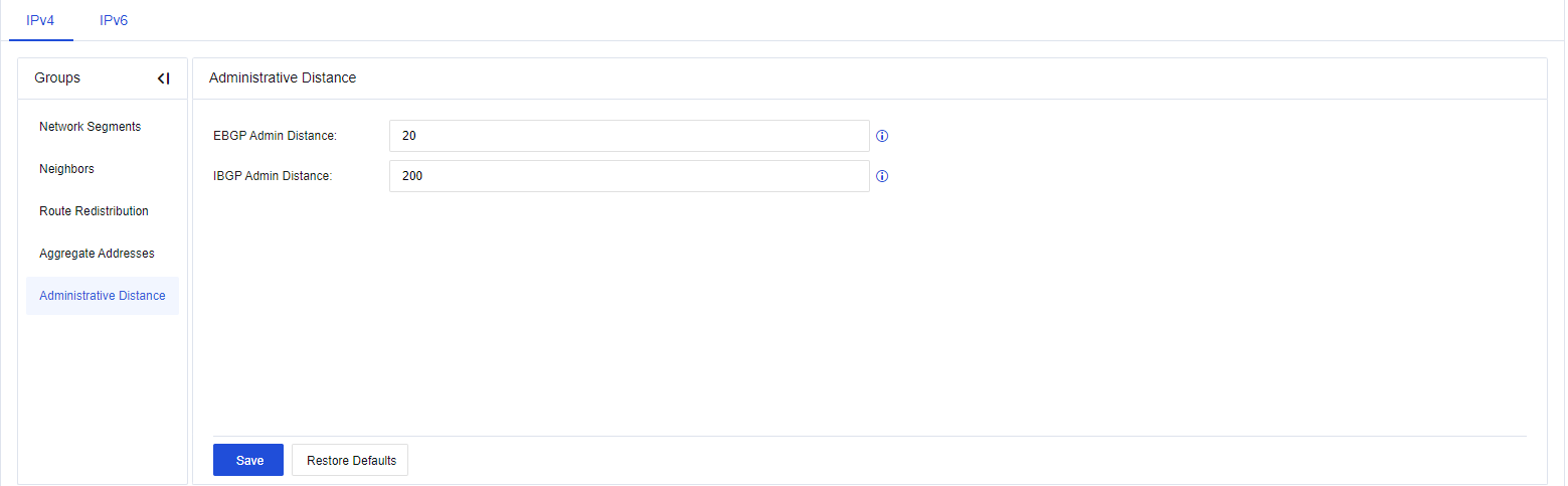
All Routes
View details of all the routes in the device, including direct routes, static routes, and routes learned from dynamic routing protocols, as shown in the following figure.
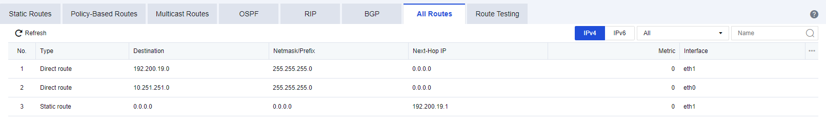
Route Testing
Simulate route matching by entering the IP addresses, protocols, or ports at the front end. The matched routes will be displayed by priority. See the figure below.
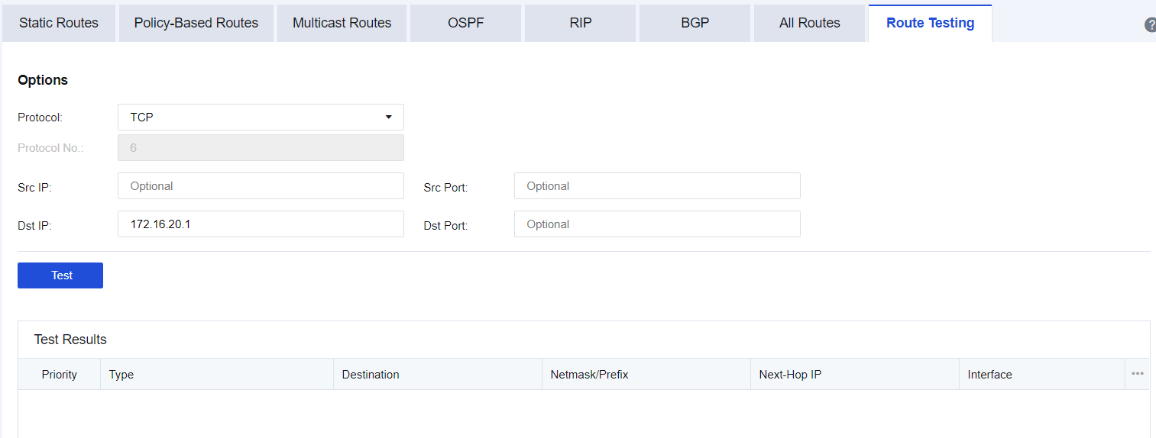
Protocol: Select the protocol for testing, such as TCP, UDP, ICMP, or Others.
Protocol No.: Enter the corresponding protocol number. This field can only be filled in if the option Other is selected in Protocol.
Src IP/Src Port: The source IP address or port to be tested.
Dst IP: The IP address of the destination network segment, which is required.
Dst Port: The port for the destination IP address.
After the testing is completed, the details of this route matching will be listed.
Access Lists
You can allow or deny access to OSPF or BGP routes, as shown in the following figure.
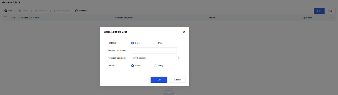
Protocol: Select IPv4 or IPv6.
Access List Name: Enter a number for the access list. The value ranges from 1 to 99.
Action: Specify whether to Allow or Deny access.
Network Segment: Enter a network segment for the access list.
Route Maps
Network Secure redistributes all routing information by default. You can filter redistributed routing information by route map. The route map consists of route matching rules and actions (allow or deny) to be taken after successful matching. If the redistributed routing information hits any route matching rule, Network Secure takes the corresponding action to allow or deny the redistributed routing information.
A route map is a local map created for OSPF and BGP routes. It allows you to adjust the priorities of routes and control their forwarding. On the Route Maps page, click Add. The Add Route Map dialog box appears, as shown in the following figure.
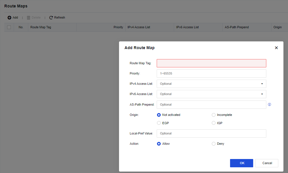
Route Map Tag: Enter a name for the map.
Priority: Enter a priority for the map.
IPv4 Access List: Enter the number of the configured IPv4 access list.
IPv6 Access List: Enter the number of the configured IPv6 access list.
AS-Path Prepend: Enter an AS number.
Origin: Select an original attribute. Not activated is selected by default. Other options include Incomplete, EGP, and IGP.
Local-Pref Value: Enter the priority of the local device.
Action: Specify whether to Allow or Deny the map.
Virtual Wires
To set a group of physical interfaces (e.g. Interface A and Interface B) on the Network Secure device to form a virtual wire group. When packets enter the device from Interface A, all data (except the data whose destination IP address is in the Network Secure device itself) are forwarded from Interface B. The data are sent directly without being searched for in the L2 MAC address table or being checked by the L3 router.
However, the data is still controlled by various security policies. This function enhances Network Secure’s data forwarding efficiency and prevents data forwarding error caused by a messy MAC table.
The configuration of virtual wires is shown in the following figure.
Click Add to add a virtual wire, as shown in the following figure.
Name: Enter the name of the virtual wire.
Description: Enter the description of the virtual wire.
Interface Pair 1: Select a physical interface or aggregate interface with the virtual interface attribute.
Interface Pair 2: Select a physical interface or aggregate interface with the virtual interface attribute.
Notice:
Only the virtual wire type’s physical interface or aggregate interface can be configured as a virtual wire. The virtual interface and virtual wire do not take effect unless being configured simultaneously.
DNS
TCP/IP provides the ability to connect to devices by using IP addresses. However, it is pretty difficult for users to remember the IP address of a particular device. Therefore, a host naming mechanism in the form of strings has been specifically designed, and these host names correspond to IP addresses. A converting and query mechanism is needed between IP addresses and host names, and the system that provides such a mechanism is the Domain Name System (DNS).
DNS Configuration
To set the DNS servers and DNS proxy for the Network Secure device to access the Internet. See the figure below.
Preferred DNS: Set the DNS server address used by the Network Secure device to access the Internet. The Network Secure device uses this DNS address as the first choice for resolution.
Alternate DNS: Set the DNS server address used by the Network Secure device to access the Internet. If the Network Secure device fails to resolve the preferred DNS server address, the alternate DNS server address is selected for resolution.
DNS Proxy: After this function is enabled, the LAN user’s DNS address is set as the interface IP address of the Network Secure device, which forwards the LAN user’s DNS requests to the preferred and alternate DNS servers set for the device. DNS proxy uses port TCP/53. After it is enabled, this port on the firewall can be accessed from all zones. Suppose the firewall is deployed at the network egress. In that case, it is recommended to deny access from public zones to this port by configuring it under Policies > Access Control > Local ACL.
DNS64: Need to enable the DNS proxy before it can be used. DNS64 mainly works in conjunction with NAT64. It mainly converts the A record (IPv4 address) in the DNS query information into an AAAA record (IPv6 address), and then returns the AAAA record to the IPv6 side user.
DNS Transparent Proxy
DNS transparent proxy is an intermediate device (usually the gateway) that intercepts the DNS packets sent from a client through the device itself to the DNS server for parsing according to the relevant settings and returns the responses received to the client. This proxy process is undetectable and completely transparent.
The DNS Transparent Proxy page is for intranet users whose DNS address does not point to the Network Secure device but request to transmit through the Network Secure. The Network Secure’s DNS transparent proxy resolution settings are shown in the following figure.
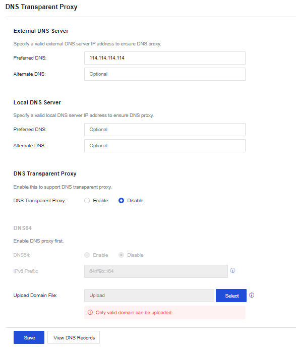
External DNS Server: Set the external DNS server address for the DNS transparent proxy, such as 114.114.114.114. For the DNS address set here, when the DNS Transparent Proxy is enabled, the domain names not uploaded from the Upload Domain File will be subject to proxy resolution using the external DNS address set here.
Local DNS Server: Set the local DNS server address for the DNS transparent proxy. When the DNS Transparent Proxy is enabled, only the domain names uploaded from the Upload Domain File will be subject to proxy resolution using the local DNS address set here.
DNS Transparent Proxy: Set the switch options for enabling or disabling the DNS transparent proxy function.
DNS64: DNS transparent proxy needs to be enabled before it can be used. DNS64 mainly works in conjunction with NAT64. It mainly synthesizes the A record (IPv4 address) in the DNS query information into the AAAA record (IPv6 address) and returns the synthesized AAAA record to the user.
Upload Domain File: Set the domain names that need to be resolved through the local DNS address configured in the Local DNS Server. Under normal circumstances, for access with the domain name of the company’s website, it directly resolves the LAN IP address of the website.
DHCP
The Dynamic Host Configuration Protocol (DHCP) is a network protocol used on local area networks, allowing a server to manage a range of IP addresses so that a client can automatically obtain the IP addresses and subnet masks assigned by the server when logging in to the server. The Network Secure device is deployed in the user environment, serving as a DHCP server to assign corresponding IP addresses to clients.
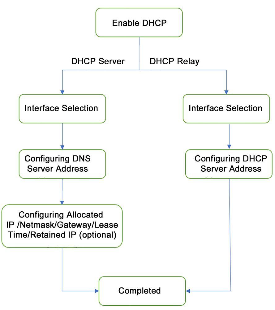
DHCP Servers
Dynamic Host Configuration Protocol (DHCP) is a technique used to dynamically manage and configure IP addresses for users in a centralized manner. Even for smaller networks, DHCP makes the subsequent addition of network devices easier and faster.
DHCP supports two mechanisms for IP address allocation, and network administrators can choose different allocation policies for different hosts according to network requirements.
-
Dynamic allocation: DHCP assigns an IP address to a client for a limited time (which is usually called a lease).
-
This allocation mechanism applies to scenarios where a host needs to be granted temporary access to a network or where the number of free addresses is less than the total number of network hosts and the hosts do not need to be permanently connected to the network.
-
Static allocation: a network administrator assigns a permanent IP address to the specified host using DHCP.
-
Compared with the manual static configuration of IP addresses, the static allocation using DHCP avoids errors generated during manual configuration and facilitates unified maintenance and management by administrators.
The Network Secure device serves as a DHCP server and provides a client with an IP address. Navigate to Network > DHCP > DHCP Options, click Add to enter the Add DHCP Service page and select Service Type, as shown in the following figure.
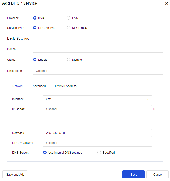
Network
Configure network details of DHCP.
Interface: Show all route interfaces, sub-interfaces, and VLAN interfaces on the device. You can set IP addresses allocated through these interfaces separately.
IP Range: Select the range of the assigned IP addresses. If no data is filled in, the IP addresses assigned to the interface will be used by default.
Netmask: The netmask of the assigned IP address.
DHCP Gateway: Enter the DHCP gateway address. If no data is filled in, the interface address will be used as the gateway.
DNS Server: Set the DNS address assigned to the client.
Advanced
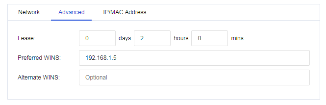
Lease: Set the lease for the IP address assigned by the DHCP server.
Preferred WINS: Configure the preferred WINS server address.
Alternate WINS: Configure the alternate WINS server address.
Reserved IP/MAC Address
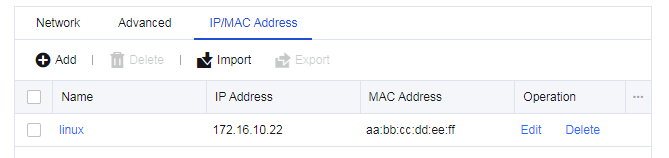
Set the IP addresses that need to be reserved. Click Add to create an IP address to be reserved.
Configuration Case
The LAN interface eth2 on a user’s Network Secure device is connected to a LAN segment. The user requests that the Network Secure device automatically assign the IP address range of 172.16.10.100-172.16.10.199 to users in a conference room for accessing the Internet, and the manager’s computer is permanently assigned with the IP address 172.16.10.150.
- Add a new DHCP server. Select the interface eth1 from the interface list for the DHCP configuration. Configure the IP range and DNS network parameters, as shown in the following figure.
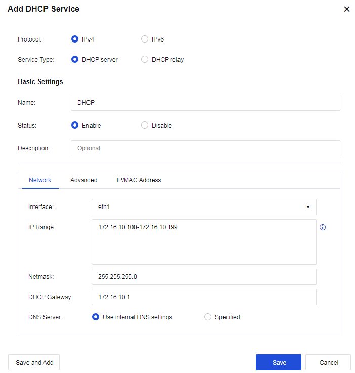
- (Optional) Set the Lease, i.e., the lease issued by the DHCP server, as shown in the following figure.
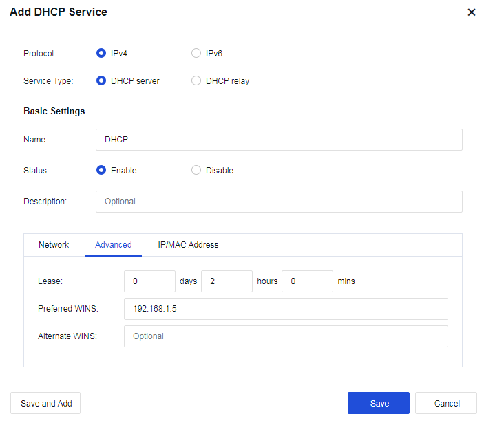
- Set reserved IP Addresses. Click Add to set a reserved IP address, i.e., assign a permanent IP address to the corresponding computer according to its MAC address.
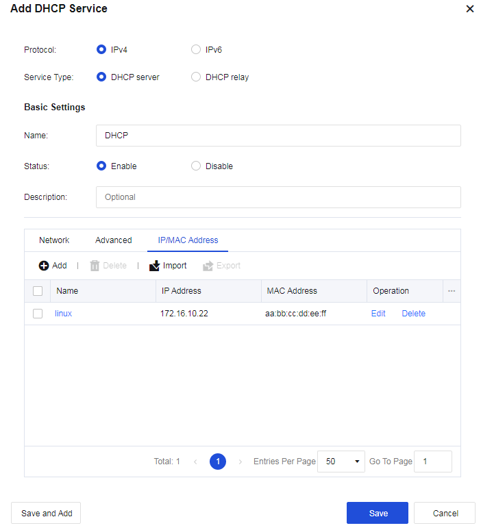
- View the DHCP operation status and the DHCP assignment status.

DHCP Relay
The DHCP Relay function is used in the application scenarios where the IP addresses of the DHCP server and DHCP client reside in different network segments. Select DHCP relay to display the page as follows.
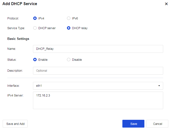
Interface: Select the interface used to receive request packets sent from the DHCP client.
IPv4 Server: Configure the address of the DHCP server.
DHCP Status
The DHCP Status page displays DHCP lease details after the client successfully obtains an IP address through DHCP, as shown in the following figure.
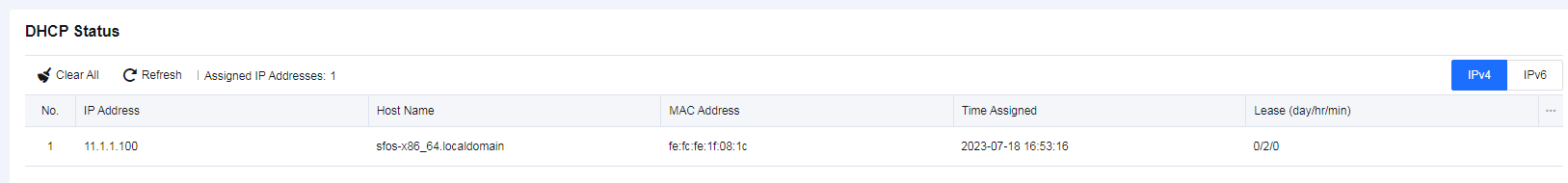
ARP
ARP is known as Address Resolution Protocol. ARP is a mandatory protocol required for all Ethernet devices and implements dynamic mapping of Layer 3 IP addresses to Layer 2 MAC addresses.
ARP resolves IP addresses into MAC addresses. ARP table entries can be divided into dynamic and static entries. In addition, ARP has extended application functions, including proxy ARP, ARP spoofing protection, etc.
ARP Table
ARP Table is used to set static binding IP/MAC entries for the device. Click Add to add a new static ARP entry, as shown in the following figure.
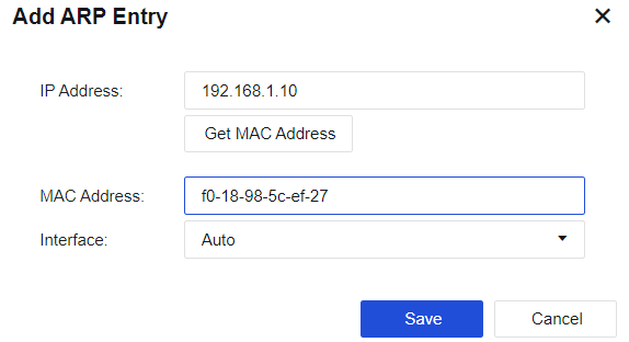
IP Address: Set the destination IP address of the static ARP entry that needs to be bound. The MAC address can be automatically filled in by clicking Get MAC Address.
MAC Address: Set the destination MAC address of the static ARP entry that needs to be bound.
Interface: Set the device interface that resides in the same network segment with the bound IP address.
ARP Proxy
ARP proxy is also called routing proxy ARP. When a host is not configured with a default gateway address (that is, it does not know how to connect to the intermediary system of the network), it can send an ARP request (requesting the MAC address of the destination host). After receiving such a request, the device of which the proxy ARP function is enabled offers its own MAC address as a response to the ARP request. In this way, internal hosts on different physical networks but with the same network number can communicate with each other normally.
Check Enable ARP proxy to enable the ARP proxy function. Click Add to create an ARP proxy, as shown in the following figure.
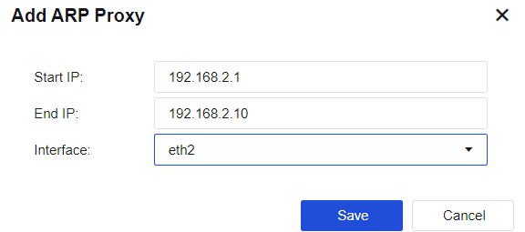
Start/End IP: Enter the IP addresses for which proxy is required.
Interface: Response to the ARP requests received via this interface.
Notice:
- The specified interface on which the ARP proxy should be enabled must be a routing interface.
- The configured IP network segment should not conflict with other network segments for the Network Secure.
- Configuration errors will cause ARP conflicts between the corresponding IP addresses, resulting in network turbulence.
ARP Spoofing Protection
ARP spoofing is a common LAN virus. A PC infected with the virus sends broadcast packets with ARP spoofing to the LAN from time to time, interfering and damaging the normal communication among LAN machines. In severe cases, the entire network will be disrupted. The device protects its ARP cache and thus achieves its immunity by rejecting ARP requests or replies with attack signatures.
If a user of the device who is subject to access control has a bound IP/MAC address, the device will perform ARP spoofing protection based on the bound IP/MAC address.
Check Enable to enable ARP Spoofing Protection, and the configuration page is shown below.
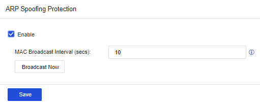
MAC Broadcast Interval (secs): Set the interval for broadcasting the MAC address.
Advanced Networking
TCP MSS
TCP MSS (Maximum Segment Size): The maximum size of the data segment of a TCP packet can be transmitted at a time. For some data that meet certain conditions, Network Secure supports changing the TCP MSS values of such data packets. This function is used to adapt the device to a more complicated network environment. It is advised to enable it when necessary.
Navigate to Network > Advanced > TCP MSS, check Enable to enable TCP MSS configuration, and click Add to add a rule.

Name: Set the rule name.
Description: Set the description of the rule.
MSS: Set the TCP MSS value that needs to be specified.
Src Address/Src Port: Set the source IP group and source port, and specify the source conditions that match this rule.
Dst Address/Dst Port: Set the destination IP group and destination port, and specify the destination conditions matching this rule.
Optical Bypass Module
Network Secure device supports the optical bypass module, which must be used with an optical bypass switch. Check the Enable external optical bypass module checkbox to enable optical bypass. The configuration page is shown in the figure below.
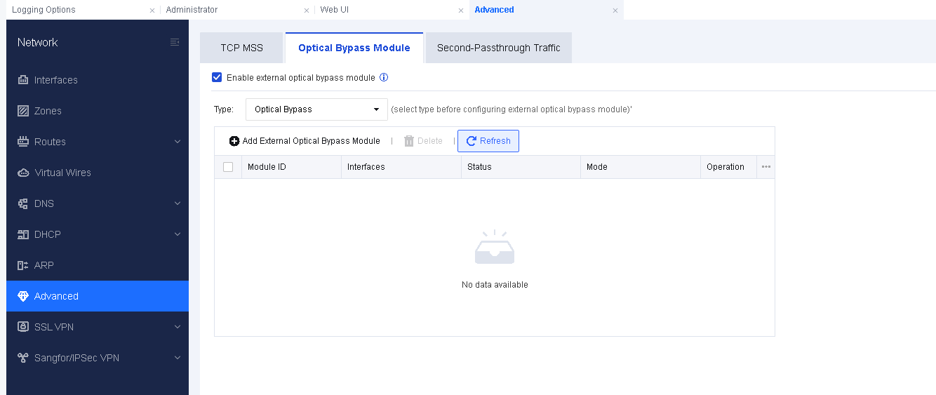
Type: Currently, only domestic optical bypass modules are supported. Please note that optical bypass and HA cannot be enabled at the same time.
Click Add External Optical Bypass Module and configure the corresponding optical module interfaces.
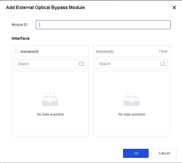
Second-Passthrough Traffic
It is used when a data packet passes through the same Network Secure device many times. The Network Secure device sets the data packet to ensure that the security function works and does not repeatedly check the packet.
Check Enable to enable the second-passthrough function, and then click Add to add a record.
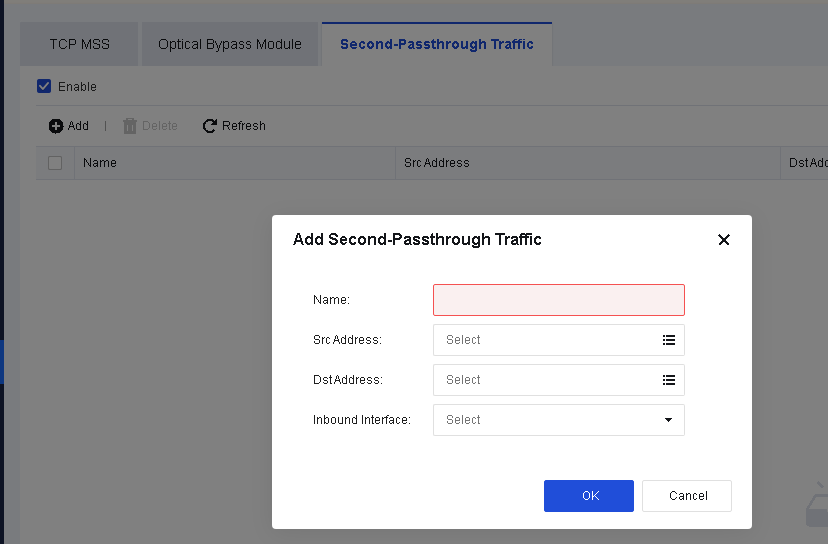
Src Address: Specify the source IP address of the packet. Suppose a data stream passes through "bridge 1" (composed of eth1 and eth2 of Network Secure) and "bridge 2" (composed of eth3 and eth4), and the current security protection policy is configured in the LAN/WAN zone of "bridge 2". In that case, you need to set the source IP address of the packet passing through "bridge 1" here.
Dst Address: Specify the destination IP address of the packet. Suppose a data stream passes through "bridge 1" (composed of eth1 and eth2 of Network Secure) and "bridge 2" (composed of eth3 and eth4), and the current security protection policy is configured in the LAN/WAN zone of "bridge 2". In that case, you need to set the destination IP address of the packet passing through "bridge 1" here.
Inbound Interface: Specify the inbound interface for the packet. Suppose a data stream passes through "bridge 1" (composed of eth1 and eth2 of Network Secure) and "bridge 2" (composed of eth3 and eth4), and the current security protection policy is configured in the LAN/WAN zone of "bridge 2". In that case, you need to set the inbound interface for the packet passing through "bridge 1" here.
Notice:
- Second-passthrough requires a permit for the traffic passing through both inbound and outbound paths.
- Similar to bypass/whitelist, second-passthrough can enable the traffic to pass through without being intercepted.
Configuration Case
The network environment of a company is shown in the figure below. The Network Secure device is deployed at the front end of a server to protect against internal and external attacks. The Network Secure device is deployed in a virtual network with 1 and 2 serving as a pair of virtual lines, and 3 and 4 serving as a pair of virtual lines. When an Internet terminal PC (100.100.100.1) accesses a server (172.16.10.1), it cannot open the page normally. The troubleshooting result reveals that the session abnormality occurred since the traffic passed through the Network Secure twice. Therefore, a second-passthrough needs to be enabled to avoid this issue.
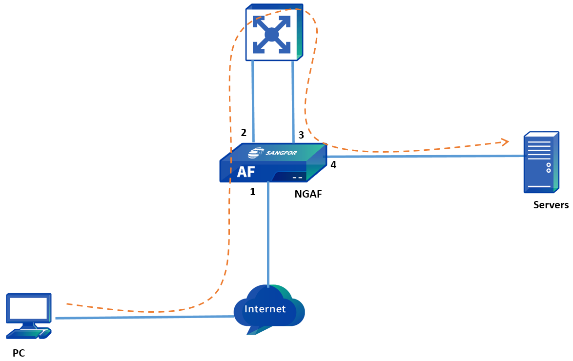
- Check Enable to enable second-passthrough and click Add to create second-passthrough traffic. See the figure below.
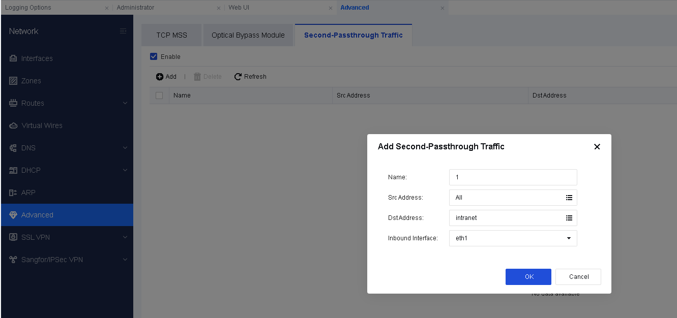
- Second-passthrough needs to be configured for both inbound and outbound traffic. The configuration results are shown in the following figure.
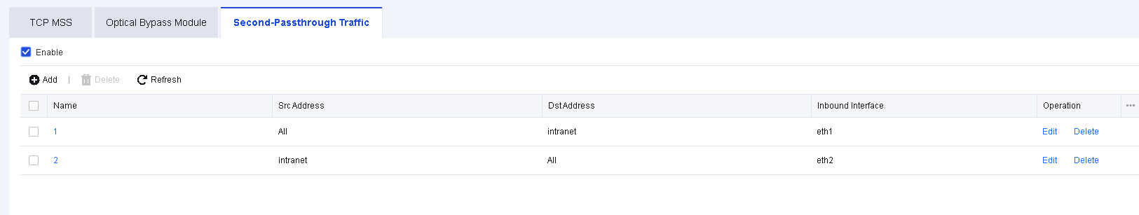
- The Internet terminal PC (100.100.100.1) accesses the server (172.16.10.1) again and can open the page normally.
SSL VPN
Online Users
The Online Users page can view information of the online users, such as the number of users connecting to the SSL VPN, the time when these online users connected, the amount of received/sent bytes, and the outbound inbound speed. The administrator can disconnect or disable any of these online users. The Online Users page is as shown below:
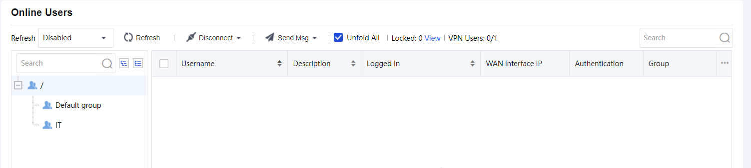
The Online Users page includes the following contents:
Refresh: Specify the time interval to automatically refresh this page, or click the Refresh button to refresh the page manually and immediately.
Disconnect: Click it and select to disconnect, or disconnect and disable the selected user(s), as shown below:
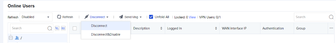
If Disconnect is selected, the selected user will be forced to disconnect from the SSL VPN.
If Disconnect&Disable is selected and the OK button is clicked, the selected user will be forced to disconnect from the SSL VPN. After that, the users will be prohibited from logging in again until it is unlocked.
Click View to open the Locked users page as below:
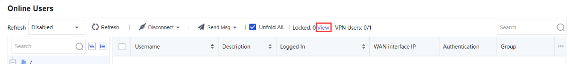
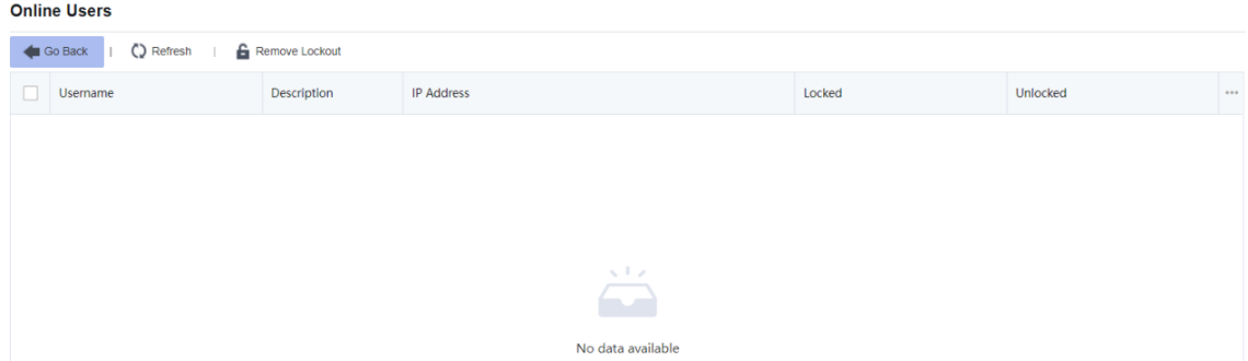
Use Remove Lockout to remove the users from the list. Click Go Back to go to the Online Users page.
Deployment
This page shows the deployment of the SSL VPN in the Network Secure device. There are two types of deployment mode as follows:
Gateway Mode:
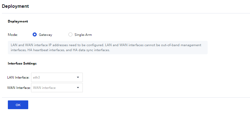
Single-Arm:
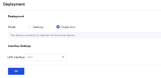
Interface Settings:
If the Gateway mode is selected, the LAN interface and WAN interface need to be configured. For Single-Arm mode, configure only the LAN interface.
Local Users
Users and groups are managed in a hierarchic structure. Users with similar attributes could be classified into a group further included in another higher-level user group. This kind of management is similar to and compatible with the interior organization structure of an enterprise, facilitating the management of VPN users. The Local Users page is shown below:
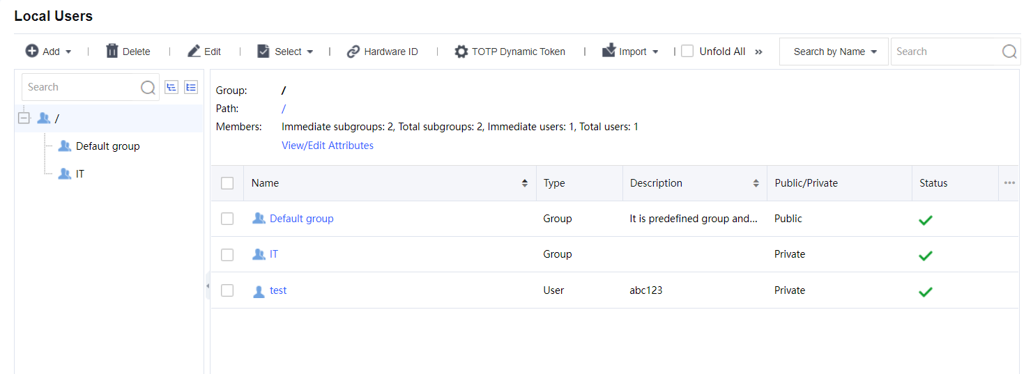
In the left pane, there is a tree of user groups. Click a group name, and that group’s subgroups and direct users will be seen in the right pane, with group information (Group, Path, Members) displaying above the right pane.
To search for a group, enter the keyword of the group name into the search box in the left pane and click the magnifier icon. The group will be highlighted in bold if found.
To see all direct and indirect users of the selected group, click Unfold All.
To delete the selected user or group, click Delete.
To choose the desired entries, click Select > User or Group > On Current Page or On All Pages.
To deselect entries, click Select > Deselect.
To edit the attributes of a user or group, select the user or group and click Edit to enter the Edit User or Edit User Group page.
Adding Group
- Click Add > Group to enter the Add User Group page, as shown in the figure below:
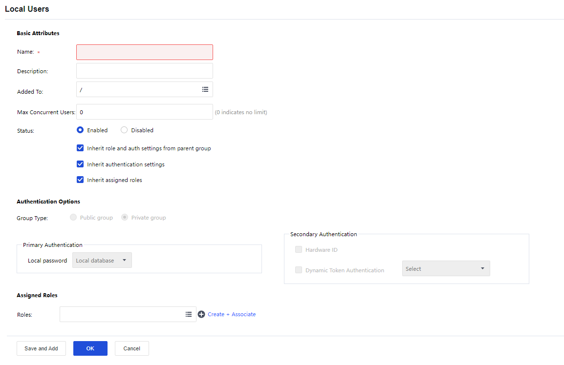
- Configure the Basic Attributes of the user group. The following are the basic attributes:
Name: Enter a name for this user group. This field is required.
Description: Enter a brief description for this user group.
Added To: Select the user group to which this user group is added.
Max Concurrent Users: Indicate the maximum number of users in this group that can concurrently access SSL VPN.
Status: Indicate whether this user group is enabled or not. Select Enabled to enable this group; otherwise, select Disabled.
Inherit role and auth settings from parent group: Select the checkbox next to it, and this user group will inherit the attributes such as the roles and authentication settings.
Inherit authentication settings: Select the checkbox next to it, and this user group will inherit the authentication settings of its parent group.
Inherit assigned roles: Select the checkbox next to it, and the current user group will inherit the assigned roles of its parent group.
- Configure Authentication Options:
Group Type: Specify the type of this user group. Public group or Private group.
Public group: Indicate that multiple users can use any user account in this group to log in to the SSL VPN concurrently.
Private group: Indicate that multiple users who log in to the SSL VPN concurrently can use none of the user accounts. If a second user uses a user account to connect to SSL VPN, the previous user will be forced to log out.
Primary Authentication: Indicate the authentication method(s) that is (are) first applied to verify users when they log in to the SSL VPN. If any secondary authentication method is selected, primary authentication will be followed by secondary authentication when the users log in to the SSL VPN. By default is a Local password.
Local password: The connecting users need to pass local password-based authentication using the SSL VPN account in this user group.
Secondary Authentication: Secondary authentication is an optional and supplementary authentication method. Select it to require the connecting users to submit the corresponding credentials after passing the primary authentication(s), enhancing the security of SSL VPN access.
Hardware ID: This is the unique identifier of a client-end computer. Each computer is composed of some hardware components, such as NIC, hard disk, etc., which are unquestionably identified by their features that cannot be forged. SSL VPN client software can extract the features of some terminal hardware components and generate the hardware ID consequently. This hardware ID should be submitted to the Sangfor device and bound to the corresponding user account. Once the administrator approves the submitted hardware ID, the user will be able to pass hardware ID-based authentication when accessing SSL VPN through a specified terminal(s). This authentication method helps to eliminate potential unauthorized access. As mentioned above, multiple users could use the same user account (public user account) to access SSL VPN concurrently. It is reasonable that a user account may bind to more than one hardware ID. That also means an end-user can use one account to log in to SSL VPN through different endpoints, as long as the user account is binding to the hardware IDs submitted by the user from those endpoints.
- Assign Roles to a user group.
Click the Roles field to enter the Assigned Roles page, as shown below:
Click Add to enter the Select Role page, as shown below:
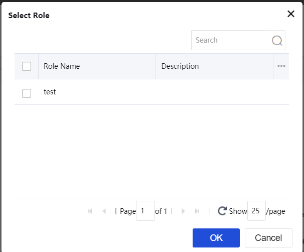
Select the checkbox next to the desired roles and click the OK button. The roles are added to the Assigned Roles page.
Click the OK button and name the assigned roles filled in the Roles field.
If the desired role is not found in the list, click Create + Associate to create a new role and associate with the user group. (The procedures of creating a role are the same as that in the Roles Adding section).
To remove a role from the list, select the role and click Delete.
To edit a role, select the role and click Edit.
Adding User
- Click Add and select User to enter the Add User page, as shown in the figure below:
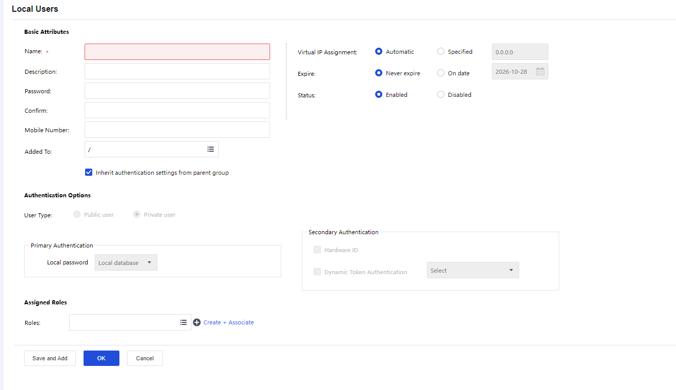
- Configure the Basic Attributes of the user. The following are the basic attributes:
Name: Enter a name for this user. This field is required.
Description: Enter a brief description for this user.
Password: Enter the password of this user account.
Mobile Number: Enter the mobile phone number of the user.
Added To: Specify to which user group this user is added.
Inherit authentication settings from parent group: If selected, the current user will inherit its parent group’s policy set and authentication settings. If not selected, the authentication settings and policy set could differ from those of its parent group.
Virtual IP Assignment: To set the way users get virtual IP.
- Configure the valid time of the user account.
Expire indicates the date on which this user account will get invalid. If Never expire is selected, the user account will always be valid. If the On date is selected, select the date as the expiry date.
-
Configure the Status of the user account. This user account will be enabled (valid) if the Enabled is selected or disabled (invalid) if Disabled is selected.
-
Configure Authentication Options.
Public user: Indicate that multiple users can use the user account to access SSL VPN concurrently.
Private user: Indicate that only one user can use the user account to log in to the SSL VPN at a time. If a second user uses this user account to connect to SSL VPN, the previous user will be forced to log out.
Primary Authentication: Indicate the authentication method(s) that is (are) first applied to verify users when they login to the SSL VPN. If any secondary authentication method is selected, primary authentication will be followed by secondary authentication when the users log in to the SSL VPN. By default, it is a Local password.
Local password: The connecting users need to pass local password-based authentication using the SSL VPN account in this user group.
Secondary Authentication: Secondary authentication is an optional and supplementary authentication method. Select it to require the connecting users to submit the corresponding credentials after passing the primary authentication(s), enhancing security in SSL VPN access.
Hardware ID: This is the unique identifier of a client-end computer. Each computer comprises some hardware components, such as NIC, hard disk, etc., which are unquestionably identified by their features that cannot be forged. SSL VPN client software can extract the features of some terminal hardware components and consequently generate the hardware ID. This hardware ID should be submitted to the Sangfor device and bound to the corresponding user account. Once the administrator approves the submitted hardware ID, the user can pass hardware ID-based authentication when accessing SSL VPN through a specified terminal(s). This authentication method helps to eliminate potential unauthorized access. As mentioned above, multiple users could use the same user account (public user account) to access SSL VPN concurrently. It is reasonable that a user account may bind to more than one hardware ID. That also means an end-user can use one account to log in to SSL VPN through different endpoints, as long as the user account is binding to the hardware IDs submitted by the user from those endpoints.
- Assign Roles to a user group.
Click the Roles field to enter the Assigned Roles page, as shown below:
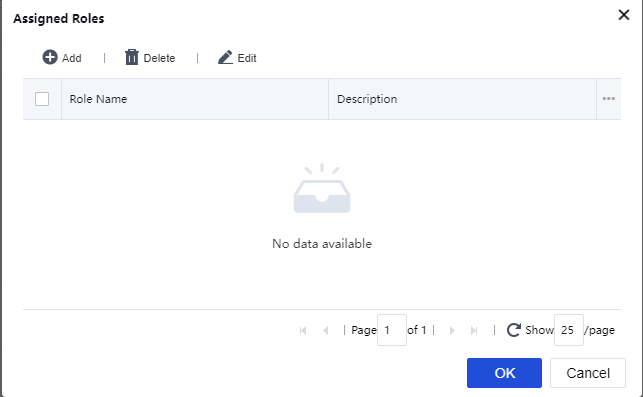
Click Add to enter the Select Role page, as shown below:
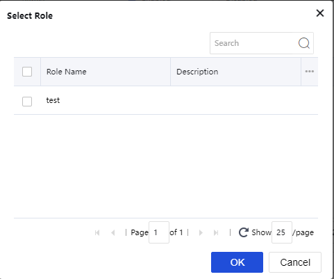
Select the checkbox next to the desired roles and click the OK button. The roles are added to the Assigned Roles page.
Click the OK button and name the assigned roles filled in the Roles field.
If the desired role is not found in the list, click Create + Associate to create a new role and associate with the user group. (The procedures of creating a role are the same as that in the Roles Adding section).
To remove a role from the list, select the role and click Delete.
To edit a role, select the role and click Edit.
Searching for Users
At the upper right of the Local Users page, there is a Search tool intended for searching for users or groups, as shown below:
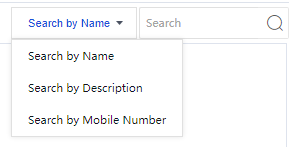
To search for a user or group by name, description, or mobile number, select the corresponding option. Enter the keyword in the search box, then click the magnifier icon, or press Enter key.
To sort users by name or description, in ascending or descending order, click Name or Description in the column header.
To filter users and view only one category of users, click Type in the column header, as shown below:
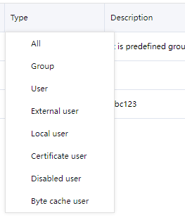
Managing Hardware IDs
On the Local Users page, click Hardware ID to enter the Hardware ID page, as shown below:
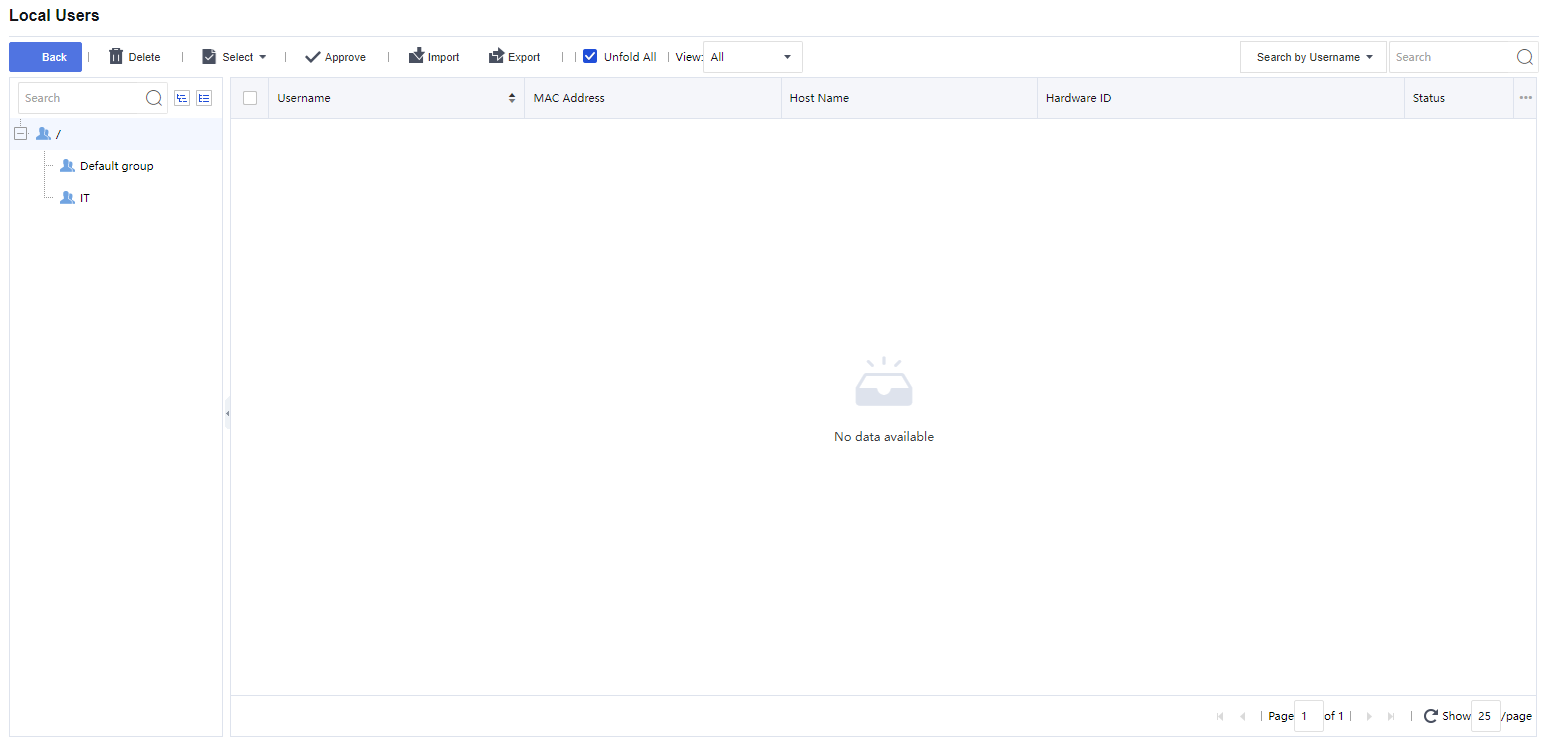
The following are some optional operations on the Hardware ID page:
Delete: Click it to remove the selected user and/or group.
Select: Click Select > On All Pages or On current page to select all the hardware IDs or only those showing on the current page. Click Select > Cancel to deselect users.
Approve: Click it to approve the selected hardware ID(s). The corresponding user will be able to pass hardware ID-based authentication.
View: Filter the hardware IDs. Choose a certain type of hardware IDs to show on the page. For example All, The approved or Not approved hardware IDs.
Search: Use the search tool on the upper right of the page to search for hardware ID based on username or hostname.
Import: Click it to import hardware IDs manually, as shown below:
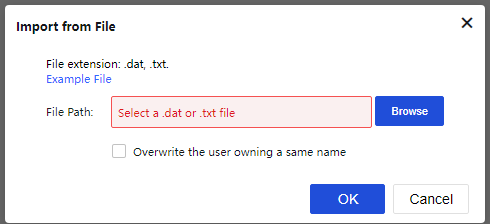
For the file format and maintaining the file containing hardware IDs, click the Example File link to download a copy to the local computer and maintain the hardware ID as instructed.
Overwrite the user owning a same name: If any imported user owns the name of an existing user, selecting this option will import that user and overwrite the existing user, including hardware ID and other information.
Click the Browse button to select a file and Open to upload it. Then, click OK to proceed.
Export: Click it to export the desired hardware IDs and save them into the computer, as shown in the figure below:
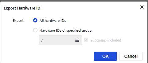
Specify the hardware IDs that you want to export.
To export all the hardware IDs, select All hardware IDs and click OK. All the hardware IDs will be written into a file that will then be saved on the computer.
To export the desired hardware IDs of a specific user group, select Hardware IDs of specified group and click the text box to specify a user group, as shown below:
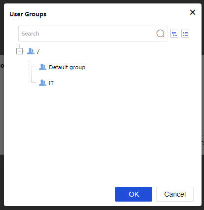
Click the OK button and the name of the selected user group is filled in the text box, as shown in the figure below:
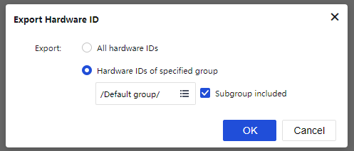
To export the hardware IDs of the users that are included in the subgroups of the specified user group, select the checkbox next to the Subgroup included. If this option is not selected, only the hardware IDs of the direct users in the selected group will be exported.
Click OK to write the hardware IDs into a file and download the file to the computer.
Importing User to Device
On the Local Users page, click Import and select Import Users from File to import users into Network Secure from a file as shown in the figure below:
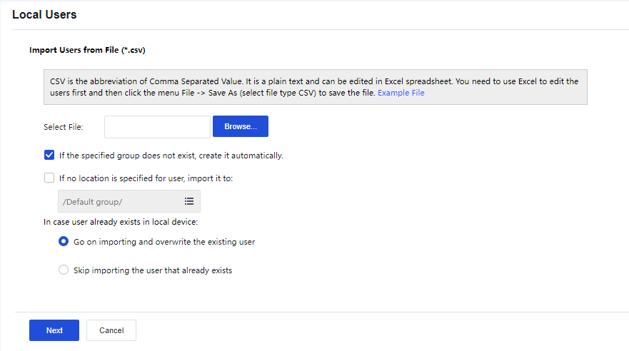
Select File: Click Browse to select a CSV file that contains user information, such as username, path, description, password, mobile number, etc., among which the username is required, and others are optional. For more details on maintaining and editing the CSV file, click the Example File link to download a copy and refer to the instructions.
If the specified group does not exist, create it automatically: This happens if the Added to Group of some users in the CSV file does not match any of the user groups on this Sangfor device.
If no location is specified for user, import it to: This specifies the user group to which these users will be added if the Added to Group column is not filled in for some users in the CSV file.
In case user already exists in local device: This means the imported user’s name conflicts with an existing user’s name. Select Go on importing and overwrite the existing user to overwrite the existing one, or select Skip importing the user that already exists not to overwrite the existing one.
Next: Click to import the users and add them into the specified user group.
Moving Users to Another Group
- On the Local Users page, select the desired user/group(s) and click Move (on the toolbar) to enter the User Groups page, as shown below:
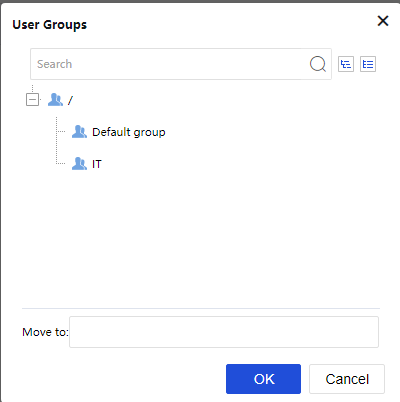
-
Select a user group to which the user/group(s) is added.
-
Click the OK button.
More Options
The More options include Export, Associate with Role, and Advanced Search. See the figure below:
Export
- Click More > Export to enter the Export Users page, as shown in the figure below:
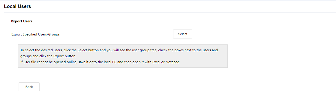
- Select the objects that you want to export as shown below:
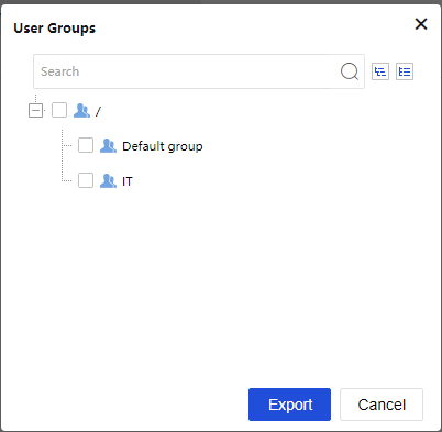
- Select the desired user group and then click the Export button. The selected user will be written into a CSV file and saved on the local computer. The exported user information includes username, group path, password (encrypted by an algorithm developed by SANGFOR), mobile number, description, and user’s last login time, as shown below:
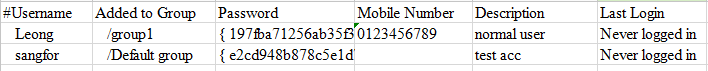
Associating with Roles
- Click More > Associate with Role to enter the Roles Associated With xxx page, as shown below:
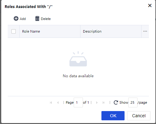
- Click Add to enter the Roles page, as shown in the figure below:
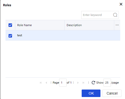
The roles on the Roles page are predefined under Network > SSL VPN > Roles.
-
Select the checkbox next to the role that you want to associate with the selected user or group.
-
Click the OK button and then the Submit button to save the settings.
Advanced Search
Click More > Advanced Search to open the Advanced Search page. The criteria for advanced search are as shown in the figure below:
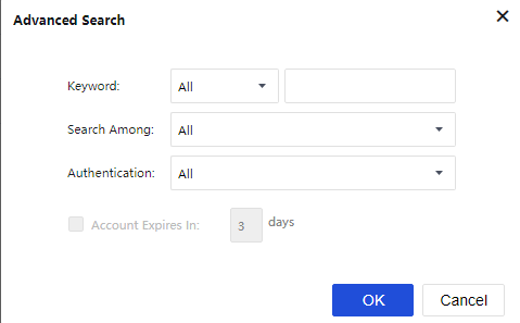
Search criteria are keyword, type of keyword, type of user, authentication method, and the user account expiration interval.
Viewing Associated Resources of Use
To see what resources are available to a certain user or group, select that user or group and click Associated Resources. The resources available to the selected user or group are as shown below:
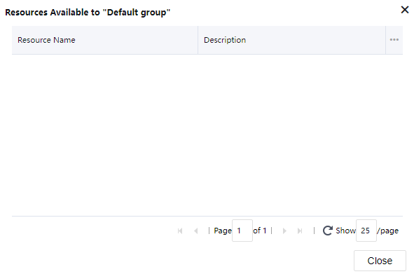
Resources
The resources mentioned in this section are the resources that specified users can access over SSL VPN. The only resource type available for SSL VPN in Network Secure is the TCP application. Navigate to Network > SSL VPN > Resources. The Resources page is as shown in the figure below:
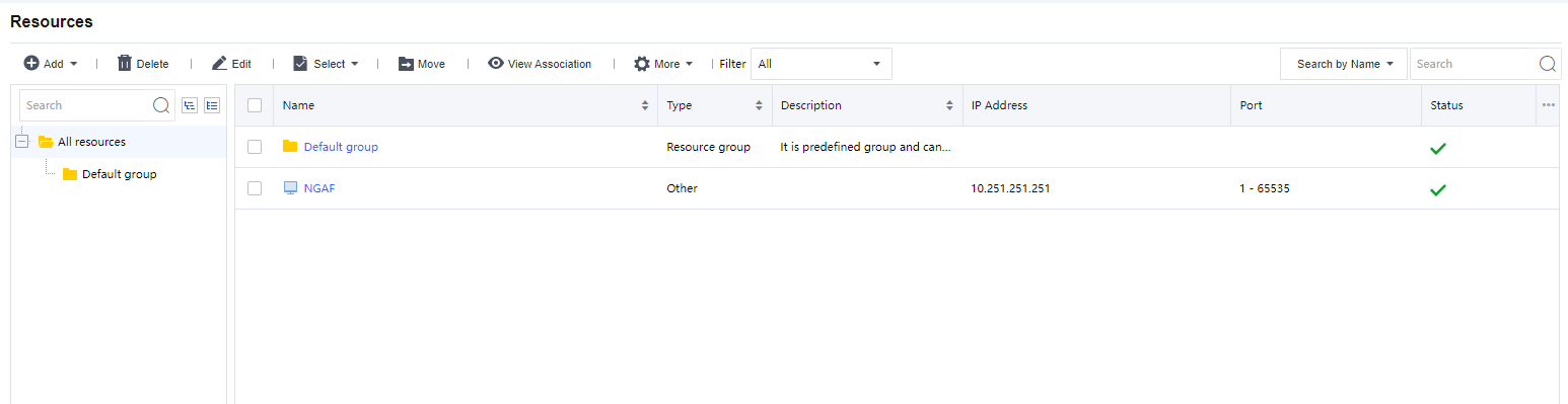
A resource group could contain several resource entries. Similar to user management, resources could be grouped according to categories and associated users or groups, etc. Most administrators welcome this kind of management because it makes resources more distinguishable. Navigate to Network > SSL VPN > Resources > All resources and click the resource group. The resources included in the group are displayed on the right pane. Default group is a group protected by the system and cannot be deleted, but its attributes can be modified.
Resource Group
- Click Add > Resource Group to enter the Edit Resource Group page, as shown in the figure below:
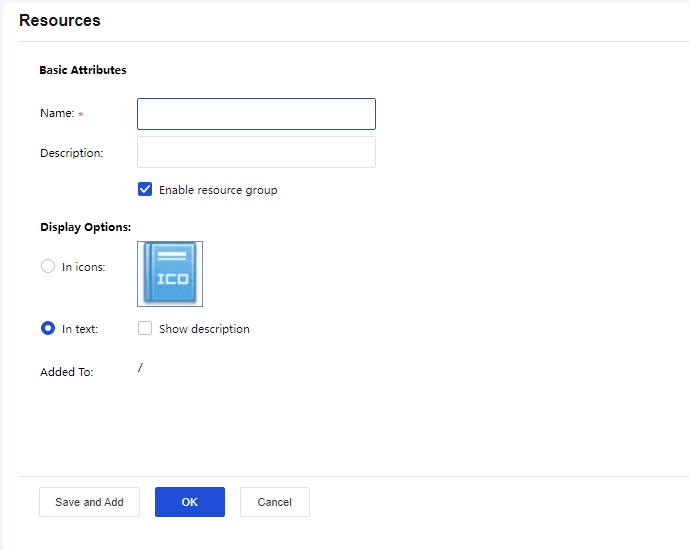
- Configure the Basic Attributes of the resource group. The following are the basic attributes:
Name/Description: Indicate the name and description of the resource group. This name will be seen on the Resources page after the user successfully logs in to the SSL VPN.
Display Options: Indicate the way resources are displayed on the Resources page, in icons, or text. If In icons is selected, define the icon size, 48*48, 64*64, or 128*128, so that the resources will be displayed in the icon as wanted. If In text is selected, you may select Show description of the resource.
Added To: Indicate the resource group to which this group is added. By default, the resource group is added to the root group (/).
TCP Application
TCP application is a resource that allows end-users to use C/S-based or TCP-based applications on their local computer to access corporate resources and servers over SSL VPN.
- Click Add > TCP App to enter the Edit TCP Application page, as shown in the figure below:
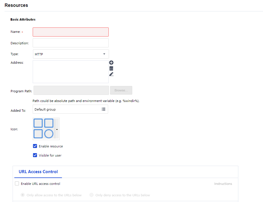
- Configure the Basic Attributes of the TCP application. The following are the basic attributes:
Name/Description: Indicate the name and description of the TCP resource. This name may be seen on the Resources page after the user logs in to the SSL VPN.
Type: Indicate the type of the TCP application. Some common types are built into the Sangfor device. This selection determines the port number entered in the Port field automatically. If the TCP application is not any of the built-in types, select Other and configure the port manually.
Address: Indicate the address of the TCP resource. Click the Add icon to enter the Add/Edit Resource Address page. To add one address entry (IP address, domain name, or IP range), select the Add Address tab. To add multiple entries of addresses, select the Add Multiple Addresses tab, as shown in the figures below:
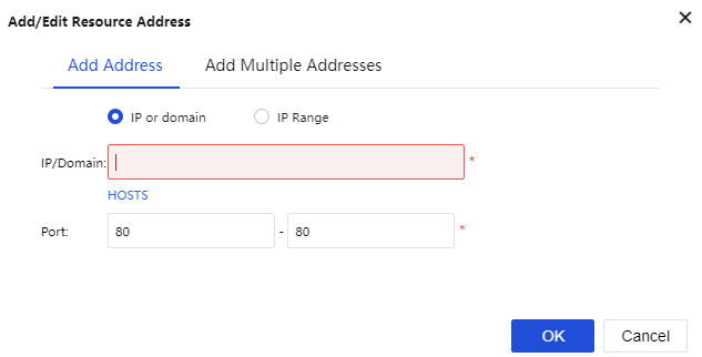
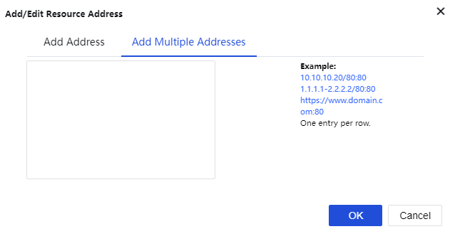
Port indicates the port used by this TCP application to provide services. For built-in types of TCP applications, this port is predefined. For Other types of TCP applications, enter the corresponding port number.
Program Path: Indicate the path of the client software program that may be used by the C/S (client/server) application.
Added To: Indicate the resource group to which this resource is added. By default, the selected resource group is the Default group (to configure the resource group, refer to the Adding/Editing Resource Group section).
Enable resource: To set the availability of this resource.
Visible for user: Selecting this option will make the resource visible to connecting users on the Resources page. Invisibility here only means that the resource is not seen on the Resources page. It is still accessible to the user.
URL Access Control: URL Access Control for HTTP resources:
Enable the URL Access Control function.
Choose the action for the access control, either allow or deny.
Add URL.
Click Instructions to display the URL access control instructions as the figure below:
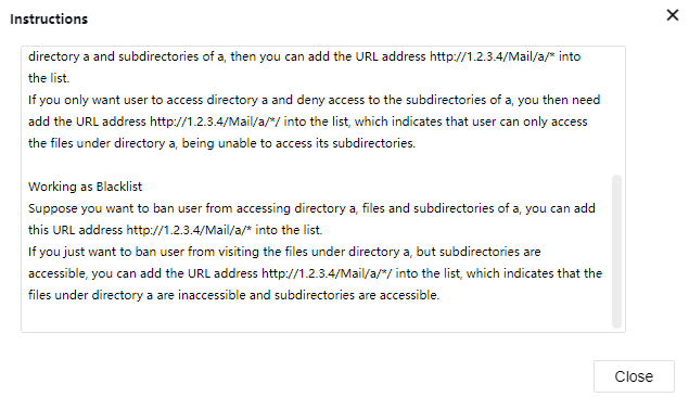
Note:
- The driver and plug-in for the TCP application will be installed automatically to the PC when the user logs in to SSL VPN for the first time. After that, the user must log in to Windows with an administrator account. If Windows firewall or Anti-Virus software is running, these applications must be disabled or turned off first to avoid plugin installation problems.
- TCP application does not support file sharing type.
L3VPN
L3VPN is used to define, configure, and manage Intranet SSL VPN resources using multiple IP protocols and can access using TCP/UDP/ICMP protocols at the same time.
- Click Add > L3VPN App to enter the Edit L3VPN page, as shown in the figure below.
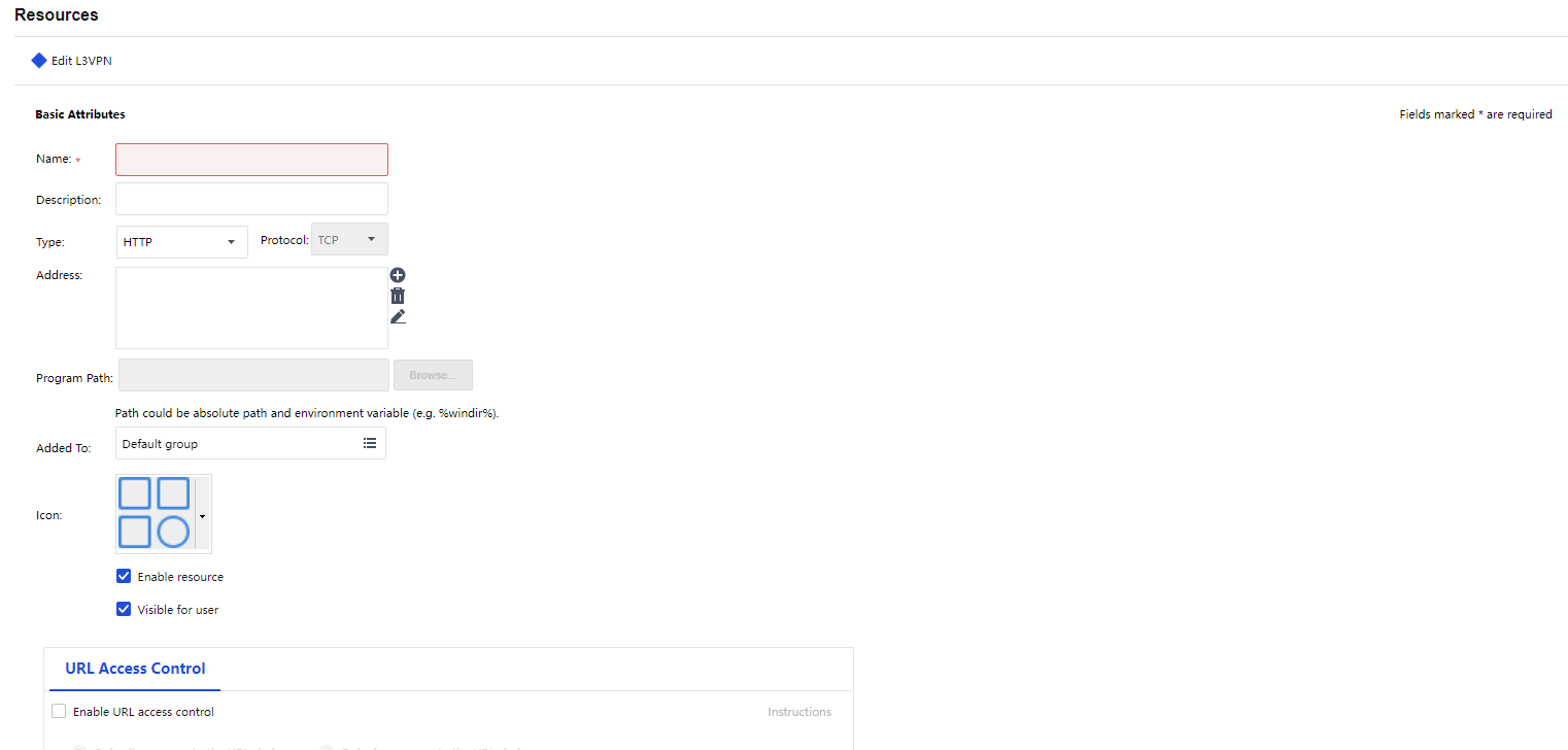
- Configure the Basic Attributes of the LVPN resource. The following are the basic attributes:
Name/Description: Indicate the name and description of the L3VPN resource. This name may be seen on the Resources page after the user logs in to the SSL VPN.
Type: Indicate the type of the L3VPN. Some common types are built into the Sangfor device. This selection determines the port number entered in the Port field automatically. If the L3VPNis not any of the built-in types, select Other and configure the port manually.
Address: Indicate the address of the LVPN resource. Click the Add icon to enter the Add/Edit Resource Address page. To add one address entry (IP address, domain name, or IP range), select the Add Address tab. To add multiple entries of addresses, select the Add Multiple Addresses tab, as shown in the figures below:
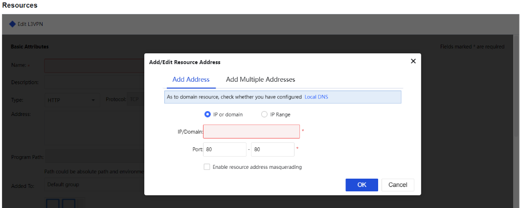
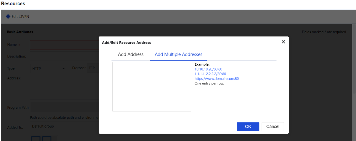
Port indicates the port used by this L3VPN to provide services. For built-in types of L3VPN, this port is predefined. For Other types of L3VPN, enter the corresponding port number.
Program Path: Indicate the path of the client software program that may be used by the C/S (client/server) application.
Added To: Indicate the resource group to which this resource is added. By default, the selected resource group is the Default group (to configure the resource group, refer to the Adding/Editing Resource Group section).
Enable resource: To set the availability of this resource.
Visible for user: Selecting this option will make the resource visible to connecting users on the Resources page. Invisibility here only means that the resource is not seen on the Resources page. It is still accessible to the user.
URL Access Control: URL Access Control for HTTP resources:
Enable the URL Access Control function.
Choose the action for the access control, either allow or deny.
Add URL.
Click Instructions to display the URL access control instructions as the figure below:
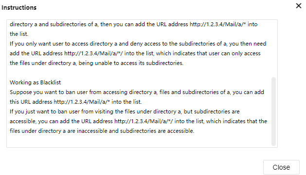
More
Other functions include Export Resources, Import Resources , Sort Resources, and Sort Resource Groups.
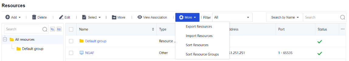
Export Resources
The export resource function will export resources from resource usage into a file, as shown in the figure below:
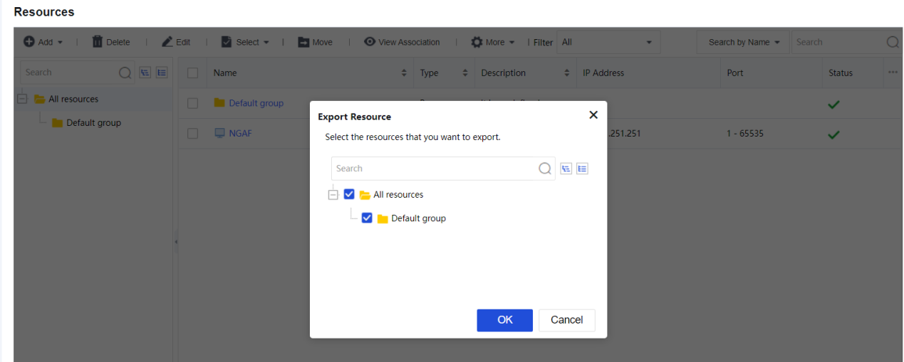
Click OK to save the selected resources into the rclist.csv file.
Import Resources
Import resources from an edited CSV file into resource usage.
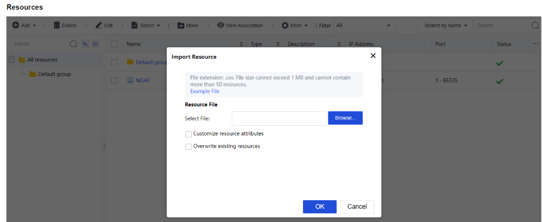
Click Example File to download the .csv file template for resource import.
Select Customize resource attributes to import resources to the existing resource group and be able to add a description for the resources.
Select Overwrite existing resources to replace the existing resources if the imported resources have the same name.
Sort Resources
Selecting a resource group and clicking the Sort Resources allows you to sort resources inside the resource group, as shown in the figure below:
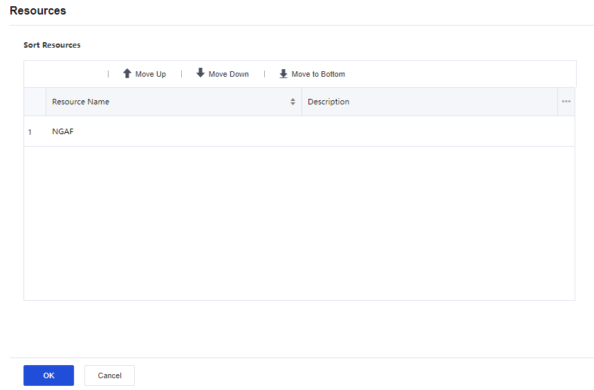
Sort Resource Groups
Resource sorting can rearrange the sequence for all resources by Move to Top, Move Up, Move Down , and Move to Bottom, as shown in the figure below:

Other than the abovementioned operations, functions such as Delete, Edit, Select, and Move can be applied to the resources.

The Select option is used to select the resource or resource group on the current page or all pages. Choose the desired resources and click Move to move the resources to another resource group.
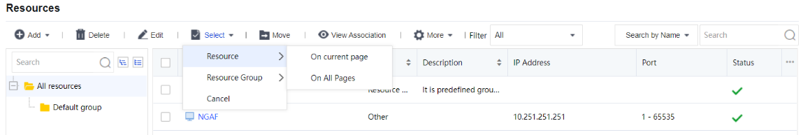
The Filter tool can be used to select resources based on the resource group or type. Available options are All, Resource Group, TCP App, and L3VPN App.
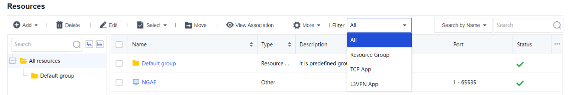
Roles
A role is an intermediate that builds a connection between the user/group and resources. More specifically, designates internal resources to the user or group. Users can only access the designated internal resources over SSL VPN. This kind of association enables one or multiple users or groups to associate with one or multiple resources, facilitating control over users’ access to corporate resources. Navigate to Network > SSL VPN > Roles. The Roles page will appear as shown below:
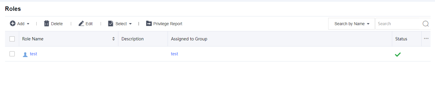
The Roles page includes the following contents:
Search by Name/Description/User (Group): To search for a specific role or type of role, select an option, enter the keyword into the search box, and click the magnifier icon.
Name/Description indicates the name/description of the role. User/Group indicates the user and/or group that the role is assigned.
Role Name: Indicate the name of the role.
Description: Indicate description of the role.
Add: Click it to add a new role directly or use an existing role as a template.
Edit: Click it to edit a selected role.
Delete: Click it to remove the selected role(s).
Adding Role
- Click Add > Add Role to enter the Add Role page, as shown in the figure below:
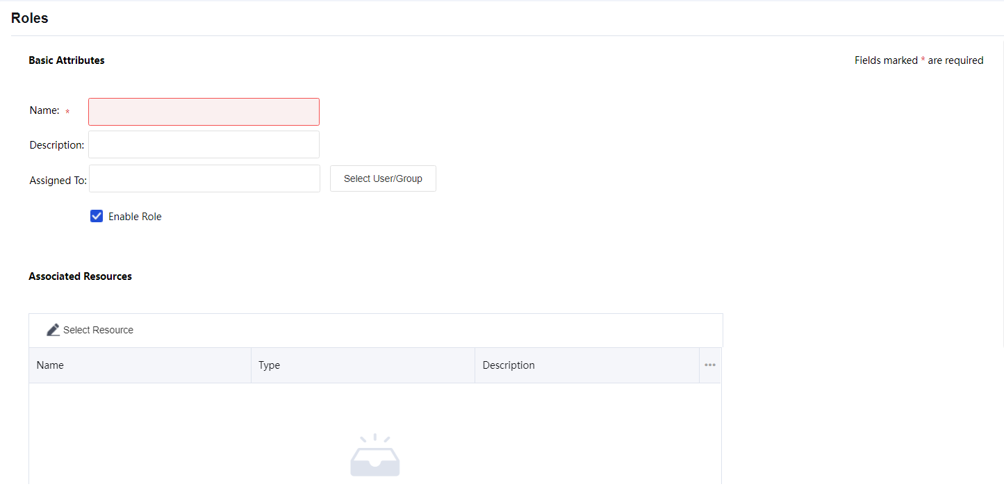
- Configure the Basic Attributes of the role. The following are the basic attributes:
Name: Specify the name of the role.
Description: Specify the description of the role.
Assigned To: Configure the user and/or group that can access the associated resources.
To specify user and group, click the Select User/Group button, and all the predefined users and groups on the User Management page are seen in the list, as shown below:
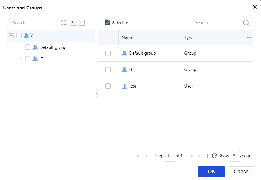
Select the user or group to which the role is to be assigned and click OK.
- Configure Associated Resources. Click Select Resource to enter the Resources page and select the resources that the associated users of this role can access, as shown below:
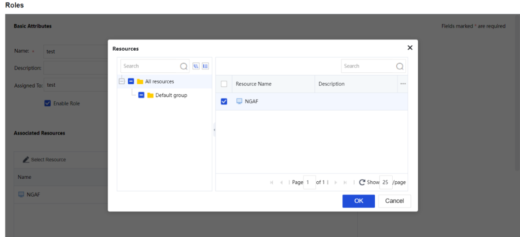
- Click the Save and Add button on the Add Role page to save the settings.
Generate Privilege Report
Privilege Report is generated to view resources accessible to certain users, as shown in the following figure:
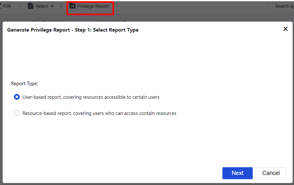
Click Next to select a user and click Finish to download the generated CSV file.
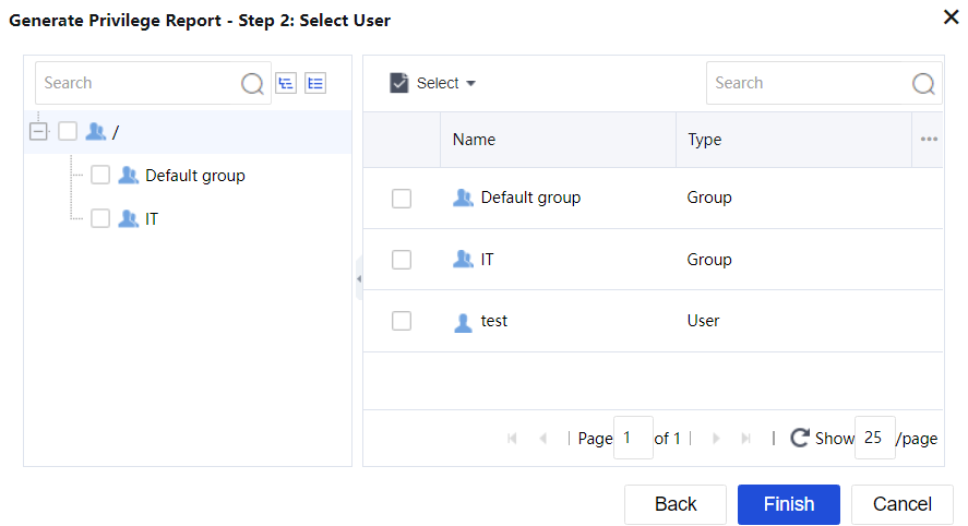
Login Options
Navigate to Network > SSL VPN > Login Options to configure the login port and web agent settings, as shown in the figure below:
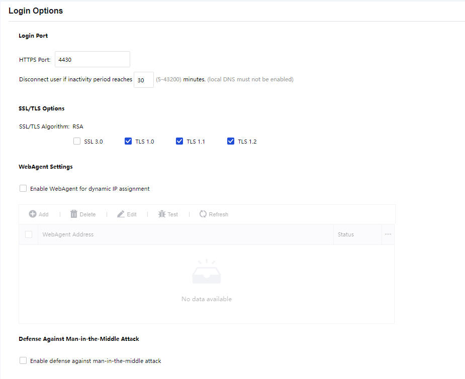
HTTPS Port: Specify the HTTPS port on which the SSL VPN service is being listened.
SSL/TLS Options: Support to enable SSL or TLS settings.
WebAgent Settings:
Select Enable WebAgent for dynamic IP assignment to enable this feature. The Sangfor device will get an IP using Web Agent dynamic addressing if it does not use a static Internet IP address. To add a Web agent entry:
- Click Add to enter the Add WebAgent page, as shown below:
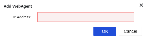
-
Enter the Web Agent address into the IP Address field and click OK.
-
To check the connectivity of a Web Agent, select a Web Agent and click Test. If the address is correct, the Sangfor device will successfully connect to this Web Agent. Otherwise, the connection will fail, as shown in the figure below:
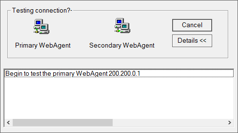
Before the test begins, certain ActiveX control may need to be installed (as shown below).
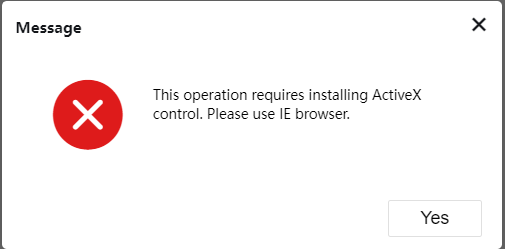
-
To remove or edit a Web Agent entry, select the desired entry and click Delete or Edit.
-
To modify the password of a Web Agent, select the desired entry and click Modify PWD. Modifying passwords can prevent an unauthorized user from using and updating a false IP address on the Web Agent page.
-
To refresh the status of the Web Agent, click Refresh.
Security protection detection:
It is used to defend against man-in-the-middle attacks and host header attacks. See the figure below:
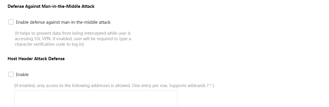
Virtual IP Pool
The virtual IP pool provides virtual IP addresses to the SSL VPN users who access via L3VPN resources, and the IP pool should not conflict with other intranet network segments. We recommend using isolated network segments or keeping the default IP pool. The page is shown as below:
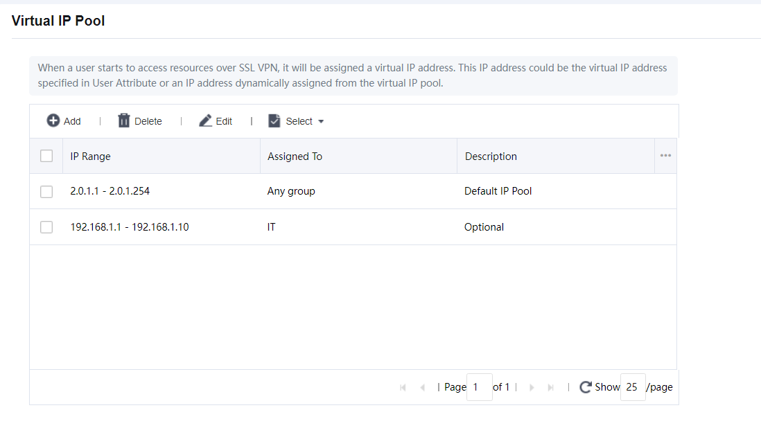
IP Range: IP pool configuration for start IP to the end IP address.
Assigned To: Target SSL VPN user or group to assign with a selected IP range.
Description: Configure the description of the IP pool range.
Click Add to create a new entry for the IP pool, as shown in the figure below:
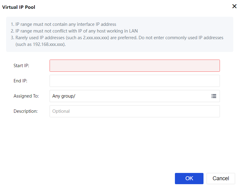
Note:
- IP segments in the virtual IP pool must not conflict with intranet IP segments.
- The IP addresses in the virtual IP pool must not include the IP addresses configured on the other interfaces.
Logging In
Navigate to Network > SSL VPN > Logging In. The Logging In page is as shown in the figure below.
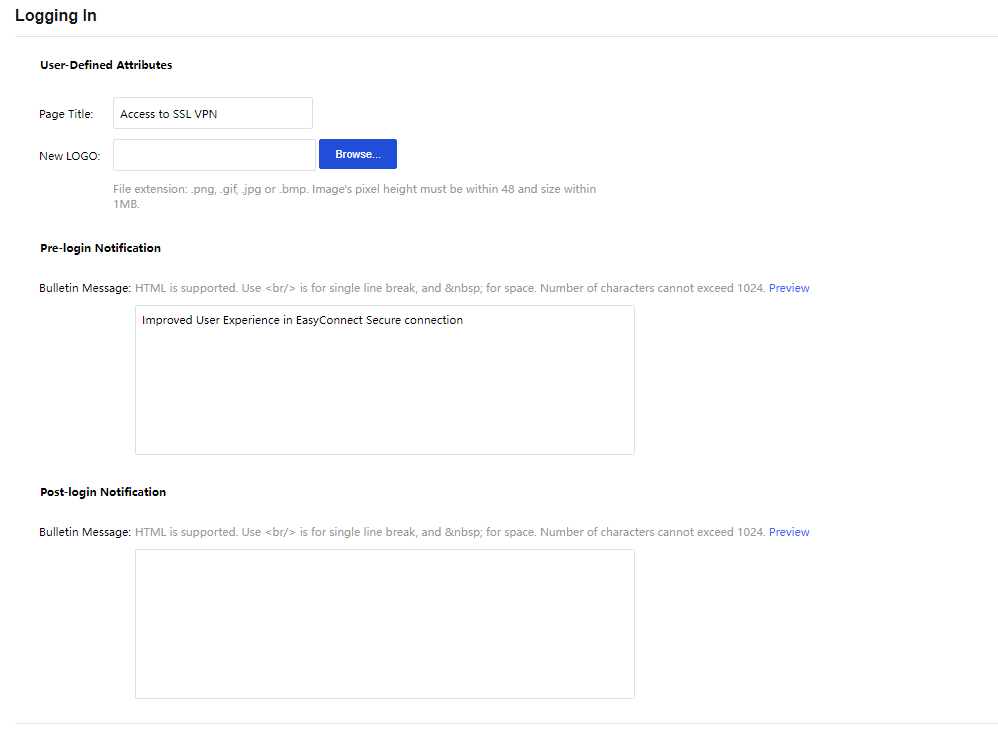
Page Title: Specify the caption of the login page.
New LOGO: Upload a new logo to be displayed when accessing the SSL VPN page.
Pre-login Notification:
Bulletin Message: Enter the message into the text box. This bulletin message will be seen on the portal before the users log in to the SSL VPN. Maximum 1024 characters are allowed, and HTML is supported. To preview the bulletin message, click Preview.
Post-login Notification:
Bulletin Message: Enter the message into the text box. This bulletin message will be seen on the portal after the users log in to the SSL VPN. Maximum 1024 characters are allowed, and HTML is supported. To preview the bulletin message, click Preview.
Authentication
Authentication covers settings related to primary and secondary authentication methods. Navigate to Network > SSL VPN > Authentication. The Authentication page will appear, as shown in the figure below:
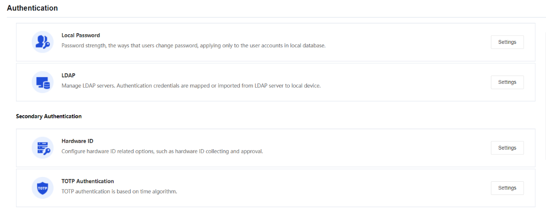
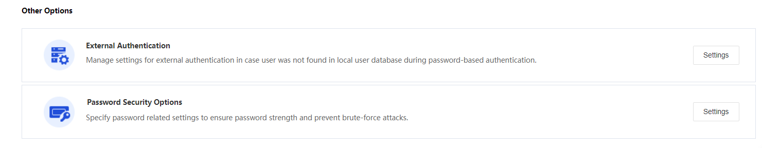
Primary Authentication Method
Local Password
The Local Password authentication method in Network Secure is a local password-based authentication. The settings related to the local password-based authentication include password security options and username options. Click the Settings button in the Local Password section to enter the Local Password Based Authentication page, as shown in the figure below:
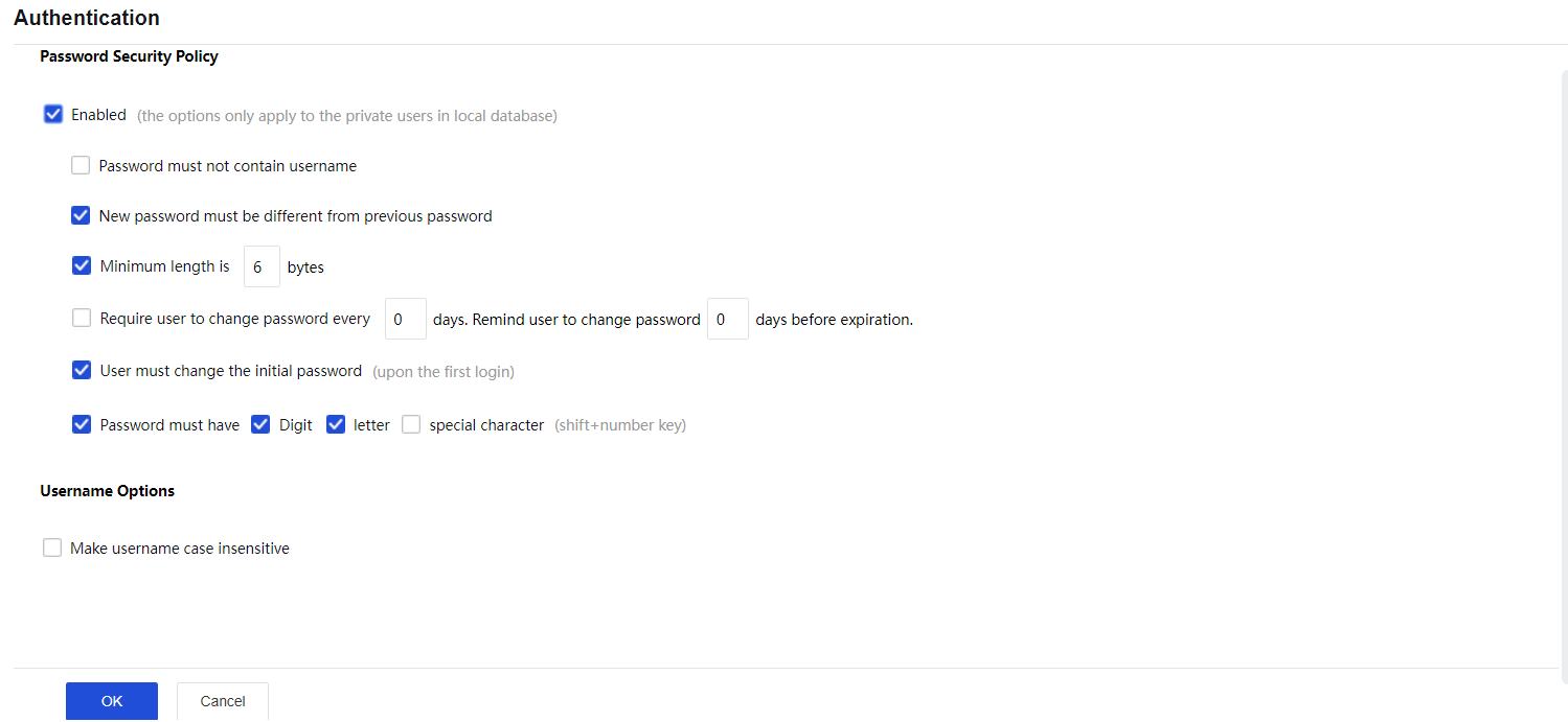
The Local Password-Based Authentication page includes the following contents:
Password Security Policy: Configure the password strength and how users change passwords.
Username Options: If the Make username case insensitive is selected, the case of username will be insensitive when users enter the credentials to log in to SSL VPN.
LDAP
Click the Settings button in the LDAP section. Then, click Add to add an LDAP server, as shown in the figure below:
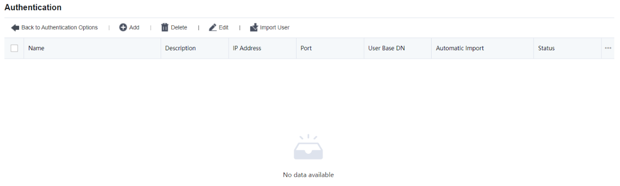
In the Basic Attributes section, set a server name, description, server IP address, authentication port, admin DN, admin password of a domain user, Base DN (path of the server where the user resides), timeout interval, and status.
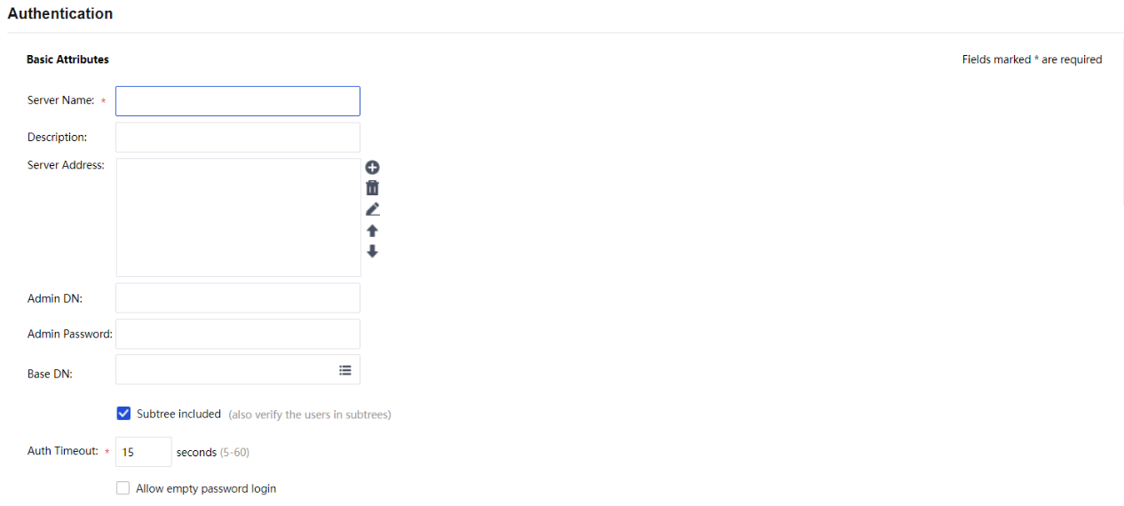

In the Advanced Options section, select the type of the server and specify the user attribute, and user filter. The following three types are supported: MS ActiveDirectory, LDAP server, and MS ActiveDirectory VPN.
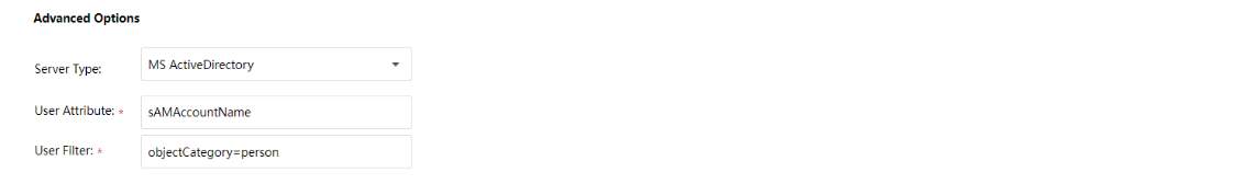
The Other Attributes section allows setting Group Mapping and Password Encryption. See the figure below:
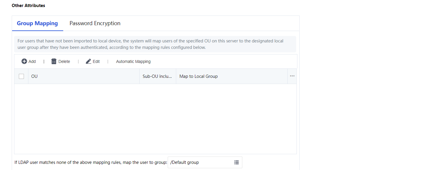
Secondary Authentication Method
The Secondary Authentication method in Network Secure is a Hardware ID-based authentication or TOTP authentication.
Hardware ID
According to a certain algorithm, the hardware ID is a unique serial number generated using the extracted features of hardware components in a computer. The uniqueness of computer components makes the generated hardware ID unique. Click the Settings button in the Hardware ID section to enter the Hardware ID Based Authentication page, as shown in the figure below:
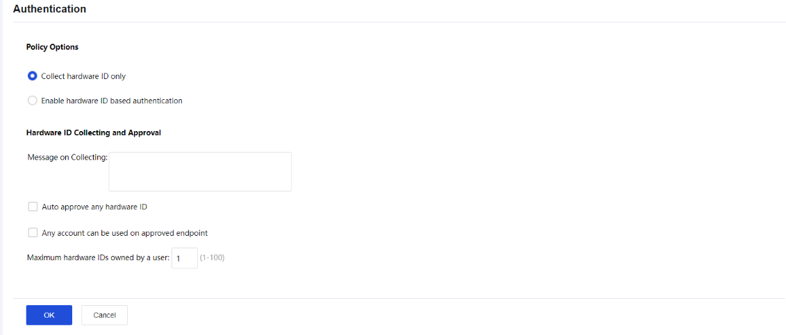
The Hardware ID Based Authentication page includes the following contents:
Collect hardware ID only: If this option is selected, the hardware IDs of endpoint computers will be collected, but the hardware ID-based authentication will not be enabled.
Enable hardware ID based authentication: If this option is selected, the hardware IDs of endpoint computers will be collected, and the hardware ID-based authentication will be enabled.
Message on Collecting: End-users will see the prompt message when they go through the hardware ID-based authentication.
Auto approve any hardware ID: This indicates that any hardware IDs submitted by the end-users will be approved, and the administrator does not need to approve them manually.
Any account can be used on approved endpoint: Indicate that hardware IDs submitted by any user from a certain endpoint(s) will be approved automatically if the administrator has ever approved the hardware ID of the endpoint(s).
Click OK to save the settings when the configuration is completed.
TOTP Authentication
TOTP, an abbreviation for Time-based One-Time Password, indicates a one-time password based on a timestamp algorithm. Based on the comparison between the client’s dynamic password and the clock of the dynamic token authentication server, a new password is usually generated every 30 or 60 seconds.
The client and server are required to maintain the correct clock very precisely to keep the one-time password generated to be consistent on both sides. Network Secure SSL VPN can combine with dynamic tokens based on TOTP protocol to achieve two-factor authentication for account security. The commonly used TOTP dynamic token clients are Google Authenticator, Microsoft Authenticator, M token, etc. This configuration guide uses Google Authenticator as an example.
TOTP Configuration Steps:
- Go to Network > SSLVPN > Authentication > TOTP Authentication and click the Settings button. Select Enable to enable the TOTP Authentication.
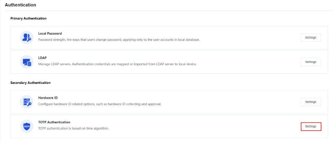
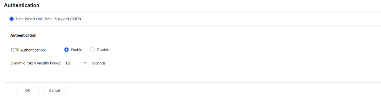
- To enable TOTP authentication on specific users, navigate to Network > SSL VPN > Local Users, select the user and click Edit. Next, select Dynamic Token Authentication > TOTP authentication.
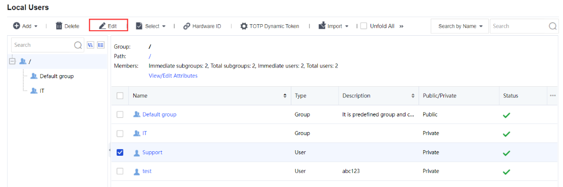
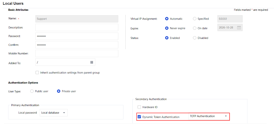
- On the Network > SSL VPN > Local Users > TOTP Dynamic Token page, check the TOTP authentication database to view which user is bound with TOTP authentication. You can see the User Type and Binding Time. Administrators can delete the user from the TOTP authentication database manually if the user loses their TOTP software.
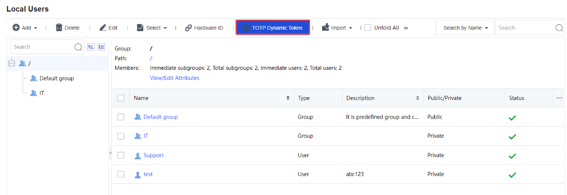
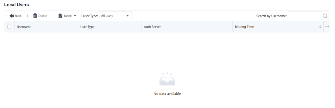
Verification on the Binding Relationship:
Administrators can check on the user authentication method in the online user list on the Network > SSL VPN > Online Users page, and the binding status on the Network > SSL VPN > Local Users > TOTP Dynamic Token page.
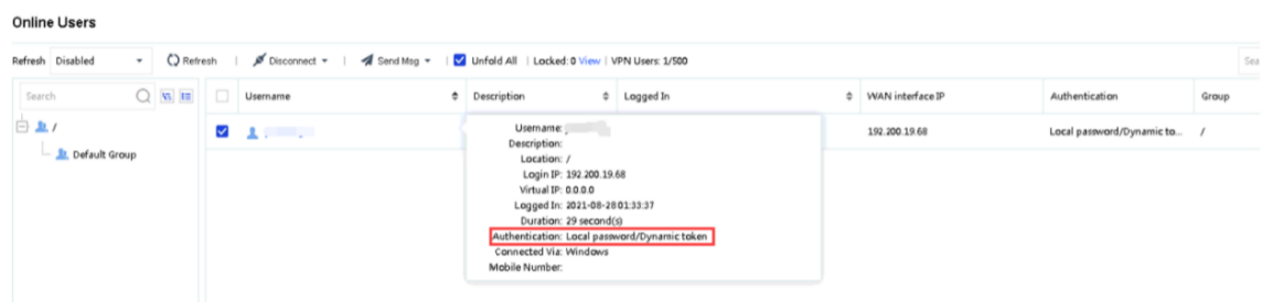
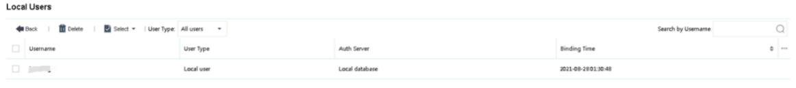
Other Options
External Authentication
It is used to sort the external authentication servers. See the figure below:
Password Security Options
Password security options are settings related to login when the user submits username and password to access the SSL VPN, including two parts, Login Security Options and Brute-force Login Prevention. Click the Settings button in the Password Security Options section to enter the Password Security Options page, as shown in the figure below:
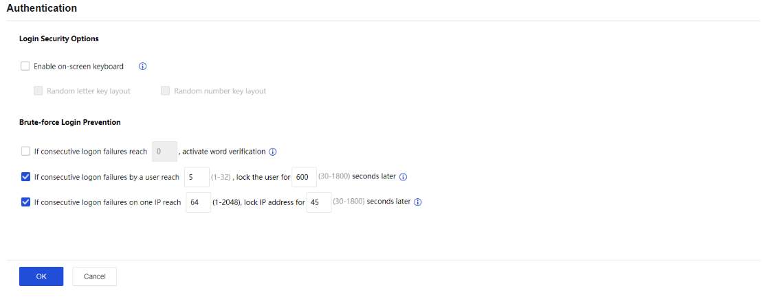
The Password Security Options page includes the following contents:
Enable on-screen keyboard: On-screen keyboard is a virtual keyboard available on the SSL VPN login page and can prevent input disclosure, enhancing security to the SSL VPN access. By enabling the other two options, Random letter key layout and Random number key layout, the letter keys and number keys on the virtual keyboard change positions randomly every time the user uses this keyboard. Thus, when the user logs in to the SSL VPN and wants to call the on-screen keyboard, they only need to click the keyboard icon next to the Password field on the login page, as shown in the figure below:
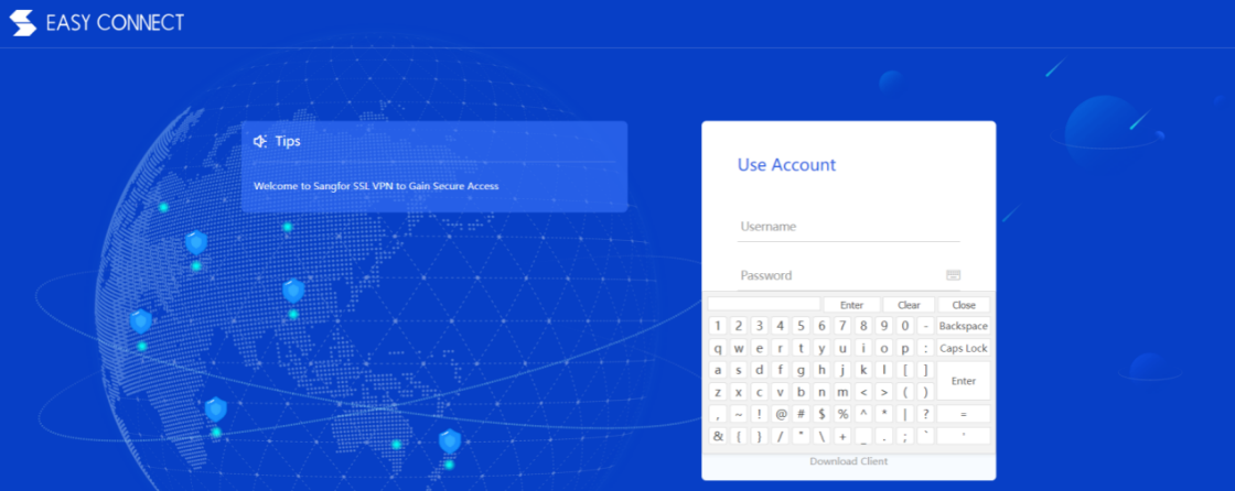
Brute-force Login Prevention: This security feature enables the system to take actions to stop brute-force login attempts. If the user fails to log in too many times, the login IP address or the user account can be locked up for some time, or word verification may be activated. The prompt given is as shown below:
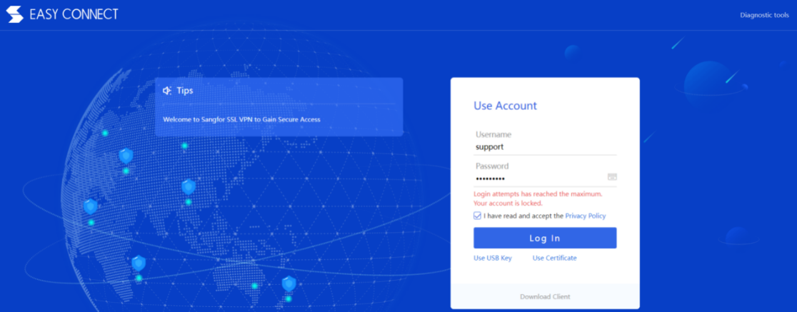
Certificate
The Certificate is intended for establishing sessions between the Sangfor device and the client. To view the current certificate or to generate a certificate for the Sangfor device, navigate to Network > SSL VPN > Certificate, as shown in the figure below:
The Certificate page includes the following contents:
View: Click it to view the detailed information of the current certificate.
Download: Click it to download the current device certificate.
Update: Click it to import a new certificate to take the place of the current one.
Create CSR: Click it to enter the Create a CSR for Device page to generate a certificate signing request (CSR) sent to the external CA to generate the device certificate. The page is as shown in the figure below:
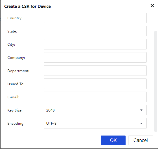
Configure the required fields and then click the OK button.
Once the certificate signing request is generated, click the Download link to download the request.
Resource Options
Resource options contain the parameters setting for L3VPN resources. The configuration page is as shown below:
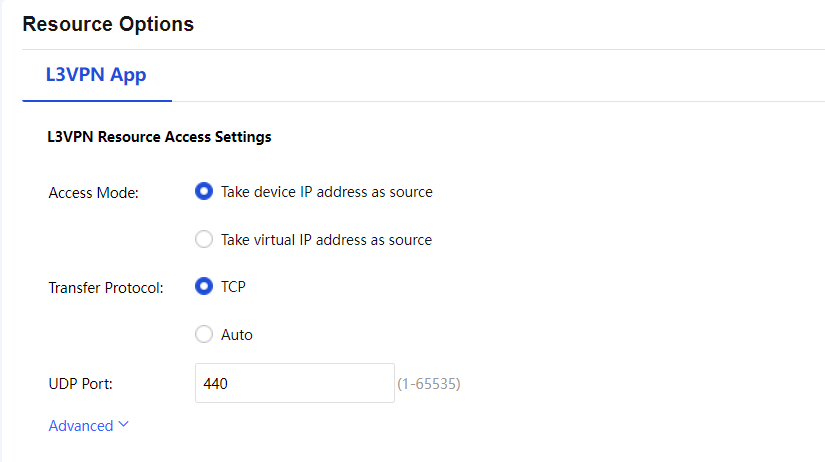
Access Mode: SSL VPN user L3VPN resource access mode can be defined either by using device IP address or virtual IP address as the source IP. If Take device IP address as source is chosen, the host/server in the internal network will receive the packets with the device IP address as the source IP address. If Take virtual IP address as source is chosen, the server will receive the packets with a virtual IP address as the source IP address. The virtual IP address is offered by the virtual IP pool mentioned in the previous section.
Transfer Protocol: To select L3VPN application transfer protocol (TCP or UDP). Click the Advanced Options to configure the IP of the Local Virtual Adapter.
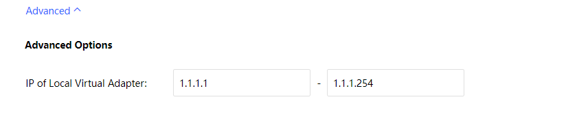
Local DNS
SSL VPN supports resources access only through an Internal DNS server. When there are such application resources, usually, the user will have several DNS servers for internal devices to resolve the domain when accessing the applications. The configuration will allow SSL VPN users to resolve the domain using the defined DNS server. The configuration page is as shown in the following figure.
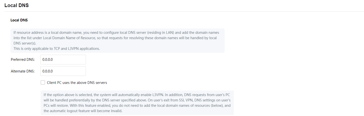

On the Local DNS page, there are Preferred DNS and Alternate DNS. You only need to configure the Preferred DNS if there is only one internal DNS. After the configuration, the Client PC uses the above DNS servers checkbox to activate the function.
With this feature enabled, it’s not allow to configure the local domain names of resources, and the automatic logout feature will become invalid.
The Local Domain Name of Resource are used if the address used in the resource is an internal domain name and the intranet has a dedicated DNS server for resolution. Add rules in Local Domain Name of Resource so that resolution requests for this part of the domain name are prioritized by the intranet DNS server.
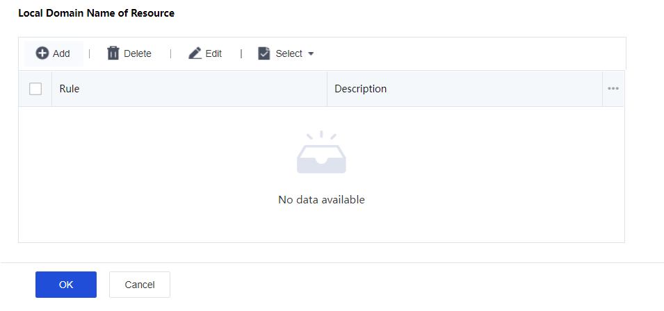
Click Add to enter the Add Domain Name of Resource page as shown below.
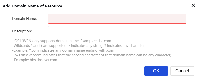
Domain Name: Define the domain name of resources to be accessed.
Description: Description of the domain name entry.
Note:
- If the resource application uses an internal domain name and there is an internal DNS server to resolve these domains, adding the Local Domain Name of Resource is recommended to prioritize the internal DNS server resolved. Otherwise, leave the section blank.
- The maximum supported resource is 100 entries, and only the English alphabet is supported.
Sangfor/IPSec VPN
The Sangfor/IPSec VPN feature allows you to establish IPSec VPN connections to Sangfor or third-party devices. It provides a secure communication channel for two private networks on the public network and ensures the security of connections using an encrypted channel.
VPN Status
The Status page shows the current VPN connection and network throughput, as shown in the following figure.

You can check the name and IP address of the peer device connected to the VPN, as well as the throughput on the VPN interface.
You can click Alert Trigger to set alert information for the VPN, as shown in the following figure.
In the Alert Trigger dialog box, you can set the Throughput (in/out), Packet loss (in/out), Jitter, and Latency parameters as required, to identify IPSec VPN exceptions quickly.
Note:
The Status page shows the current tunnel connection status of both IPSec VPN and Sangfor VPN, but the displayed tunnel connection information varies. For example, the tunnel packet loss (in/out), latency, jitter, and transmission type of the IPSec VPN are not displayed.
VPN Wizard
The VPN Wizard page provides guidance for you to select Sangfor VPN or IPSec VPN as the VPN protocol, as shown in the following figure.
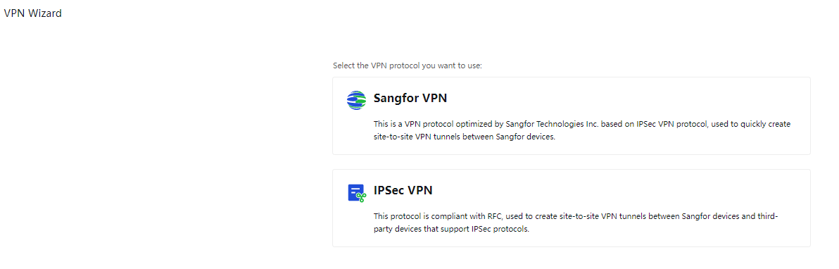
Sangfor VPN
Click Sangfor VPN and select a device deployment scenario. The options are Headquarters or Branch. For example, if you select Headquarters, the system automatically proceeds to the next step.
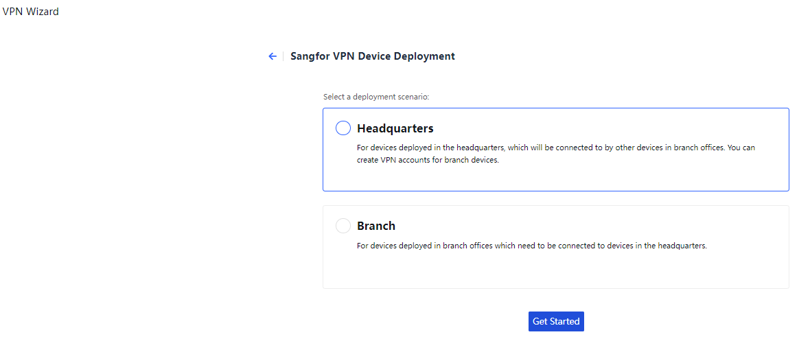
- Get Started
Configuration Check Results: Show the check results for the current deployment mode, available outbound interfaces, available intranet interfaces, VPN service port, and network connection status. If the status changes, you can click Check Again on the right to refresh the check results.
Collect Information: Show the information required for configuring the VPN for the device. For example, the HQ access address, local subnet, and certificate used for authentication.
Confirm the information and click Next.
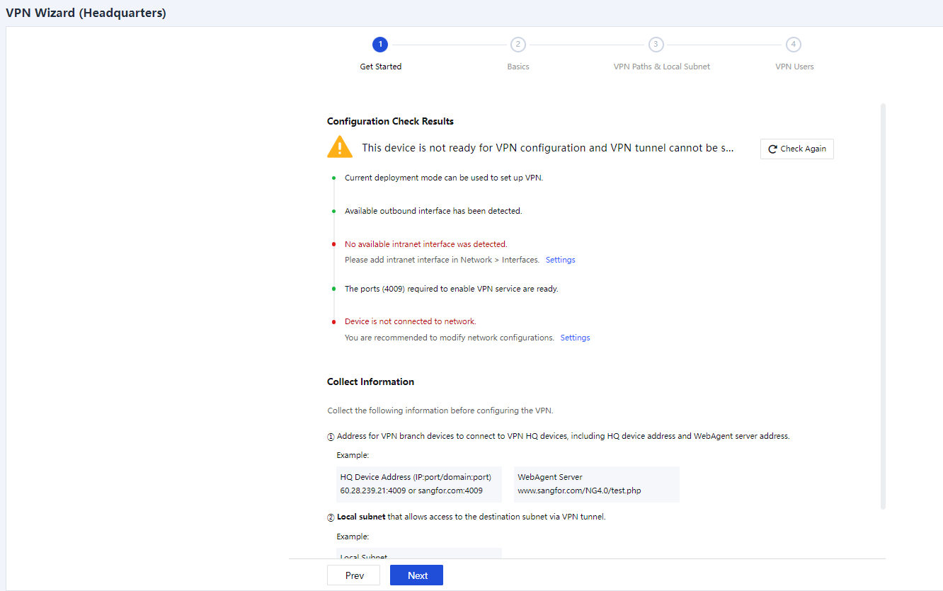
- Basics
VPN HQ Address: Enter the VPN access address provided by the current device as the VPN HQ device, in the format of IP address:Port number. Separate multiple IP addresses with the pound sign (#), for example, 202.102.2.35#60.25.5.36:4009.
Shared Key (Optional): The authentication password for a branch device to access the VPN HQ device. If this field is specified, you must enter the same password on the branch device to establish a VPN connection.
Confirm the information and click Next.
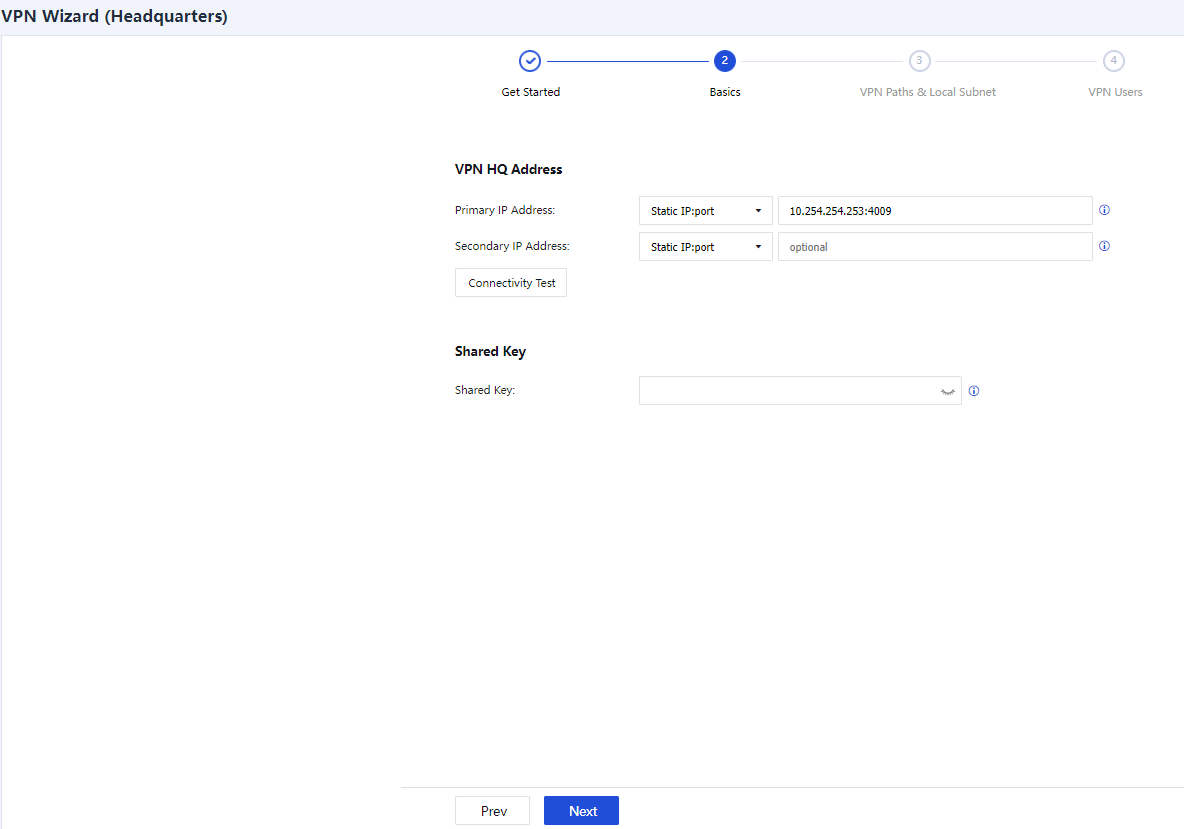
- VPN Paths & Local Subnet
VPN Paths: Add a WAN link for establishing the Sangfor VPN. You can also delete, enable, or disable a link by clicking Delete, Enable, or Disable.
Local Subnet Settings: Enter a local subnet to access the LAN of the peer device through the Sangfor VPN.
Confirm the information and click Next.
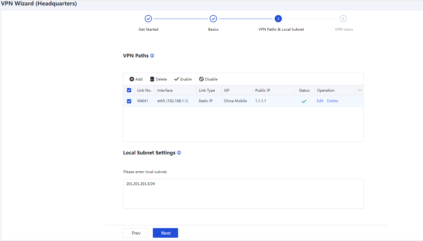
- VPN Users
You can create VPN users in either of the following ways:
Import Config File: Import the VPN usernames and passwords for branch devices from a CSV or TXT file.
Configure Now: Enter the VPN usernames and passwords for branch devices. For example, if you click Configure Now, the system automatically proceeds to the next step.
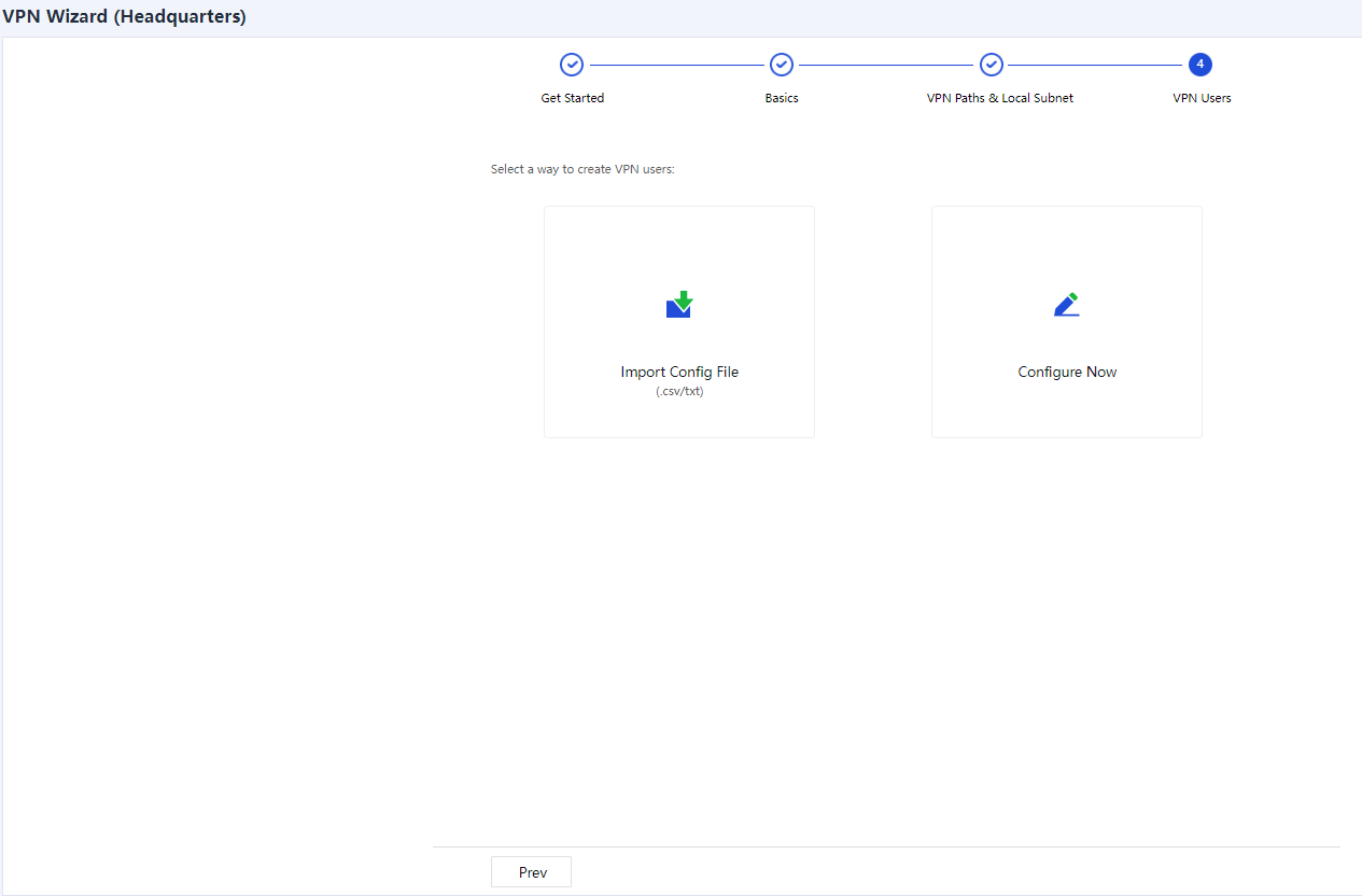
Set the VPN username and authentication method for each branch device. If you select Password based, enter a password for the branch device and click Add, as shown in the following figure.
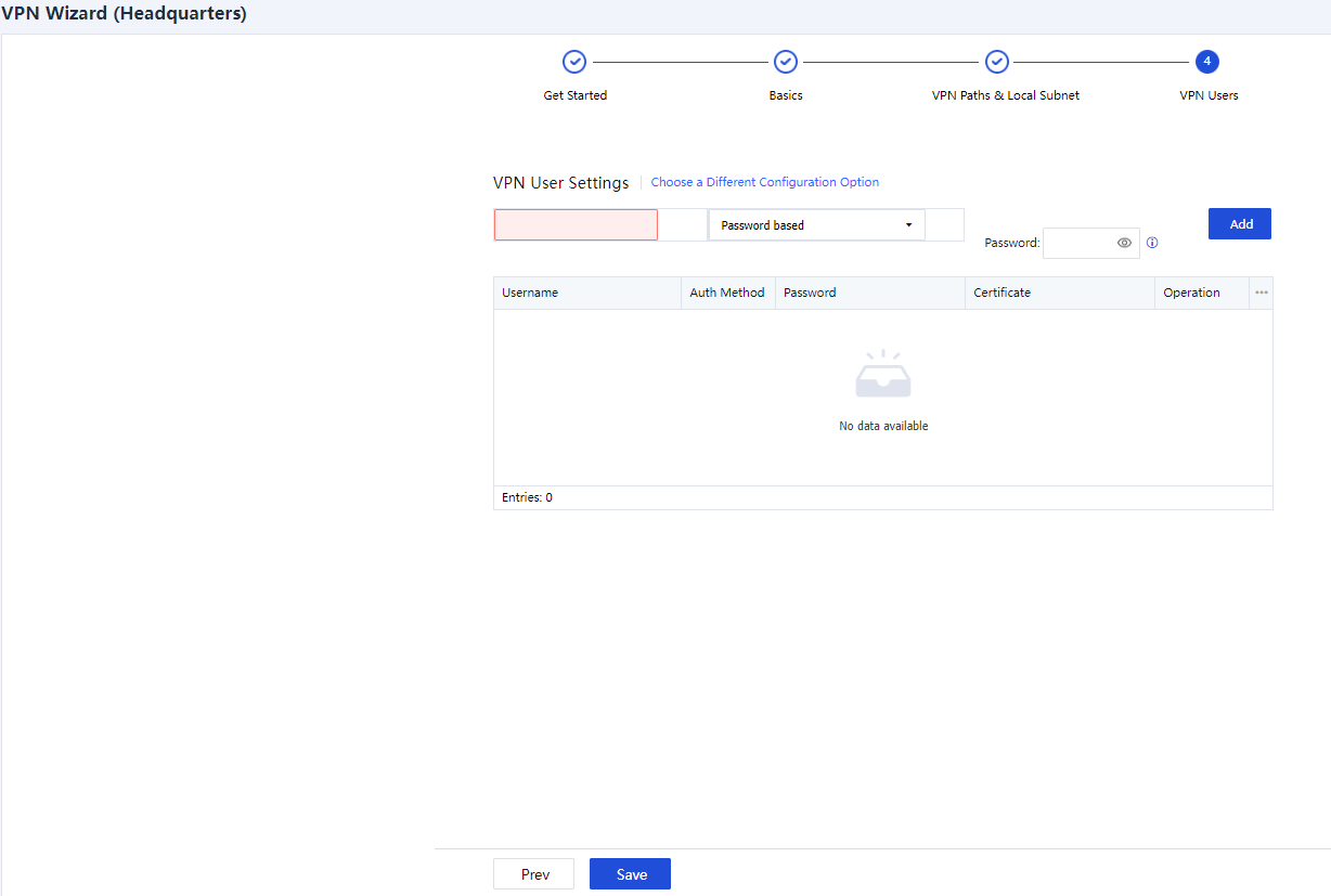
- Click Save. The Sangfor VPN configuration is completed.
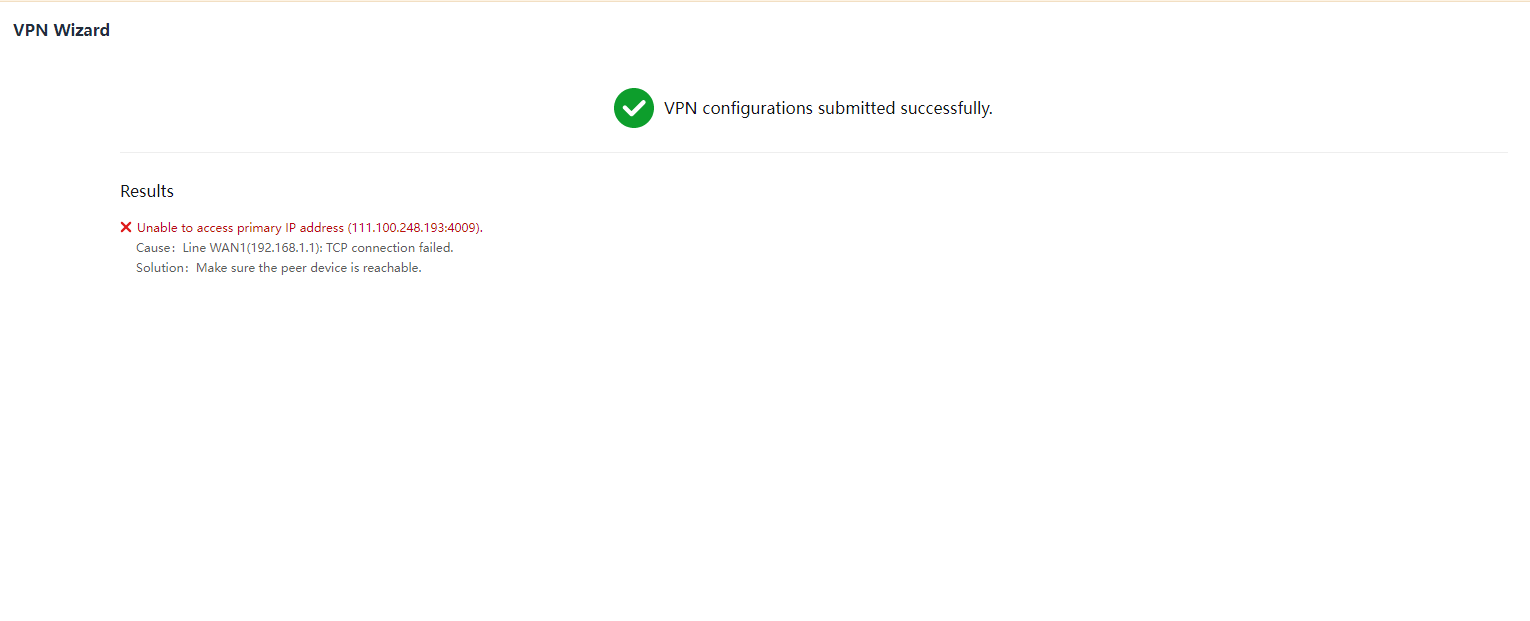
IPSec VPN
- Get started
On the VPN Wizard page, click IPSec VPN. The system automatically proceeds to the next page, as shown in the following figure.
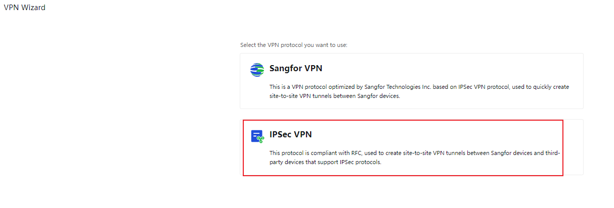
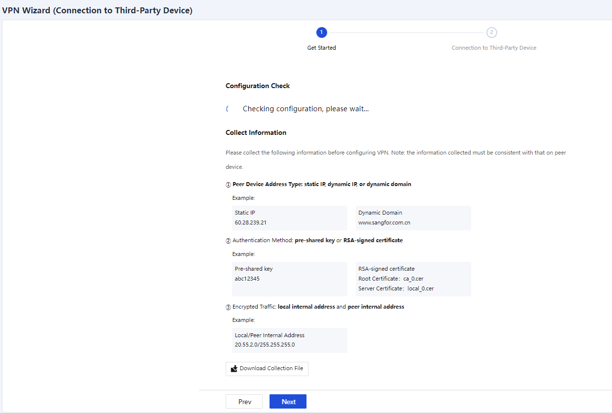
Configuration Check Results: Show the check results for the current deployment mode, available outbound interfaces, available intranet interfaces, VPN service port, number of licenses, and network connection status. If the status changes, you can click Check Again on the right to refresh the check results.
Collect Information: Show the information required for configuring the VPN for the device. For example, the peer device address and type, authentication method, and internal subnets of traffic to be encrypted.
Download Collection File: You can click this button to download the collection file template. The file content is shown in the following figure.
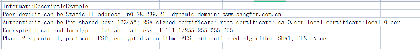
Confirm the information and click Next.
- Connection to Third-Party Device
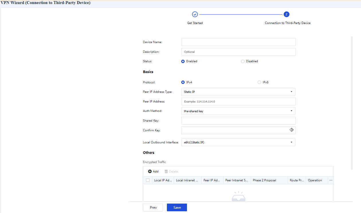
Device Name: Enter a name for the local IPSec device. This parameter is not verified in IPSec negotiation, and it applies only to the local network. You can set it as required.
Description (Optional): Enter a description of the device.
Status: Specify whether to enable or disable VPN for the current device.
Basics:
Peer IP Address Type: Select Static IP, Dynamic IP, or Dynamic Domain as required. If you select Static IP, enter the IP address of the peer device. If you select Dynamic Domain, enter the WAN domain name of the peer device.
Auth Method: Select Pre-shared key, Certificate based, or SM2 Certificate V1.1 as required.
Shared Key and Confirm Key: Enter the correct pre-shared key. Ensure both devices use the same pre-shared key.
Local Outbound Interface: Select an outbound interface based on the link status.
- Encrypted Traffic
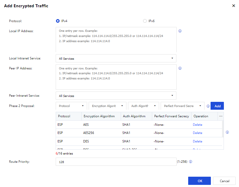
In the Others section, click Add. In the Add Encrypted Traffic dialog box, set the following parameters:
Protocol: Select IPv4 or IPv6 protocol.
Local IP Address: Enter a source IP address or IP range to match the protected data flows of IPSec VPN.
Local Intranet Service: Select a source intranet service type to match the protected data flows of IPSec VPN. You can select All Services, All TCP Services, All UDP Services, or All ICMP Services as required.
Peer IP Address: Enter a destination IP address or IP range to match the protected data flows of IPSec VPN.
Peer Intranet Service: Select a destination intranet service type to match the protected data flows of IPSec VPN. You can select All Services, All TCP Services, All UDP Services, or All ICMP Services as required.
Phase 2 Proposal: Set the parameters required for Phase 2 negotiation, including Protocol, Encryption Algorithm, Auth Algorithm, and Perfect Forward Secrecy (PFS). Options for Protocol include AH and ESP. Options for Encryption Algorithm include DES, 3DES, AES, AES192, AES256, SANGFOR_DES, and SM4. Options for Auth Algorithm include MD5, SHA1, SHA2-256, SHA2-384, SHA2-512, and SM3. You can select the Diffie-Hellman (DH) group algorithm for Perfect Forward Secrecy.
Route Priority: Set a value for local and peer IP addresses to identify the route priority.
Click OK to proceed.
- Click Advanced to configure IKE and IPSec options.
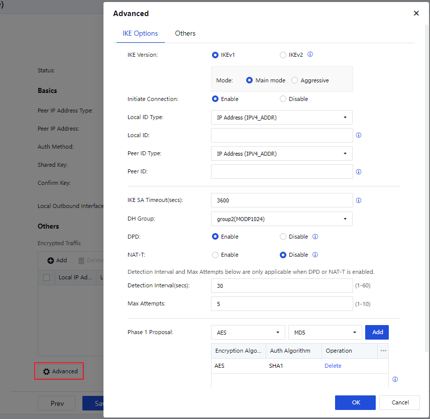
IKE Options:
IKE Version: Select IKEv1 or IKEv2. The setting must be the same as that of the peer device.
Mode: The connection mode. Options include Main mode and Aggressive. The main mode is applicable when both devices use static IP addresses, or one uses a static IP address and the other uses a dynamic domain name. It does not support NAT traversal. The aggressive mode is applicable when one of the devices establishes connections through dial-up, and it supports NAT traversal. Select either mode based on your business requirements.
Initiate Connection: Specify whether the device can actively initiate a VPN connection.
Local ID Type: Select an ID type for the local device to ensure that the peer device can identify the local device. Options include IP Address (ADDR), Domain String (FQDN), and User String (USER_FQDN).
Local ID: Set an ID for the local device based on the selected local ID type.
Peer ID Type: Select an ID type for the peer device to ensure that the local device can identify the peer device. Options include IP Address (ADDR), Domain String (FQDN), and User String (USER_FQDN).
Peer ID: Set an ID for the peer device based on the selected peer ID type.
IKE SA Timeout(secs): Set the Phase 1 lifetime for IPSec negotiation in seconds.
DH Group: Select a DH group type, including DH group 1, 2, 5, 14, 15, 16, 17, and 18. The setting must be the same as that of the peer device.
DPD: Specify whether to enable the Dead Peer Detection (DPD) feature to detect the life status of the peer device in IPSec.
NAT-T: This feature is available only in aggressive mode. It avoids failure of IPSec negotiation when NAT is enabled on one of the devices. After you enable NAT traversal, the UDP header will be added to encapsulate Encapsulating Security Payload (ESP) packets. When an ESP packet traverses a NAT device, the NAT device converts the IP address and port number in the outer IP header and the added UDP header of the packet. When the converted packet reaches the peer device of the IPSec tunnel, it is processed in the general way of the IPSec.
Detection Interval(secs): Set an interval for DPD and NAT-T detection.
Max Attempts: Set the maximum number of DPD and NAT-T detection attempts. If the number of attempts exceeds this value, the local device determines that the peer device fails and disconnects from the peer device.
Phase 1 Proposal: Set the parameters required for Phase 1 negotiation, including Encryption Algorithm and Auth Algorithm. Options for Encryption Algorithm include DES, 3DES, AES, AES192, AES256, SANGFOR_DES, and SM4. Options for Auth Algorithm include MD5, SHA1, SHA2-256, SHA2-384, SHA2-512, and SM3.
- After configuring the IKE options, click OK and then click the Others tab to configure IPSec options.
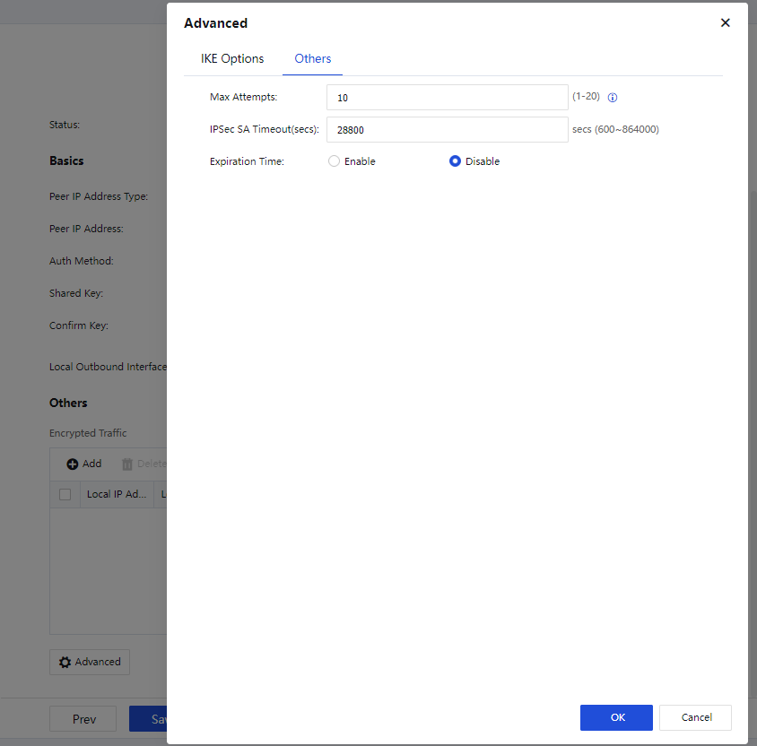
Others:
Max Attempts: Set the maximum number of attempts for IPSec VPN connection.
IPSec SA Timeout(secs): Set a timeout interval for IPSec security associations (SAs).
Expiration Time: Specify whether to enable expiration time for IPSec VPN tunnels.
Click OK to proceed.
- On the VPN Wizard (Connection to Third-Party Device) page, confirm the information and click Save.
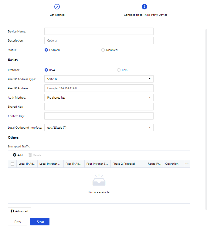
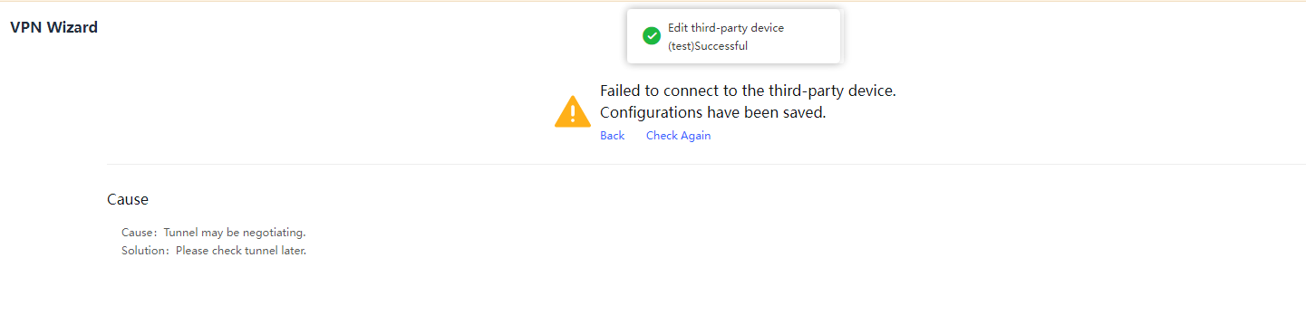
SD-WAN Configuration
SD-WAN Path Selection Templates
You can create a local SD-WAN path selection template or download one from the Branch Business Center (BBC). You can also create path selection policies for the VPN HQ device or view path selection policies for the VPN HQ and branch devices, as shown in the following figure.
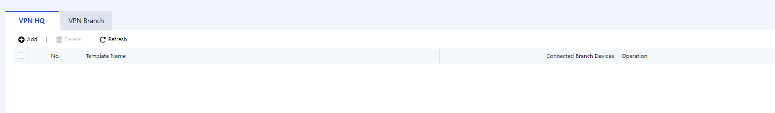
- On the VPN HQ tab, click Add. In the Add Path Selection Template dialog box, set the template name and select a branch, then click OK, as shown in the following figure.
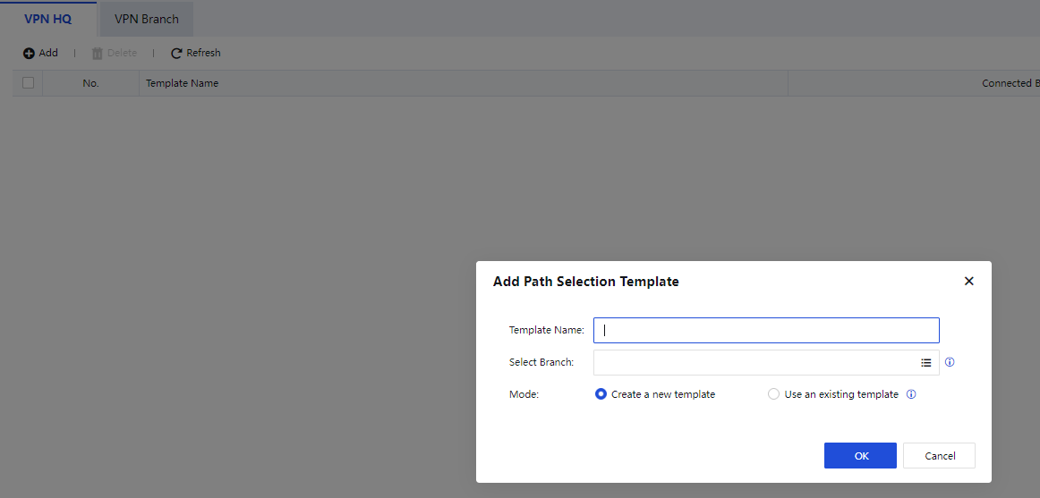
- Click Configure Path Selection Policy in the Operation column for the created template, as shown in the following figure.
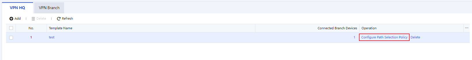
- On the page that appears, click Add, as shown in the following figure.
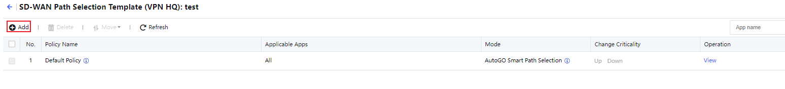
- In the Add Policy dialog box, select Specified for Mode in the App Identification section. Auto Ident is selected by default. The auto identification algorithm identifies the types and priorities of apps and automatically selects paths from them based on their service types and priorities. Herein, Specified is selected for ease of demonstration.
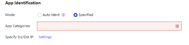
- Select apps for SD-WAN path selection in App Categories.
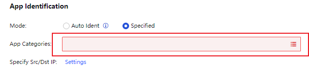
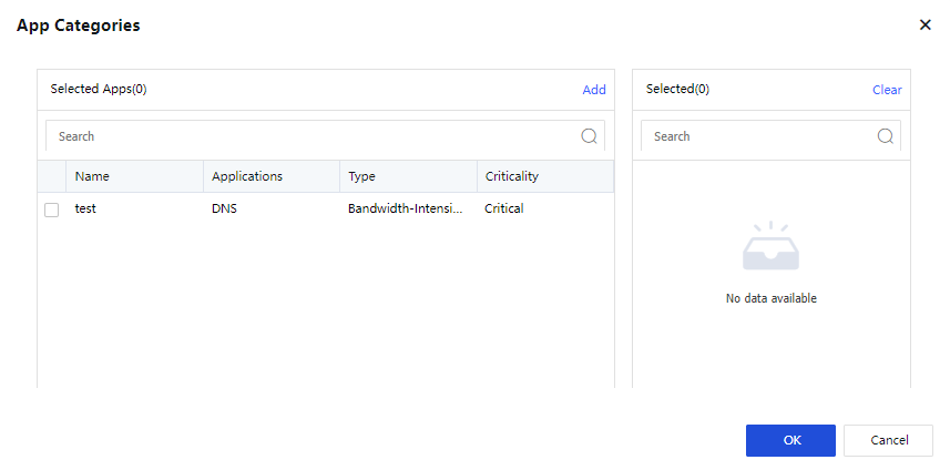
- Click Settings next to Specify Src/Dst IP and specify the IP range for SD-WAN path selection. All is selected by default.
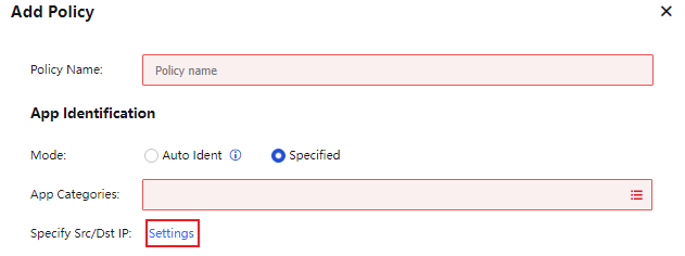
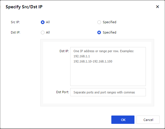
- In the Path Selection Settings section, select AutoGO Smart Path Selection for Mode and select Paths for path selection. If no paths are selected, all paths are included by default. Click OK.

Note:
The configured VPN paths are available for Local Path, and four paths are available for Peer Path by default. You can click Delete in the Operation column to delete the VPN paths that do not exist.
Notice:
If your device is not added to the BBC, you can configure SD-WAN path selection templates and policies on your local console. If your device is added to the BBC, you must configure SD-WAN path selection templates and policies on the BBC and push them down to your device. The configuration method in the BBC is the same as that in your local console.
SOFAST Optimization
SOFAST automatically identifies applications based on the Deep Packet Inspection (DPI) database and classifies them into interactive, realtime, and bandwidth-intensive categories. It intelligently detects link quality and matches link optimization models to ensure continuous business access in case of high packet loss.
Check Enable SOFAST optimization and select Adaptive or Custom for Mode, as shown in the following figure.

Adaptive: Enable SOFAST optimization based on the application packet loss rate predefined on the device.
Custom: Allow you to set a packet loss rate threshold for SOFAST optimization.
Notice:
- SOFAST optimization is available only when the transmission mode of Sangfor VPN is set to UDP, and takes effect only when it is enabled on both the HQ and branch devices.
- You can enable SOFAST optimization on the HQ and branch devices in different modes.
App Categories
The App Categories module classifies known apps into specific categories for reference in SD-WAN path selection. On the App Categories page, click Add. The Add dialog box appears, as shown in the following figure.
Type: The type of the app category, which helps identify the app category. Options include Bandwidth-Intensive App, Interactive App, and Realtime App.
Criticality: The criticality of the app category. Options include Critical, Important, Ordinary, and Noncritical.
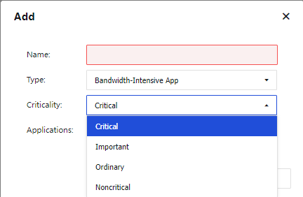
Applications: Select applications for the app identification database.
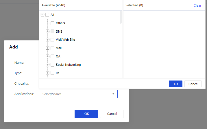
Click OK.
Notice:
If the device is added to the BBC for centralized management, you can configure app categories only in System > Application Signature Database in BBC and push down the configurations to the Network Secure device.
Sangfor VPN Configuration
Basic Settings
The Basics page contains three sections, namely Address & Secret Key, Local Subnet, and Advanced.
Address & Secret Key
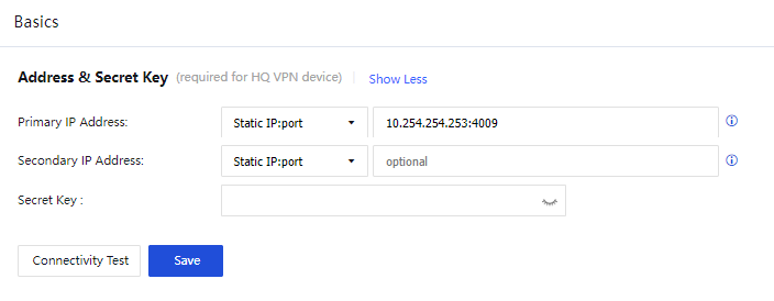
Parameters in the Address & Secret Key section:
Primary IP Address: Set a primary IP address in one of the following three formats:
Static IP:port: You can set up to four static IP addresses. Separate multiple IP addresses with pound signs (#). For example, 202.96.137.75#60.28.239.21:4009. The IP addresses are outbound IP addresses of the VPN HQ device.
Dynamic domain:port: This format is applicable when the VPN HQ device has a dynamic domain name pointing to its outbound IP address. Example: www.sangfor.com:4009.
WebAgent Server: This format is applicable when the VPN HQ device has no static IP address. For example, when Asymmetric Digital Subscriber Line (ADSL) is used, such as www.sangfor.com/NG4.0/test.php and 202.96.137.75/test.php. If you select WebAgent Server, you can set a WebAgent password that is the same as that of the WebAgent server to be accessed. Click Change Password and set a WebAgent password to prevent unauthorized users from using the WebAgent to configure fake IP addresses. The WebAgent password is optional.
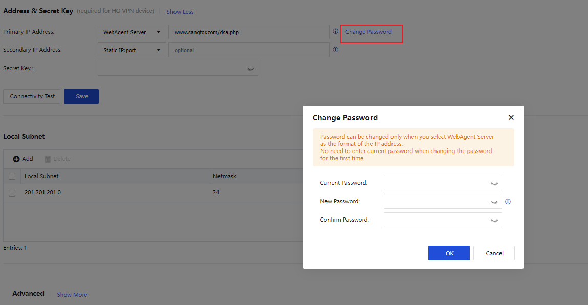
Secondary IP Address: Set a secondary IP address in the same format as the primary IP address. The matching rules are as follows:
The priority of the primary IP address is higher than that of the secondary IP address. The secondary IP address takes effect only when the primary IP address is unavailable. If you want to connect a branch device to the local device, either the primary or secondary IP address of the branch device must be the same as that of the local device.
Secret Key (Optional): The authentication password for a branch device to access the VPN HQ device. If this field is specified, you must enter the same password on the branch device to establish a VPN connection.
Connectivity Test: Check whether the format of the primary IP address is valid and whether the TCP port is accessible.
Click Save.
Notice:
- The WebAgent password cannot be restored if it is lost. You can only contact Sangfor Technical Support to generate a file without a WebAgent password and replace the original file.
- In case of multiple paths with static IP addresses, you can set WebAgent Server in the IP address 1#IP address 2:port number format.
Local Subnet
If the LAN where the device resides contains a Layer 3 switch or router and the LAN is divided into multiple subnets, you must add all the subnets other than the subnet to which the intranet interface belongs.

In the Local Subnet section, click Add. In the Add Local Subnet dialog box, enter other local subnets in IP/netmask(/priority) format, as shown in the following figure.
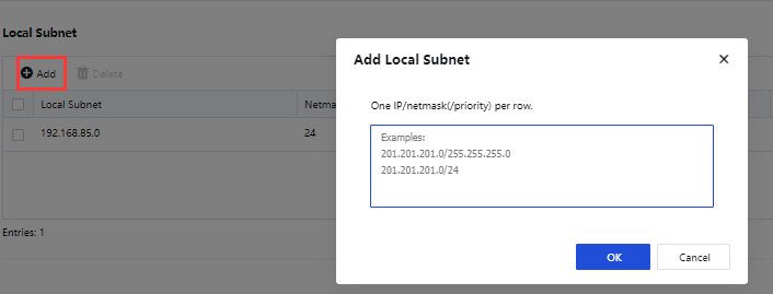
Click OK.
Notice:
The subnet to which the intranet interface belongs does not need to be added as a local subnet. You need to add other subnets as local subnets only when the LAN is divided into multiple subnets.
Advanced
In the Advanced section, the Intranet Interface, VPN Interface, and Listening Port parameters need to be configured, as shown in the following figure.
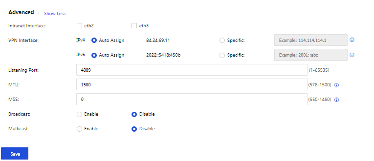
The parameters are described as follows:
Intranet Interface: Interfaces with the LAN attribute, which are used to set VPN subnets. IP addresses within the subnets of the LAN interfaces are defined as VPN data, and IP addresses in other subnets are defined as non-VPN data.
Notice:
Options for Intranet Interface include interfaces on the Network > Interfaces page that are not configured with the WAN attribute or default gateways. Interfaces with the WAN attribute will not be displayed in the Intranet Interface field.
VPN Interface: Set an IP address for the VPN interface of the local device. Two modes are available: Auto Assign and Specific.
Listening Port: Set a listening port for the VPN service as required. The default value is 4009.
MTU: Set the MTU for VPN data. The default value is 1500.
MSS: Set the MSS for VPN data in UDP mode.
Notice:
Retain the default values of MTU and MSS. If you want to modify them, contact Sangfor Technical Support representatives for instructions.
Broadcast: Specify whether to enable broadcast. If you enable broadcast, you must enter a port range for broadcast packets.
Multicast: Specify whether to enable multicast. If you enable multicast, multicast packets received from the branch LAN can be transparently transmitted to the HQ device through the Sangfor VPN tunnel. This feature takes effect only when it is enabled on both the HQ and branch devices.
Click Save for the configurations to take effect.
VPN Users
The VPN Users page shows details about VPN users, including usernames, passwords, configuration templates, and whether client certificate authentication, tunnel NAT, and multi-link policy are enabled.
To add a group, click the  icon next to All and click the Add Subgroup button. In the New Group dialog box, set the group name and click OK, as shown in the following figure.
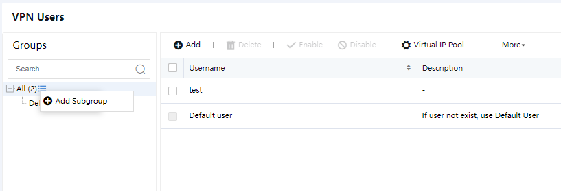
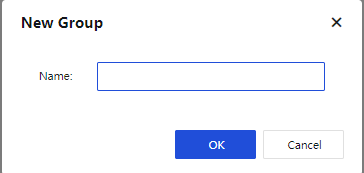
To add a VPN user, click Add above the VPN user list. In the Add VPN User dialog box, set Username, Description, Group, and other parameters, as shown in the following figure.
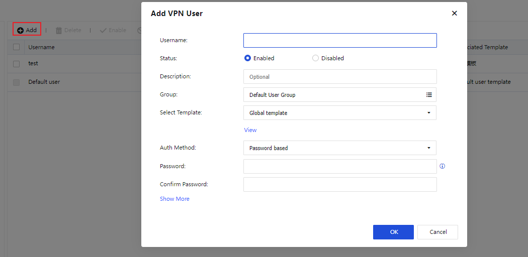
The parameters are described as follows:
Select Template: You can View the template settings or add a template to modify its content. When you add a template, set the following parameters for the template on the Add Template page: Name, Encryption Algorithm, Concurrent Login, Intranet Services, Multicast Service, and Sangfor VPN Tunnel Timeout.
Auth Method: Select an authentication method for the user. Options include Password based, Certificate based, LDAP, and RADIUS.
Advanced options include Expiration Time, Client Certificate Verification, Tunnel NAT, and Multi-link Policy.
Multi-link Policy: When the path selection policy is unavailable, you can adopt the multi-link policy to select the number of links to connect the two ends of a VPN tunnel and select primary and secondary links, as shown in the following figure.
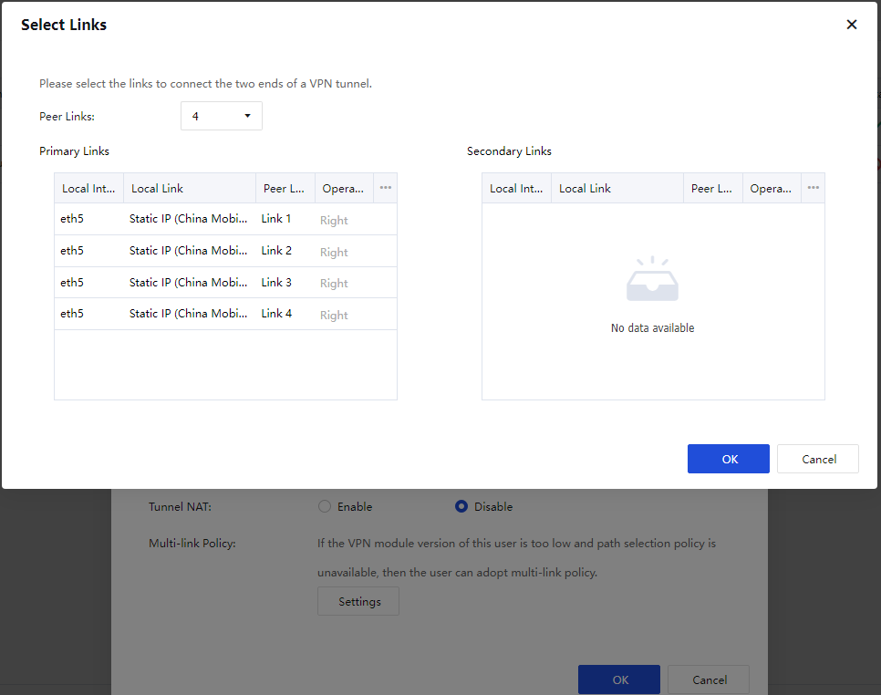
Click OK.
In the VPN user list, you can Delete, Enable, or Disable a VPN user, or select More > Move To for moving a VPN user to another group, as shown in the following figure.

You can click Virtual IP Pool to create a branch virtual IP pool. When a branch device accesses the HQ device, the original IP range of the branch device will be replaced with a virtual IP range in the branch virtual IP pool to avoid conflict when two branch devices with the same IP range access the HQ device. In the Virtual IP Pool dialog box, set Start IP address/Netmask, Subnets, and Description for the virtual IP pool, as shown in the following figure.
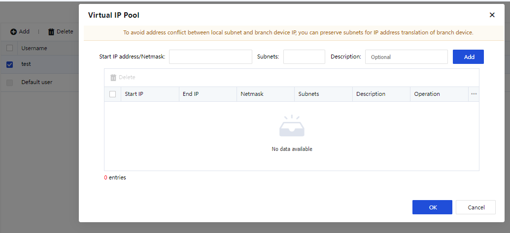
Click OK.
You can click More and choose Import to import users from a local CSV or TXT file or users authenticated by a third-party server. After users are imported, the system will display a corresponding prompt.
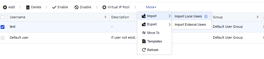
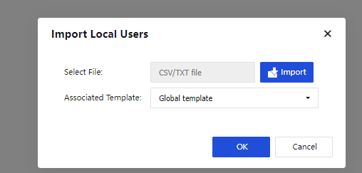
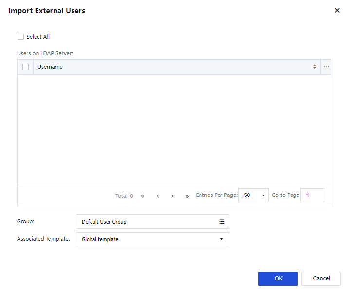
You can click More and choose Export > Export VPN Users to export users to your local computer. Passwords of the exported users are displayed in Ciphertext, as shown in the following figure.
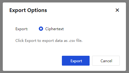
You can click More and choose Templates to manage the configuration templates for VPN users, as shown in the following figure.
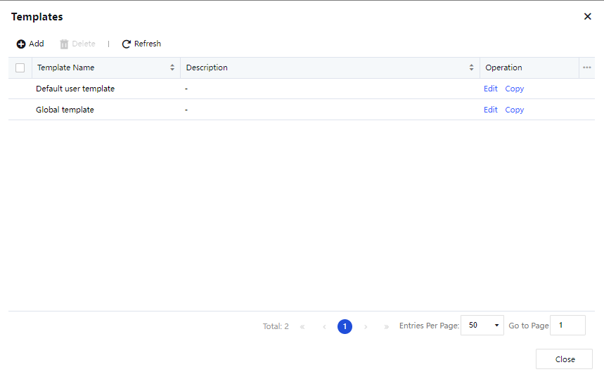
You can add a template. In the Templates dialog box, click Add and set Encryption Algorithm, Intranet Services, Multicast Service, and other parameters for the template.
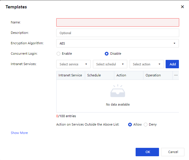
Click OK. The template appears in the template list.
Tunnel NAT
Tunnel NAT is intended to avoid conflict between subnets of branch devices. To enable tunnel NAT on the HQ device, click Virtual IP Pool on the VPN Users page, as shown in the following figure.
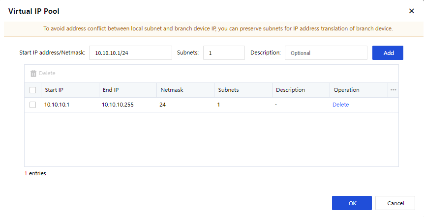
In the Add VPN User dialog box, you can specify whether to enable Tunnel NAT, as shown in the following figure.
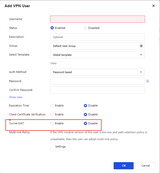
If you select Enable for Tunnel NAT, you must set a source subnet. You can specify whether to enable Auto Assign. If you select OK, the system automatically assigns virtual IP addresses. If you select Cancel, you must manually add virtual IP addresses. If no IP address is available in the virtual IP pool, click Virtual IP Pool on the VPN Users page to create a pool.
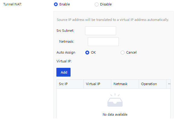
Click OK.
VPN Connection
To connect multiple network nodes to form a mesh network, the VPN gateway allows you to manage and configure the connections between network nodes. You can perform related operations on the VPN Connection page, as shown in the following figure.

Notice:
This feature is required only when a branch device needs to access other Sangfor devices. If the local device is a VPN HQ device, you do not need to enable this feature.
You can add a connection from the local device to a VPN HQ device. On the VPN Connection page, click Add, as shown in the following figure.

The parameters are described as follows:
HQ Device and Description: Used to identify and describe the connection. You can set them as required.
Shared Key, Username, and Password: Set these parameters based on the VPN user information provided by the HQ device.
Primary IP Address and Secondary IP Address: Indicate the IP addresses and ports of the HQ devices to be accessed. You can click Connectivity Test to check whether the IP addresses are accessible.
Note:
If the IP address is a domain name, the success of the connectivity test indicates that the webpage exists; otherwise, the webpage does not exist. If the IP address is a static IP address, the success of the connectivity test indicates that the format of the IP address is valid (IP address:Port number). The success of the connectivity test does not guarantee the success of the VPN connection.
Protocol: Indicate the protocol for encapsulating VPN packets. Options include UDP, UDP with pseudo TCP header, and UDP with pseudo ESP header. UDP is selected by default. TCP has been removed from the current version.
Note:
In UDP with pseudo TCP header mode, the TCP header is added to UDP packets so that the packets look like TCP packets and support NAT traversal. However, no three-way handshake is performed in TCP NAT traversal, and the internet service providers (ISPs) can still block the packets. In UDP with pseudo ESP header mode, the ESP header is added to UDP packets so that the packets look like ESP packets and support NAT traversal. However, the NAT traversal can be identified by ISPs and fails.
VPN Connection Auto Recovery: In this section, you can enable periodic VPN port switching and auto protocol switching to alleviate the VPN problems caused by port and protocol blocking by ISPs, as shown in the following figure.
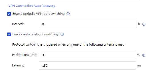
Enable periodic VPN port switching: If you enable this feature, the VPN will establish a VPN connection by using the new port within the specified interval. In this case, the old and new VPN connections coexist. The old VPN connection is destructed after your business is handed over to the new VPN connection.
Enable auto protocol switching: If you enable this feature, three redundancy connections will be created based on UDP, FAKE_TCP, and FAKE_ESP when you establish a VPN connection for a Sangfor VPN tunnel. When the primary connection fails or degrades beyond the preset criteria, it will be switched to one of the other two connections with the best quality.
Click Show More to set permissions for the VPN peer device, specify the local services accessible to the VPN peer device, as shown in the following figure.
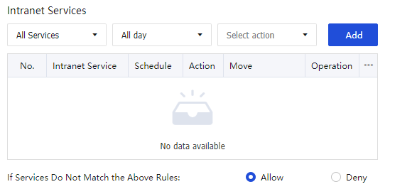
Click Add to add the intranet services. Then click OK to activate the connection and save the settings.
Advanced
The Advanced page contains Tunnel Route, Multicast Services, Schedules, Third-Party Auth Server, RIP, and Client Certificate tabs.
Tunnel Route
Network Secure allows you to configure routes between VPN tunnels to easily connect multiple VPNs (software/hardware) to form a mesh VPN network.
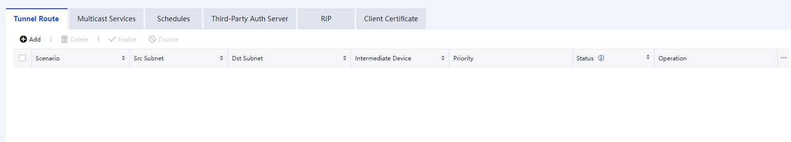
You can click Add on the Tunnel Route tab to add a tunnel route. The Add Tunnel Route dialog box appears, as shown in the following figure.
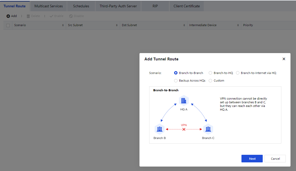
Scenario: Tunnel routes are applied to the following five scenarios:
Branch-to-Branch: If both branch devices B and C are connected to HQ device A, you can configure a tunnel route to enable communication between branch devices B and C via HQ device A.
Branch-to-HQ: If branch device C is connected to secondary HQ device B, you can configure a tunnel route to enable communication between branch device C and primary HQ device A via secondary HQ device B.
Branch-to-Internet via HQ: If branch device B has no outbound interface to the internet but is connected to HQ device A, you can configure a tunnel route to allow intranet users of branch device B to access the internet via HQ device A.
Backup Across HQs: It is assumed that branch device C can access a business system C via either HQ device A or B. Generally, branch device C accesses the business system C via HQ device A. When branch device C is disconnected from HQ device A, it can access the business system C via HQ device B.
Custom: In other scenarios, you can configure tunnel routes based on your business requirements.
For example, Branch-to-Branch is selected. Click Next.
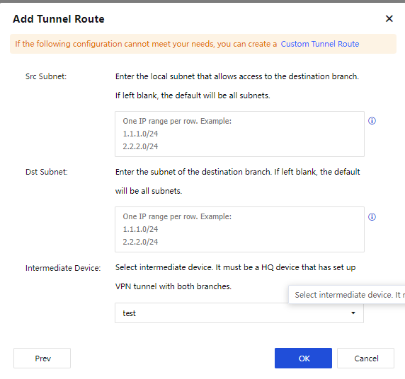
The parameters are described as follows:
Src Subnet: Set source IP ranges and netmasks for the tunnel route.
Dst Subnet: Set destination IP ranges and netmasks for the tunnel route.
Intermediate Device: Select a VPN tunnel for the tunnel route. For example, a VPN connection is established between devices A and B by using user "A". If device A wants to access device C via device B, the VPN tunnel for device A is user "A".
Click OK to enable the tunnel route.
Notice:
- When branch-to-internet via an intermediate device is enabled, the remote VPN branch device must be deployed in gateway mode, and the local device can be deployed in either gateway or single-arm mode.
- Before you create a tunnel route, make sure that a VPN user has been created for the VPN device on the VPN Users page or a VPN connection has been created for the VPN device on the VPN Connection page.
- Options for Intermediate Device include users with Concurrent Login disabled when templates were configured for them on the VPN Users page and users configured on the VPN Connection page (excluding those with duplicate names or disabled).
Multicast Services
Sangfor devices support transmission for multicast services across tunnels to adapt to VoIP and video conference apps. The IP range and port range available for multicast services are 224.0.0.1-239.255.255.255 and 1-65535, respectively. You can define multicast services on the Multicast Services tab, as shown in the following figure.
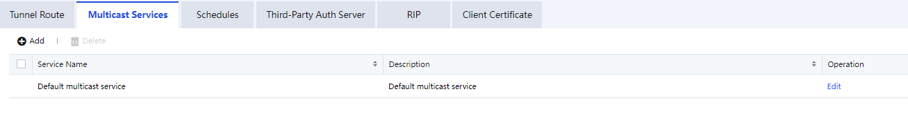
Click Add to enter the Add Multicast Service page. In IP Range, click Add, and the Add IP Range dialog box will appear. You can set an IP range and a port range for the multicast service, as shown in the following figure.
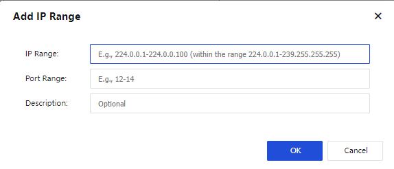
After defining the multicast service, go to the VPN Users page and click Add. In the Add VPN User dialog box, click Add for Select Template. In the Add Template dialog box, select Enable for Multicast Service and add multicast services, as shown in the following figure.
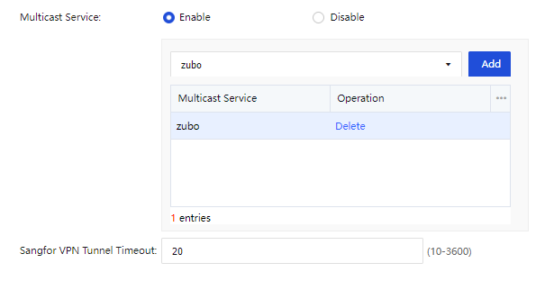
Schedules
You can define common schedules and apply them to intranet services when you add a template on the VPN Users page. The schedules work based on the current system time on the device, as shown in the following figure.

On the Schedules tab, click Add. The Schedule dialog box appears, as shown in the following figure.
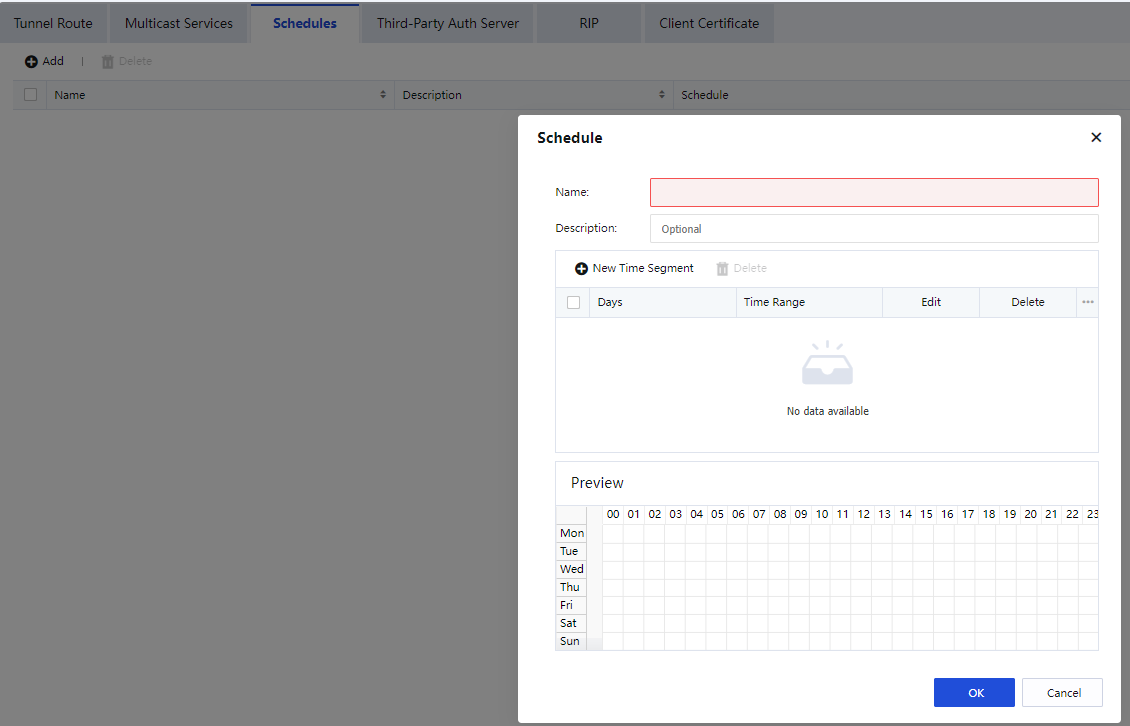
Set the schedule name to test and select time segments. The time segments highlighted in blue are effective, and others are not. Click OK.
On the VPN Users page, click More and choose Templates. In the Templates dialog box, click Add. In the next Templates dialog box, select the schedule for Intranet Services, as shown in the following figure.
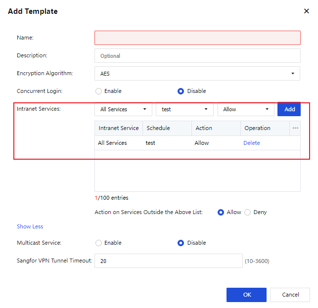
Third-Party Auth Server
LDAP Server
The VPN service of Sangfor devices supports third-party LDAP authentication. If you want to enable third-party LDAP authentication, configure information about the third-party LDAP server on the LDAP Server page, including Server IP, Server Port, and Admin Password, as shown in the following figure.
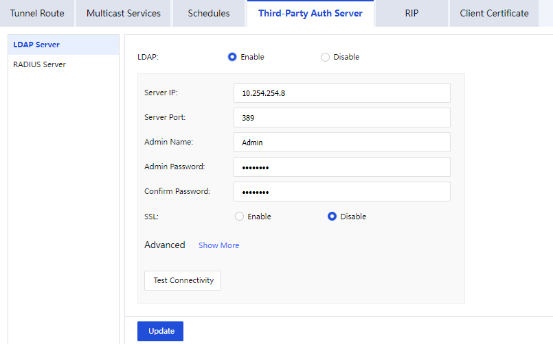
Click Show More next to Advanced and configure the advanced options as required, as shown in the following figure.
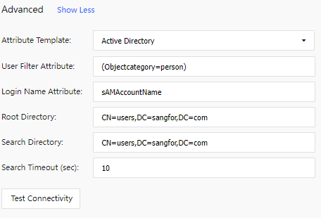
RADIUS Server
The VPN service of Sangfor devices supports third-party LDAP authentication. If you want to enable third-party RADIUS authentication, configure information about the third-party RADIUS server on the RADIUS Server page, including Server IP, Server Port, Shared Key, and Protocol, as shown in the following figure.
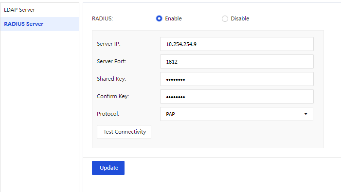
RIP
You can enable Routing Information Protocol (RIP) to allow a Sangfor device to advertise routing information to other routers so that routing information on intranet routers can be dynamically updated, as shown in the following figure.
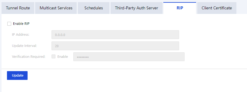
The parameters are described as follows:
Enable RIP: Specify whether to enable dynamic route updates based on RIP. If you check Enable RIP, the Sangfor device will advertise information about the peer device that has established a VPN connection to the local device to the specified intranet router. The routing tables of other devices are updated, and a route from the VPN peer device to the Sangfor device is added. If the VPN connection fails, the router is instructed to delete the route.
IP Address: Enter the IP address of the router to which route updates will be advertised.
Update Interval: The interval for route updates. The Sangfor device will trigger a route update when the route changes. In this case, this parameter does not take effect.
Verification Required: Specify whether a password is required for exchanging RIP packets.
Client Certificate
The certificate authentication system based on hardware features is one of Sangfor’s patented inventions. Sangfor devices also use this technology for authentication among VPN nodes. The client certificate of a Sangfor device is an encrypted certificate generated based on the hardware features of the device. The client certificate is unique and unforgeable because of the uniqueness of the device’s hardware features. The hardware features are verified so that only the specified device is authorized to access the network. This helps avoid security risks.
You can click Client Certificate to generate a client certificate and store it on your local computer, as shown in the following figure.
Send the client certificate to the HQ device administrator. When you add a VPN user, the HQ device administrator can select the client certificate for authentication and bind the user to the client certificate.
IPSec VPN Configuration
Network Secure supports IPSec VPN connections to third-party devices. IPSec VPN of Network Secure conforms to the international IPSec VPN protocol. Provided that the peer device also adopts the standard IPSec VPN, you can establish a VPN connection between the local device and the peer device.
You can click Add Connection on the IPSec VPN Configuration page to add IPSec VPN connections. The Add Connection dialog box appears, as shown in the following figure.
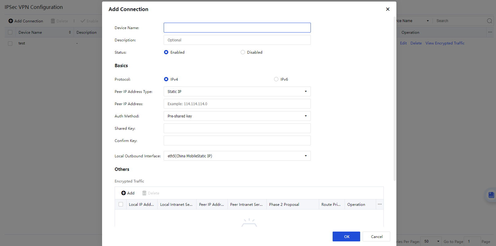
The parameters are described as follows:
Device Name: Set a name for the tunnel.
Status: Specify whether to enable the VPN connection.
Description (Optional): Enter a description of the tunnel.
Peer IP Address Type: Select Static IP, Dynamic IP, or Dynamic Domain as required. If you select Static IP, enter the IP address of the peer device. If you select Dynamic Domain, enter the WAN domain name of the peer device.
Auth Method: Select Pre-shared key, Certificate based, or SM2 Certificate V1.1 as required.
Shared Key and Confirm Key: Enter the correct pre-shared key. Ensure that both devices use the same pre-shared key.
Local Outbound Interface: Select an outbound interface based on the link status.
Encrypted Traffic: Set parameters for protected data flows and Phase 2 negotiation of IPSec VPN as required.
Click Add in the Encrypted Traffic section. The Add Encrypted Traffic dialog box appears, as shown in the following figure.
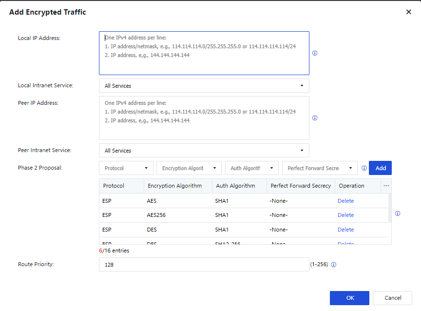
The parameters are described as follows:
Local IP Address: Enter a source IP address or IP range to match protected data flows of IPSec VPN.
Local Intranet Service: Select a source intranet service type to match protected data flows of IPSec VPN. You can select All Services, All TCP Services, All UDP Services, or All ICMP Services as required.
Peer IP Address: Enter a destination IP address or IP range to match protected data flows of IPSec VPN.
Peer Intranet Service: Select a destination intranet service type to match protected data flows of IPSec VPN. You can select All Services, All TCP Services, All UDP Services, or All ICMP Services as required.
Phase 2 Proposal: Set the parameters required for Phase 2 negotiation, including Protocol, Encryption Algorithm, Auth Algorithm, and Perfect Forward Secrecy (PFS). Options for Protocol include AH and ESP. Options for Encryption Algorithm include DES, 3DES, AES, AES192, AES256, SANGFOR_DES, and SM4. Options for Auth Algorithm include MD5, SHA1, SHA2-256, SHA2-384, SHA2-512, and SM3.
Route Priority: Set a priority for local and peer IP addresses to identify the route priority.
Click Advanced to configure IKE and IPSec options, as shown in the following figure.
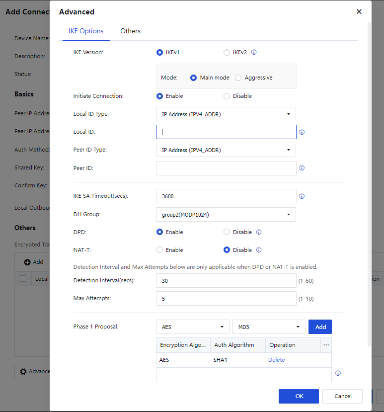
IKE Options:
IKE Version: Select IKEv1 or IKEv2. The setting must be the same as that of the peer device.
Mode: The connection mode. Options include Main mode and Aggressive. The main mode is applicable when both devices use static IP addresses or one uses a static IP address and the other uses a dynamic domain name. It does not support NAT traversal. The aggressive mode is applicable when one of the devices establishes connections through dial-up, and it supports NAT traversal. Select either mode based on your business requirements.
Initiate Connection: Specify whether the device can actively initiate a VPN connection.
Local ID Type: Select an ID type for the local device to ensure that the peer device can identify the local device. Options include IP Address (ADDR), Domain String (FQDN), and User String (USER_FQDN).
Local ID: Set an ID for the local device based on the selected local ID type.
Peer ID Type: Select an ID type for the peer device to ensure that the local device can identify the peer device. Options include IP Address (ADDR), Domain String (FQDN), and User String (USER_FQDN).
Peer ID: Set an ID for the peer device based on the selected peer ID type.
IKE SA Timeout(secs): Set the Phase 1 lifetime for IPSec negotiation in seconds.
DH Group: Select a DH group type, including DH group 1, 2, 5, 14, 15, 16, 17, and 18. The setting must be the same as that of the peer device.
DPD: Specify whether to enable the Dead Peer Detection (DPD) feature to detect the life status of the peer device in IPSec.
NAT-T: This feature is available only in aggressive mode. It avoids failure of IPSec negotiation when NAT is enabled on one of the devices. After you enable NAT traversal, data will be encapsulated based on UDP instead of ESP, in case ESP is not allowed on the intranet.
Detection Interval(secs): Set an interval for DPD and NAT-T detection.
Max Attempts: Set the maximum number of DPD and NAT-T detection attempts. If the number of attempts exceeds this value, the local device determines that the peer device fails and disconnects from the peer device.
Phase 1 Proposal: Set the parameters required for Phase 1 negotiation, including Encryption Algorithm and Auth Algorithm. Options for Encryption Algorithm include DES, 3DES, AES, AES192, AES256, SANGFOR_DES, and SM4. Options for Auth Algorithm include MD5, SHA1, SHA2-256, SHA2-384, SHA2-512, and SM3.
After configuring the IKE options, click OK and then click the Others tab to configure the IPSec options.
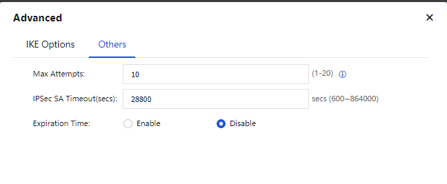
Others:
Max Attempts: Set the maximum number of attempts for IPSec VPN connection.
IPSec SA Timeout(secs): Set a timeout interval for IPSec security associations (SAs).
Expiration Time: Specify whether to enable expiration time for IPSec VPN tunnels.
Click OK to save the settings. In the Operation column, you can click Edit to modify the parameters of the VPN connection or click View Encrypted Traffic to view the matching rules for encrypted traffic.
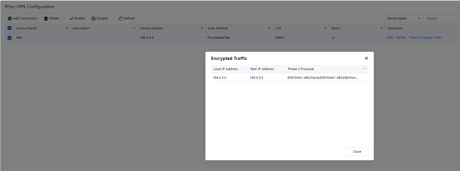
General Settings
VPN Paths
If multi-link licensing is enabled for the device, multiple WAN interfaces are configured. In this case, you can add multiple VPN paths on the VPN Paths page. On the VPN Paths page, click Add. The Add VPN path dialog box appears, as shown in the following figure.
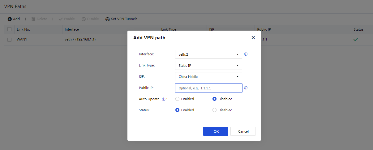
The parameters are described as follows:
Interface: Select a WAN interface.
Link Type: Select a preset link type or click Add to create one, as shown in the following figure.
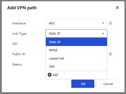
ISP: Select a preset ISP or click Add to create one, as shown in the following figure.
Public IP: Enter a public IP address.
Auto Update: Specify whether to enable auto updates for the public IP address. In a dial-up scenario, you can enable this feature to automatically obtain the public IP address of the outbound interface. If you want to manually set the public IP address, select Disabled so that the public IP address is not automatically updated.
Click OK. The VPN path appears in the VPN path list.
Set VPN Tunnels
You can select local and peer links to establish Sangfor VPN connections. Unselected links cannot be used for establishing Sangfor VPN connections. This avoids Sangfor VPN connections across ISPs or link types. For example, link 1 for the HQ device and link 1 for the branch device are private links of China Telecom, and link 2 for the HQ device and link 2 for the branch device are internet links of China Telecom. In this case, only two Sangfor VPN connections are allowed between the HQ and branch devices: a Sangfor VPN connection between their private links, and a Sangfor VPN connection between their internet links.
Click Set VPN Tunnels on the VPN Paths page. The Set VPN Tunnels dialog box appears, as shown in the following figure.

If you check Set up VPN tunnels through specified paths, you must set the number of peer links and select local and peer links.
For example, set Peer Links to 4. In the Available Paths section, you can click Right in the Operation column to move the VPN paths to the Selected Paths section. The VPN paths in the Selected Paths section can be used for establishing Sangfor VPN connections. For example, the GE3 Private link (China Telecom) Link 2 and GE4 Internet static IP (China Telecom) Link 4 are moved to the Selected Paths section, as shown in the following figure.
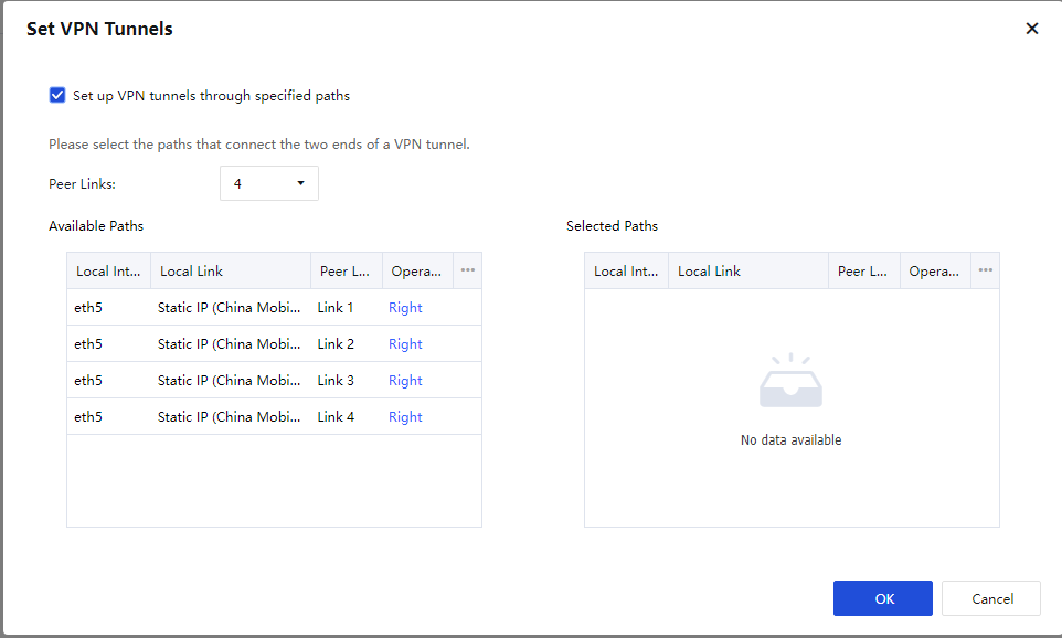
Click OK.
CSR
Navigate to Network > Sangfor/IPSec VPN > General Settings > Certificate Request. On the CSR page, click Add to enter the Add CSR dialog box, as shown in the following figure.
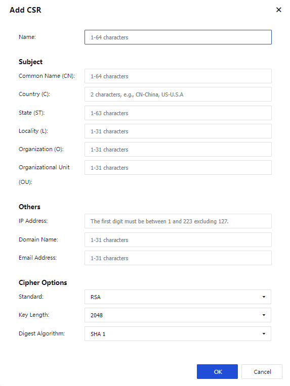
The parameters are described as follows:
Name and parameters in the Subject and Others sections: Set the parameters based on your requirements.
Standard: You can select RSA.
Key Length: Options include 1024, 2048, and 4096.
Digest Algorithm: Options include SHA 1 and SHA 2.
Click OK. A CSR file and a key file will be generated. You can click Download to download the CSR file. Only offline Certificate Signing Requests (CSRs) are supported.
Certificates
You can manage certificates on the Certificates page, as shown in the following figure.
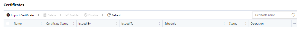
You can click Import Certificate to import an offline certificate, as shown in the following figure.
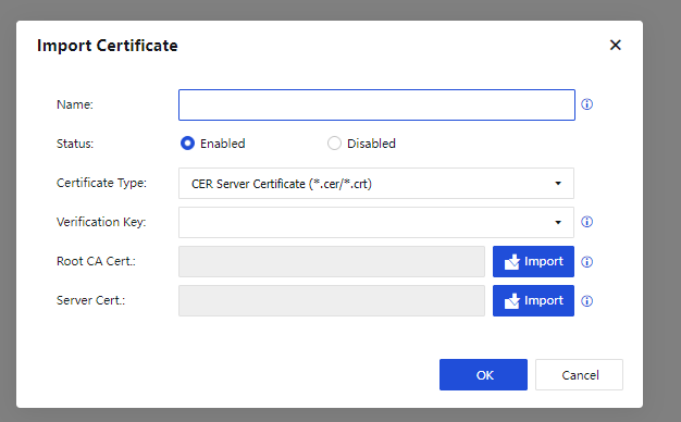
The parameters are described as follows:
Name: Set a name for the certificate as required.
Status: Specify whether to enable the certificate.
Certificate Type: Options include CER Server Certificate (*.cer/*.crt), CER Root Certificate (*.cer/*.crt), PKCS#12 (*.pfx/*.p12), PKCS#7 (*.p7b), PKCS#7 Encryption Certificate (*.p7b), and Signature & Encryption Certificates (*.cer/*.crt).
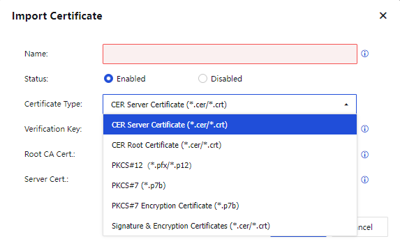
If you select CER Server Certificate (*.cer/*.crt), the Verification Key comes from the request list. You must select the request corresponding to the certificate to be imported, as shown in the following figure.
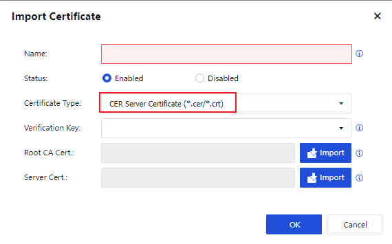
If you select CER Root Certificate (*.cer/*.crt), the dialog box appears as follows:
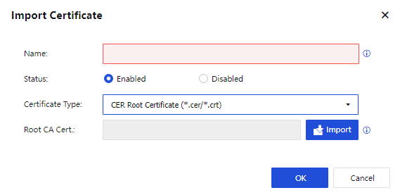
If you select PKCS#12 (*.pfx/*.p12), the password is the same as that you entered when the certificate was exported or generated. The certificate can be imported only when the root certificate and password are correct, as shown in the following figure.
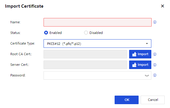
If you select PKCS#7 (*.p7b), the Verification Key comes from the request list. You must select the request corresponding to the certificate to be imported, as shown in the following figure.
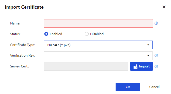
If you select PKCS#7 Encryption Certificate (*.p7b), the Verification Key comes from the request list. You must select the request corresponding to the certificate to be imported. In addition, you must import the encryption certificate and private key file, as shown in the following figure.
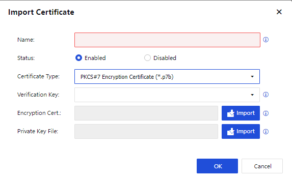
If you select Signature & Encryption Certificates (*.cer/*.crt), the Verification Key comes from the request list. You must also import the root certificate, level 1 CA certificate, signature certificate, encryption certificate, and private key, as shown in the following figure.
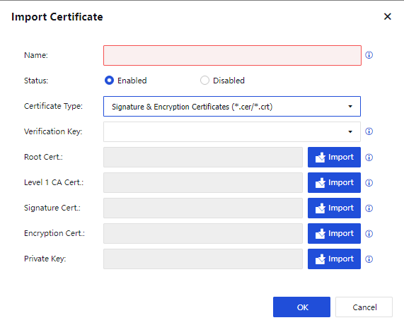
Click OK. The certificate appears in the certificate list. You can edit and download it, as shown in the following figure.
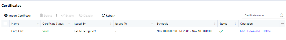
Note:
If the certificate is a root certificate, you can download a CA root certificate. If the certificate is a non-root certificate, you can download a CA root certificate or PKCS#12 certificate (.pfx/.p12).
Intranet Services
Sangfor devices allow you to specify access permissions for VPN users so that a specific IP address or branch user on the intranet can access only specific computers and service parameters. You can also use the path selection policy to identify apps based on 5-tuple defined in the intranet services.
You can configure intranet services to control service access and app identification, which enables security management for VPN tunnels and allows you to specify different path selection policies for different apps, as shown in the following figure.
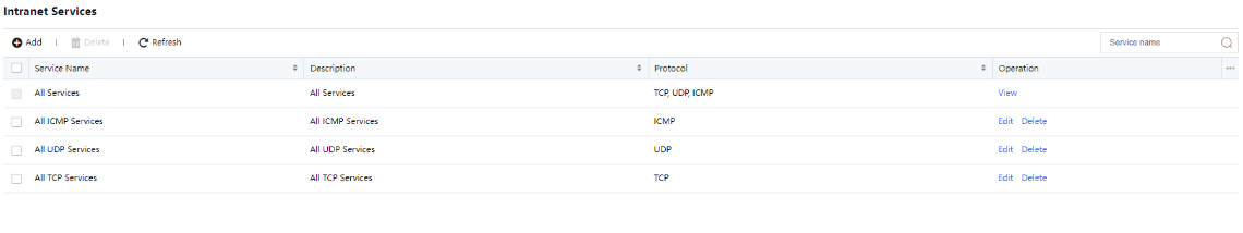
You can add intranet services by protocol type. On the Intranet Services page, click Add. The Add Intranet Service dialog box appears, as shown in the following figure.
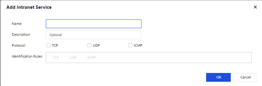
The parameters are described as follows:
Name and Description: Enter a name and a description for the intranet service, which helps manage the intranet service.
Protocol: Select a protocol used by the intranet service.
If you select TCP or UDP, click Add and set the source IP range, source port range, destination IP range, and destination port range, as shown in the following figure.
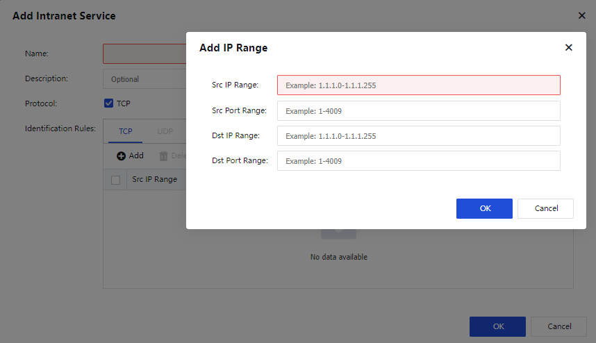
If you select ICMP, click Add and set the source IP range and destination IP range, as shown in the following figure.
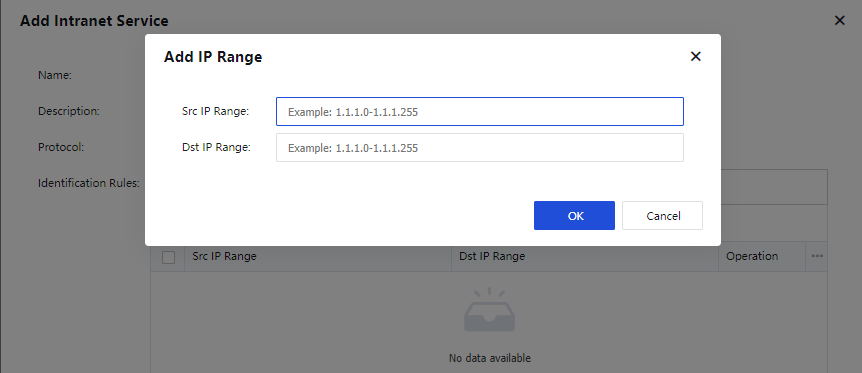
Click OK to save the settings.
Logs
On the Logs page, you can download logs and set the capacity of logs, including the number of logs to be preserved and the log size. The maximum log size allowed is 10 MB.
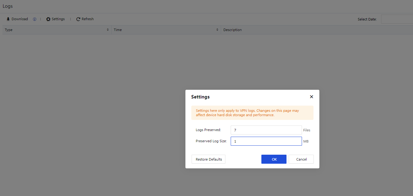
You can click Filter to set filter criteria for logs, including the username, HQ device, third-party device, peer IP address, and log type. To properly display VPN negotiation logs, you must select the corresponding log type.
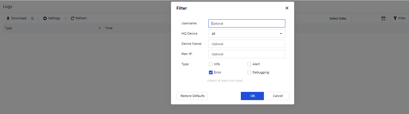
You can click Download to download VPN logs and save them to your local computer, as shown in the following figure.
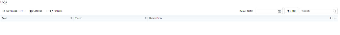

System
To set system functions and parameters. It includes security capability update, general configuration, troubleshooting, SNMP, admin account, system maintenance, high availability, and other functional modules.
General Settings
The General Settings module includes the following tabs: Web UI, Network, Email & SMS Server, System Time, NTP Key, Hosts, Licensing, OOBM, and Privacy Options.
Web UI
Web UI: Specify parameters in the Web UI Options and Login Security sections.
In the Web UI Options section, set the Device Name, HTTPS Ports, Idle Timeout (mins), etc., as shown in the following figure.
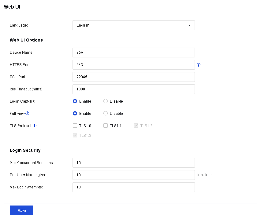
Language: Support switch between Chinese and English.
Danger:
When switching between English and Chinese, the console will restart because of changes to the global configuration. This will trigger an automatic logout and a page refresh. As databases are also switched (services are not disrupted), you need to wait 5-10 minutes before logging in again. Do not switch languages frequently. When language switching is necessary, schedule a suitable time.
Device Name: Specify the name of the device.
HTTPS Port: Specify the port by which you log in to the console. By default, this parameter is set to port TCP 443.
SSH Port: Specify the port by which you log in to the console via Secure Shell (SSH). By default, this parameter is set to TCP port 22345.
Idle Timeout (mins): Specify the timeout for the console. If the administrator does not operate the console within the specified time, the system is automatically disconnected.
Login Captcha: Specify whether to enable the option of Login Captcha when you log in to the console.
Full View: Specify whether to enable the Full View option when you log in to the console. After this option is enabled, when you access the page that can refresh automatically, you will not be forced to log out due to the timeout. It is recommended to enable this option when you need to project the page to a large screen for monitoring security information.
TLS Protocol: Specify the browser TLS protocol that is available for the console. This protocol determines whether you can log in to the Network Secure console using the browser.
Max Concurrent Sessions: Specify the maximum number of users allowed to log in to the console simultaneously.
Per-User Max Logins: Specify the number of IP addresses using an identical admin account to log in to the device console.
Max Login Attempts: Specify the number of login failures allowed for an administrator.
Click Save. Then, the configuration takes effect.
Network
On the Network page, you can set the parameters related to the global network.
Network Parameters
TCP Conn Timeout (secs), UDP Conn Timeout (secs), and ICMP Timeout (secs): Specify the timeout for TCP, UDP, and ICMP connections. When no new packets are generated within the specified time, the connection is considered time out and therefore disabled.
FTP Port, RTSP Port, SQLNET Port, TFTP Port, and PPTP Port: Specify protocol ports. If the device should serve as an application-layer proxy of these protocols in the network and the ports are not the default ones, the port information should be modified.
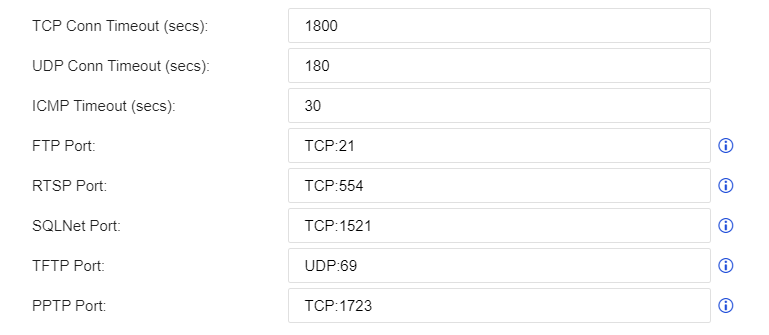
Management Interface
IP Address: Specify the default IP address of the management interface.
Peer IP Address: Specify the peer IP address for accessing the Network Secure device through the management interface.
Access Control: After you select Enable for this parameter, the source IP addresses that access 10.251.251.251, the device’s super management IP address, are only allowed to access the IP address set for the Peer IP Address parameter.
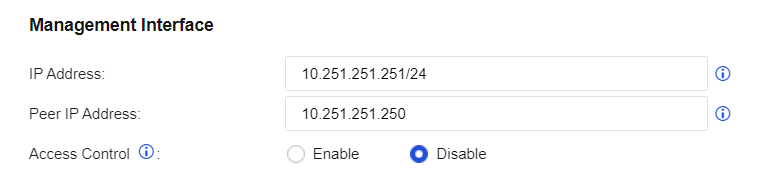
VLAN 0 IP
VLAN 0 IP: Specify the IP address for the Network Secure device to redirect some pages.
Web Auth IP: Specify the IP address for Network Secure that enables user authentication to redirect to the authentication page.
H.323 Port
RAS: Specify the port of RAS. By default, this parameter is set to UDP port 1719.
Q931: Specify the port of Q931. By default, this parameter is set to TCP port 1720.
SIP Port
Session Initiation Protocol Port: Specify the port of the SIP. By default, this parameter is set to UDP port 5060 and TCP port 5060.
Gratuitous ARP
ARP Broadcast Interval (secs): Specify whether to enable the free ARP broadcast and the interval for regularly sending the free ARP broadcast. It is recommended to enable this parameter. To avoid excessive gratuitous ARPs, the default interval is 30 seconds.
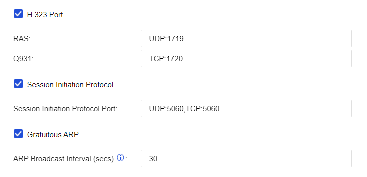
Route Priority Settings
Route Priority Settings allows you to customize the priorities of the device’s internal routes. The default priorities are shown in the following figure.
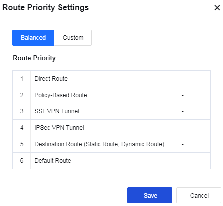
Home, Business Asset, and User Security Page Display Settings
Specify the display mode of the home page, business asset security page, and user security page. Cached Mode (Recommended) and Realtime Mode are available.
Advanced Settings
Send a TCP Reset message to deny a request: Specify whether to send the TCP reset message and disconnect data connections denied by the device policy.
Detect abnormal packets: When this feature is selected, drop abnormal TCP messages. To prevent losing normal TCP messages, do not enable this feature for deployment (e.g., asymmetric routing) requiring no special attention to the TCP status.

Send a TCP Reset message in mirror mode to deny request: Specify whether to allow the device to send the TCP reset message in mirror mode.
Enable Base64 decoding: Specify whether Web App Protection performs a security check on base64 data.
Check Base64 error: Specify whether Web App Protection performs security checks on non-compliant Base64-encoded data.
Enable IPv4/IPv6 support: Enable Network Secure to support IPv4/IPv6 dual protocol stack. To enable this function, you must restart the device.
Enable high performance for internet access: Only available for users in the Internet access scenario. Enabling this function in the case of performance bottlenecks can promote system throughput.
Respond to MAC address change of network neighborhood: Speed up the response to the changes in the MAC address of the network neighborhood. It is recommended to enable this function in the case of such changes.
Visible to Linux with traceroute command: Already supported in the Windows system by default. This function is only available in the Linux system. When it is enabled, the gateway is visible to the tracing route in the Linux system. For gateway security reasons, this function is disabled by default.
Enable network load balancing on network adapter: Can perform software load distribution to improve performance of the whole device, when the traffic contains a large amount of identical quintuple data including source IP address, source port, destination IP address, destination port, and transmission-layer protocol.
Enable inbound DoS protection: When checked, the Inbound Attack Protection option is available on Policies > Network Security > Anti-DoS/DDoS.
Allow associating policy-based routes with applications: Specify whether to allow associating policy-based routes with applications.
Bypass application layer detection: When business traffic reaches the device’s performance limit, checking this option allows certain traffic to bypass security checks to ensure network stability. This function is enabled by default.
Enable body identification: Determine the data type according to the body content.
Enable smart scan for internet access scenarios: If enabled, Engine Zero will perform a smart scan to speed up the scan process and offload traffic more efficiently.
Enable application control based on domain name: When you select this option, the system supports domain name-based control of the application control policy.
Enable body identification: Judge the data type according to the body content.
Allow associating policy-based routes with applications: Specify whether to associate the policy-based routing with applications.
Allow modifying interface count in HA mode: If the number of interfaces on HA nodes is inconsistent, you can enable this feature and go to System > High Availability > Physical Interfaces to change the number of interfaces. Please disable this feature after you complete the change.
Disable TCP connection reuse: A new connection will be opened for subsequent sessions that have the same 5-tuple (source/destination IP address, source/destination port, and protocol). TCP connection reuse is enabled by default.
On the Email & SMS Server tab, you can configure the information about the Email & SMS Server the device uses to send alarm emails.
Email Server
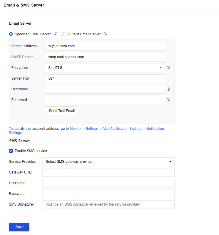
Specified Email Server: Use the specified email server to send email instead of the build-in email server. For example, Gmail or Outlook SMTP server.
Built-in Email server: Use Sangfor’s sender email address and Email & SMS Server. By default, the email is encrypted by SSL, and the port is port 465 for SMTPS.
Sender Address: Specify the email address the device uses to send alarm emails.
SMTP Server: Specify the Email & SMS Server’s domain name or IP address corresponding to the sender’s email address.
Encryption: There are three options for encryption: None, SSL, and StartTLS.
Server Port: Specify the Email & SMS Server port.
Username: You can enter the sender’s email address or username.
Password: If the sender’s email address has enabled the third-party client authorization code, enter the authorization code in the field.
After you enter the email address, click Send Test Email to test whether the email can be sent.
After the test email is sent, you can log in to the test recipient address to view whether the test email is received.
Notice:
- The StartTLS email protocol command is now supported.
- If you configure an email alarm, it will send an alarm message.
- The built-in mail server has a daily limit, and mails will not be sent when the daily limit is reached. Therefore, it is recommended to configure a specific mail server to ensure that mail alarms can be sent on time.
Configuration Steps
- To configure a Gmail email server, you need to change the Gmail account to allow Less secure app access, as shown below:
- Go to the Email & SMS Server page. Fill in the Sender Address, Email & SMS Server address, and Server Port that you have configured in the preceding steps. The Username that you fill in to validate the Email & SMS Server must be the same as that of the sender email address and the Password is the authorization code. Then click Save.
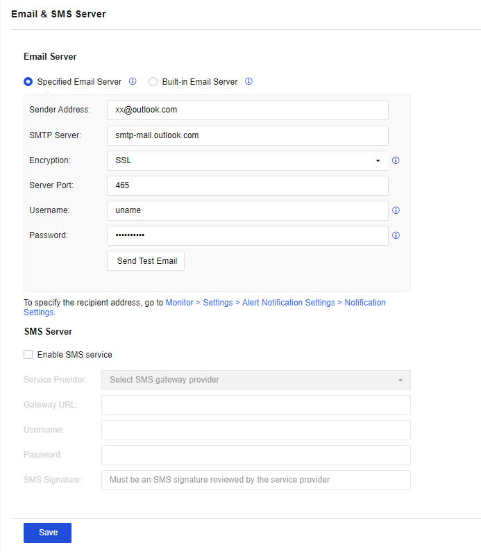
- Click Send Test Email and enter a specified email address that can receive emails to test whether the test email can be received, as shown in the following figure.
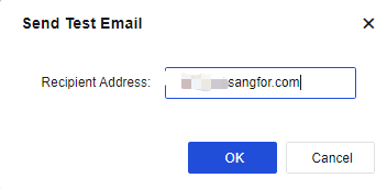
- After the email is sent, the specified email address receives the test email, indicating that the configured Email & SMS Server can send emails normally.
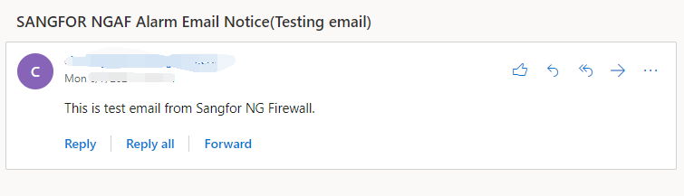
System Time
To specify the system time of a Sangfor device. You can change the time directly on the page or synchronize it with the Time Server.
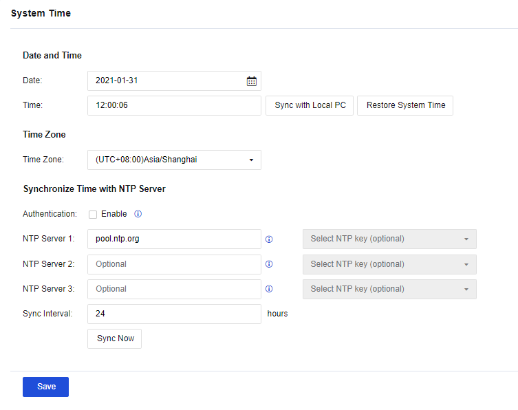
Date and Time: Specify the current system time. You may also manually set the system time in the field. Click Sync with Local PC to make the device’s system time consistent with the PC time on the login console. Click Restore System Time to refresh the device’s system time in real time.
The device’s system time can be set to synchronize with the time server. In the Time Zone section, select the time zone of the device. In the Synchronize Time with NTP Server section, set the address of the time server of the WAN. The device will automatically synchronize with the time of the time server.
NTP Key
You can set NTP keys for synchronization with the NTP server. On the NTP Key page, click Add. The Add NTP Key dialog box appears, as shown in the following figure.
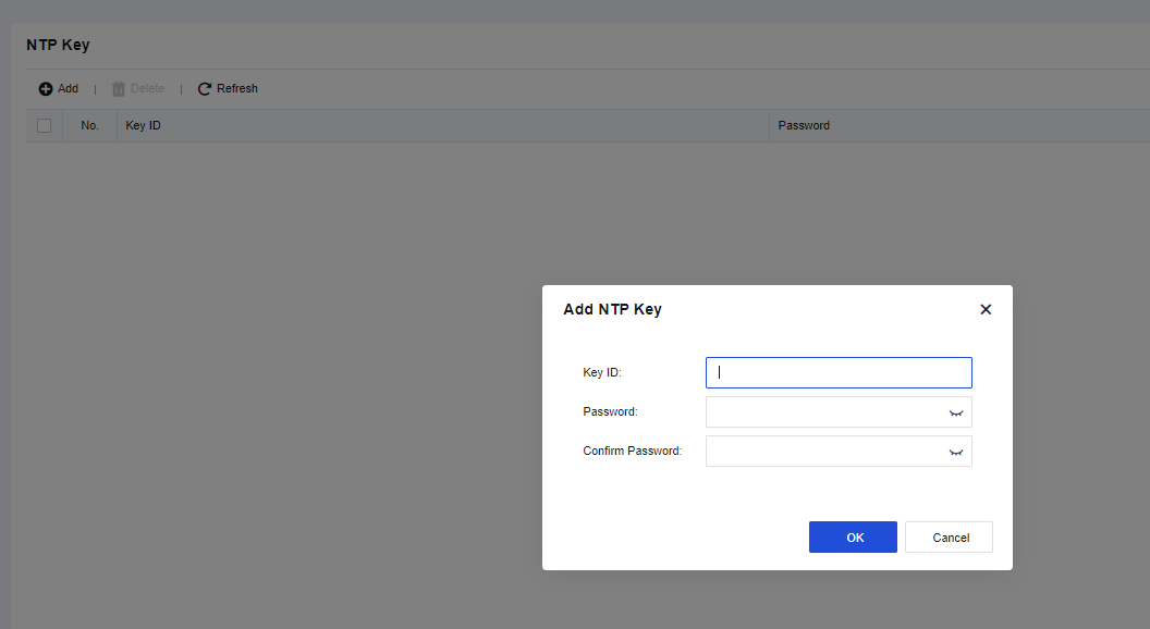
Hosts
To add entries in the Host table of Network Secure. If you need to specify the IP address corresponding to a particular hostname on Network Secure, you can add it on the HOSTS page.
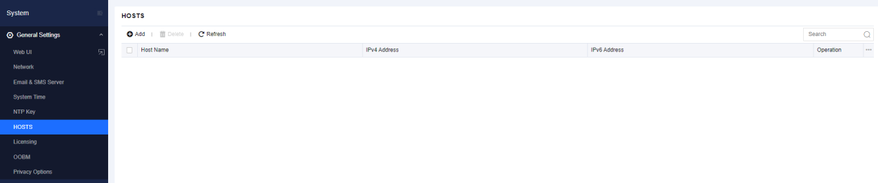
Click Add to add a new entry, as shown in the following figure.
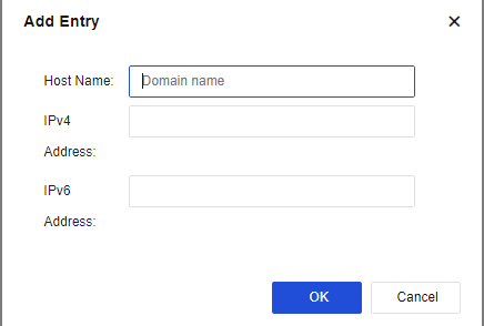
Host Name: Specify the hostname.
IPv4 Address/IPv6 Address: Specify the IP address mapping to the hostname.
Then, click OK to complete the configuration.
Licensing
The Licensing page contains the following sections: Basic Settings, Licensing Network, Security Capabilities and Update, Cloud Service Subscription, and Software Upgrade, as shown in the following figure.
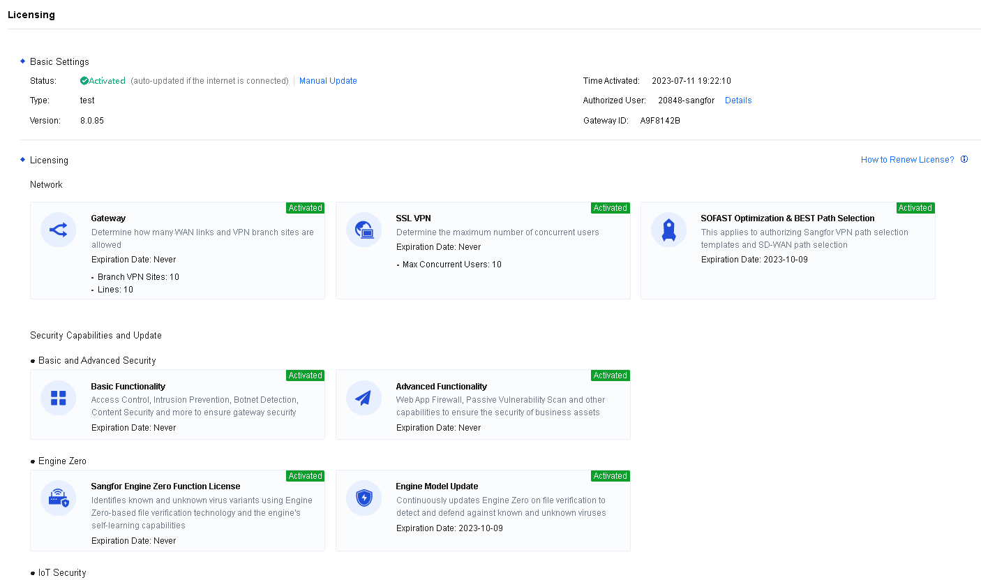
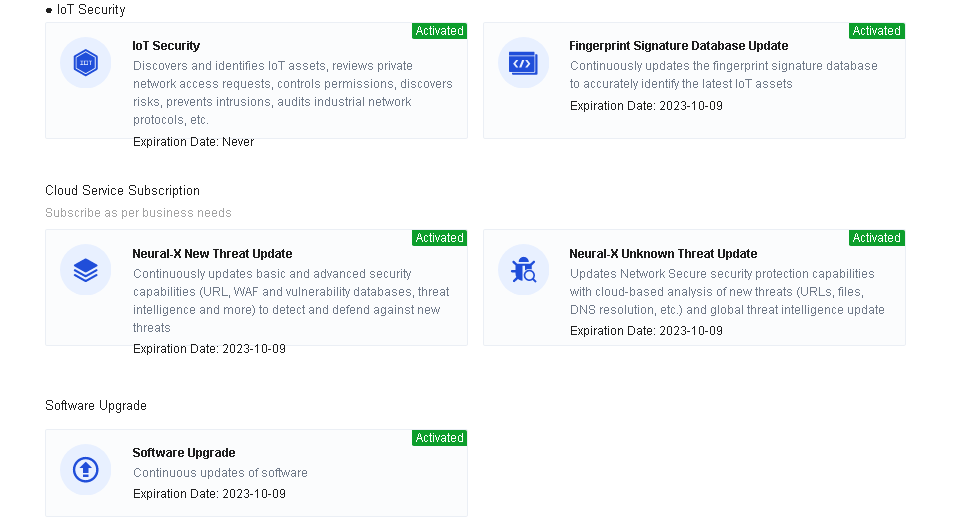
Basic Settings: Specify the Gateway ID, the unique identifier of the Network Secure device software.
Licensing Network: Specify the number of authorized WAN lines, the number of authorized branch VPN sites for accessing standard IPSec VPN lines, the activation of the SSL VPN module, and the number of concurrent users.
Security Capabilities and Update: To enable the device’s basic and advanced security functional modules. Basic Functionality includes access control, intrusion prevention, botnet detection, and content security. Advanced Functionality includes the Web app firewall and passive vulnerability scan. Engine Zero includes the activation of the Sangfor Engine Zero function license and the expiration date of the engine model update.
Cloud Service Subscription: This service is correlated with the cloud to update the security capabilities of Network Secure. This helps the Network Secure detect and defend against new and advanced threats. Neural-X New Threat Update is used to update the rules of all functional modules of Network Secure. Neural-X Unknown Threat Update is to detect and intercept unknown threats effectively. The portal protection subscription service is used to correlate Network Secure with Sangfor Security Assessment to display the detection results of Sangfor Security Assessment on Network Secure. Thus, the comprehensive protection and visualization are improved.
Software Upgrade: This shows the expiration date of Network Secure’s current software upgrade. Before this date, Network Secure can be upgraded to maintain its comprehensive functions.
When the authorization or device is automatically upgraded over the Internet, corresponding functions and authorization update rules can be enabled by manually updating the authorization.
License Activation Method
Offline Activation
- Go to the Licensing page and click Manual Update to go to the Update Licensing page where you can export the hardware information of the device or directly copy it to the clipboard for generating the authorization files. See the figure below.
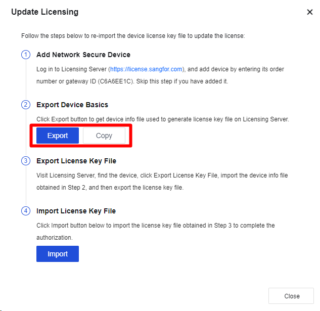
-
Send the device info to the vendor or Sangfor teams.
-
Import the license key file obtained from the vendor or Sangfor teams. Then, the license is activated.
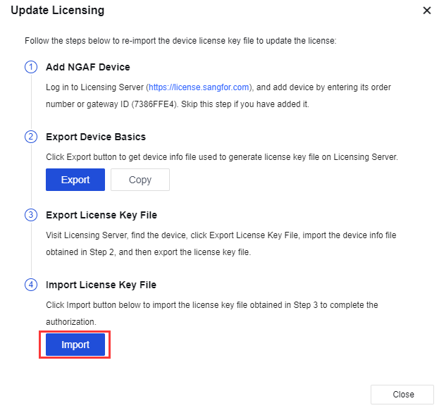
OOBM
Out-of-band management (OOBM) helps isolate the business network from the management network and forward the specified traffic through specified routes. If OOBM is enabled, business traffic and management traffic are independent of each other, and attackers cannot intrude into your management network through the business network. OOBM is enabled by default and generally requires no modifications, as shown in the following figure.
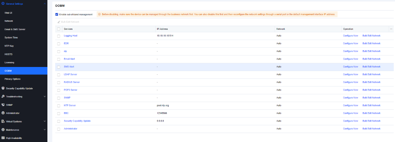
If you want to configure a service, click Configure Now in the Operation column for the service.
If you want to modify the network for a service, click Bulk Edit Network in the Operation column for the service. In the Bulk Edit Network dialog box, select Auto, Management Zone, or Service Zone for Network. Auto is selected by default. If you select Auto, the system selects routes based on their priorities; if you select Management Zone, traffic is forwarded through management interfaces; if you select Service Zone, traffic is forwarded through service zones, as shown in the following figure.
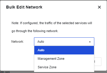
Privacy Options
On the Privacy Options page, you can determine whether to report contents to be improved for the user experience of a product. It helps you continuously improve the product, bringing a better user experience.
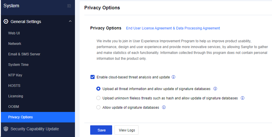
Enable cloud-based threat analysis and update:
If Upload all threat information and allow update of signature database is selected, the device will upload all threat information including the local known threats and unknown threat files(HASH), URL, or DNS. Known threats will enrich the cloud database, and unknown threats will be further analyzed and protected by Neural-X and allow update of local database.
If Upload unknown fileless threats such as hash and allow update of signature databases is selected, allow the device to upload non-file type unknown threats such as HASH, URL, or DNS to the cloud for analysis. Allows updating of the local database.
If Allow update of signature databases is selected, allow update of local signature databases but does not upload unknown threat information.
Click Save. Then, the function takes effect.
Security Capability Update
To update internal databases of the device before the authorization validity period, which cover Unknown Threat Intelligence, Sangfor Engine Zero File Verification Model, URL, Exploit Protection, Application Ident, WAF signature, Anti-Virus, Vulnerability Analysis. The following table describes the rule databases.
| Name | Note |
|---|---|
| Unknown Threat Intelligence | This database will update automatically after five minutes. You are not allowed to click Check for Updates. |
| Sangfor Engine Zero File Verification Model Database | This database can identify the most mainstream active viruses and detect unknown new viruses by analyzing and learning via virus signature identification. |
| URL Database | This database helps the device identify various websites and manage some of the URLs. |
| Exploit Protection Database | This database provides all attack features, including system vulnerabilities and app vulnerabilities to the intrusion prevention template. |
| Application Ident Database | This database provides a set of applications with different app signatures to the application control policy for calling. |
| WAF Signature Database | This database provides a set of Web application attack features to the web application protection template for calling. |
| Vulnerability Analysis Rule | This database analyzes traffic passing Network Secure and finds existing vulnerabilities. |
| Anti-Virus Database | This database is a rule set of botnet and virus files. |
Table 23: Rule Databases
First, check the box in front of the sequence number. Click Enable or Disable to enable or disable the automatic update of internal databases. Click Refresh to view the real-time information of the versions of the internal databases.
Rule Database Update
If the Network Secure device cannot access the Internet, click Offline Update to update the rule database manually within the validity period of the update service.
If the Network Secure device is already networked, click Check for Updates to update the selected rule database within the validity period online.
Intelligence Source
This function is used to configure an intelligence source of the device and an update server to be connected. After the intelligence source is changed, a corresponding threat intelligence database will be downloaded.
Click Database Update Settings to go to the Database Update Settings dialog box. The intelligence sources include an intelligence database in China and a global intelligence database. You can select an update server based on actual WAN lines or select Auto so that the device can automatically detect an accessible update server.
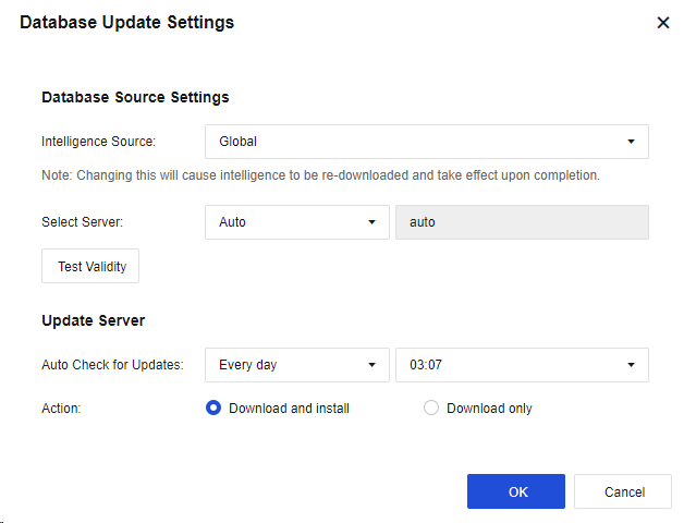
Proxy Settings
When an HTTP proxy server exists in the network, configure it. Then the device is allowed to update the internal database by using the proxy server. When you use the proxy server to configure the update of the internal database, make sure that the device must be in online status.
Click Proxy Settings to enter the Proxy Settings dialog box. Select Enable proxy server. Enter the IP Address and Port of the proxy server. Select Authentication required. Enter the Username and Password to be verified by the proxy server, as shown in the following figure.
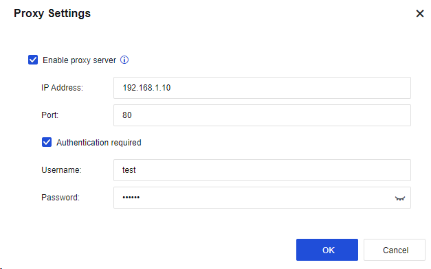
Cloud-Based URL Category Detection
To check the categories of URL databases in the cloud if the categories cannot be searched in the local URL database.
Click Cloud-Based URL Category Detection to go to the Cloud-Based URL Category Detection dialog box. By default, this option is enabled.
Troubleshooting
To troubleshoot and locate network problems. It helps the administrator manage and maintain the device. For more information about the specific operation, see Chapter 10.5 Use of Auxiliary Tools.
Troubleshooting
On the Troubleshooting page, you can search by which module the data packet is rejected when passing through the gateway and why it is rejected, to locate the configuration error quickly or to test whether some rules take effect, including precise traffic analysis, global passthrough and analysis, L2 packet passthrough, and analysis of traffic to Network Secure.
Precise Traffic Analysis
To analyze a source IP address, destination IP address, or domain name, and obtain matching details of traffic to locate the traffic precisely. It is recommended to select this method when some users cannot access the Internet, or some services or applications cannot be used. You must enter the source IP address or destination IP address/domain name for directional analysis to rapidly locate fault causes.
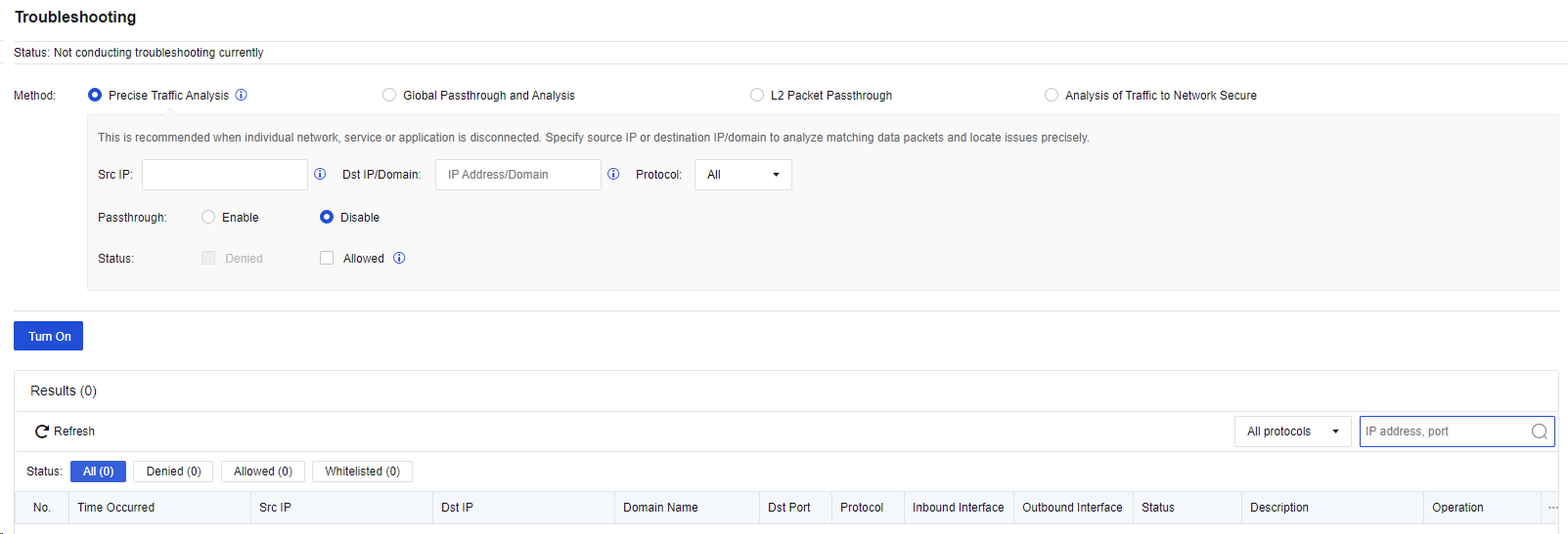
Src IP and Dst IP/Domain: Enter one or both of the source IP address and destination IP address of a packet for precisely matching.
Protocol: Specify the protocol of the packet that can be output to the analysis result list. You can select All, TCP, UDP, ICMP, ICMPv6, and other protocols for this parameter.
Passthrough: Specify whether the policy is allowed for the matched packet.
Status: Specify whether the matched packet is denied or allowed to be output to the analysis result list. You can select Denied for this parameter when troubleshooting the problem that some users cannot access the Internet.
After you click Turn On, the matching details will be displayed in the analysis result list. See the figure below.
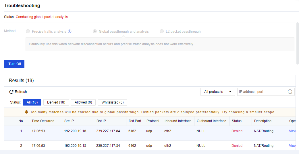
Click Refresh to view the matching situations of the packet in real time. Click View details to view the specific policy matching with this packet. See the figure below.
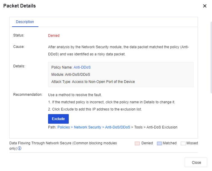
After the troubleshooting is completed, click Turn Off. This makes the address policy specified to the passthrough rule continue to take effect, but not allowed for this packet any longer.
Global Passthrough and Analysis
If you select Global Passthrough and Analysis, all devices’ policies are allowed but not protected any longer. We recommend using this method if large-area networks that cannot be directionally analyzed are interrupted, such as the network environment for device installation.
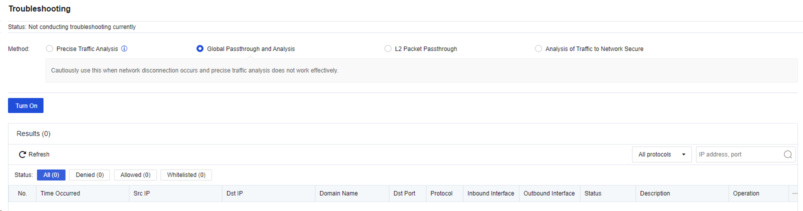
After you click Turn On, the matching details will be displayed in the analysis result list. See the figure below.
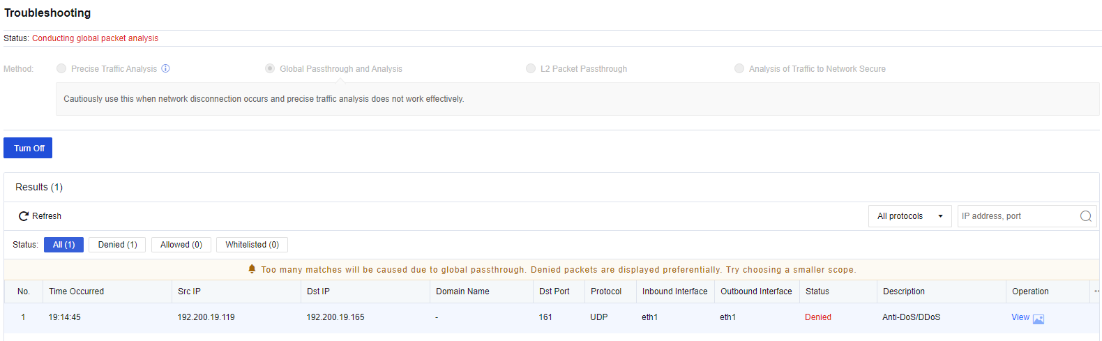
Click Refresh to view the matching situations of the packet in real time. Click View details to view the specific policy matching with this packet. See the figure below.

After the troubleshooting is completed, click Turn Off. This makes the device policy specified continue to take effect, but not allowed for all packets any longer.
L2 Packet Passthrough
To allow the passthrough in the Layer 2 network. Packets will be bypassed on Layer 2. It is recommended to use this method if the fault causes still cannot be located by using the preceding two methods.
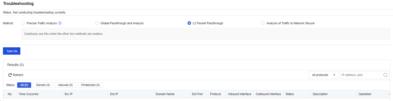
After the troubleshooting, click Turn Off.
Analysis of Traffic to Network Secure
Analysis of Traffic to Network Secure offers a dedicated mode for analyzing inbound traffic to the Network Secure device, which can help you or technical support representatives facilitate the traffic analysis process, as shown in the following figure.
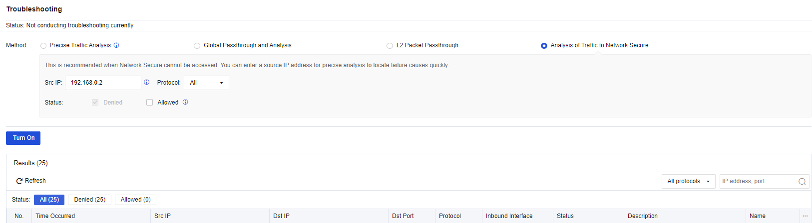
Src IP: Enter the source IP address of the packets sent to the Network Secure device for filtering. You can enter an IP address, an IP address range, or a subnet mask-based network segment.
Protocol: Only packets matching the specified protocol will appear in the analysis result list. You can select All, TCP, UDP, ICMP, ICMPv6, or Other.
Status: When Allowed is selected, allowed packets are also tracked. Usually, the first packet of a single connection is tracked and recorded.
To enable Analysis of Traffic to Network Secure, click Turn On. The details of the inbound packets to the Network Secure device are displayed in the analysis result list, including the ACL policy name. You can click the name to go to the ACL configuration page, as shown in the following figure.
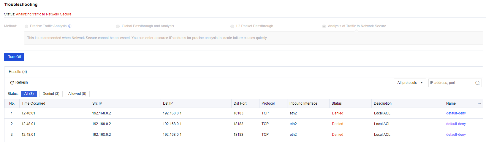
To disable Analysis of Traffic to Network Secure, click Turn Off.
Tools
The analysis tool module includes two tabs: Packet Capture and Technical Support.
Packet Capture
On the Packet Capture tab, you can set a packet capture tool to capture packets passing through the device to locate the problems rapidly. Therefore, this tool can be used as an auxiliary tool for troubleshooting.
For example, when you capture a packet passing through the WAN port 80 accessed by the LAN endpoint 192.168.1.10, perform the following steps:
- Click Create Capture Task, select Rolling. In the Settings dialog box, select a LAN interface (eth2) for the Interface parameter, set the IP Address parameter to 192.168.1.10, and set the Port parameter to 80, as shown in the following figure.
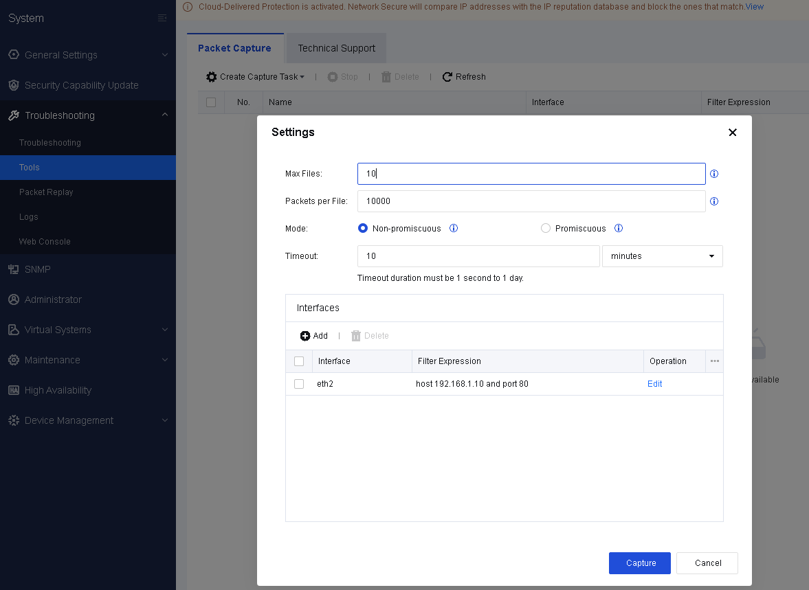
- Click Capture. Then, the capture program starts to execute, as shown in the following figure.
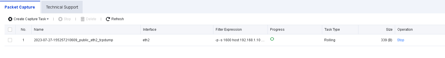
-
Make an HTTP request on the endpoint 192.168.1.10. For example, open the webpage http://www.gov.cn.
-
Click Stop and then click Download to download the packet to your PC. See the figure below.
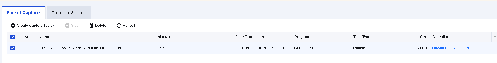
- Use Sniffer, Ethereal, Wireshark, or other packet capture software to view specific information of a packet file. The analysis result shows that the endpoint accessed the website http://www.gov.cn, as shown in the following figure.
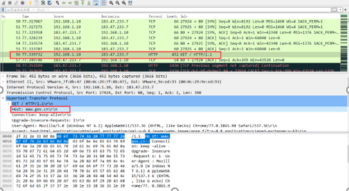
Technical Support
On the Technical Support tab, you can configure a technical support tool that allows the technical support personnel to troubleshoot and check the system’s health, and helps them maintain devices with ease.
Blackbox: Obtain BlackBox information, which allows you to download the information. In this way, the technical support personnel can troubleshoot with ease.
Reset Database: Reset a database. If you reset the database, all data in the built-in data center will be cleared. Proceed with caution.
Packet Replay
Packet replay is a built-in tool of Network Secure, which can efficiently replay the previously captured network attacks for network forensics and verification.
Logs
On the Logs page, you can view the operating status logs of all modules on the device. You can determine whether the modules are working properly based on the logs, as shown in the following figure.
Click Options. The Settings dialog box appears. Select the type of logs you want to view, as shown in the following figure.
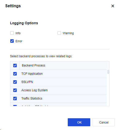
Click OK. Then, all the selected log information is displayed.
Web Console
Web Console allows you to configure and view device settings using command lines on a web page. After you select the Web UI management method for the admin on the System > Administrator page, you can use Web Console in the same way as using a CLI via SSH. For more information about the command lines, refer to the command-line manual.

SNMP
To manage and view the relevant information (such as the interface status, interface traffic, and route) of Sangfor devices in SNMP mode with other network management devices or software. It helps users easily manage, maintain, and monitor the network. The interface is shown below.
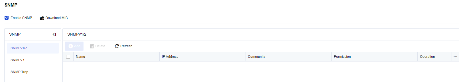
If you select Enable SNMP, other devices and management software can read the device information through SNMP.
Download MIB: This allows you to download MIB databases supported by the NSF device. You can import the SNMP client for use.
SNMPv1/2 allows other devices to connect the device through the SNMP v1/v2 protocol and defines connection parameters. Click Add and configure the parameters in the Add SNMPv1/2 dialog box.
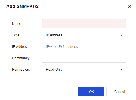
Name: Specify the name of the management host.
Type: Specify the type of the management host. You can select IP address or Subnet from the drop-down list. If you select IP, the SNMP management host is set as a IP. If you select Subnet, the SNMP management host is set as a subnet. All hosts in the subnet can manage the device through SNMP.
IP Address: Specify the IP address or address range of the SNMP management host. If you select IP for the Type parameter, this parameter specifies the IP address of the SNMP management host. If you select Subnet for the Type parameter, this parameter specifies the subnet address and its mask of the SNMP management subnet. An IPv6 address is supported.
Community: Specify the community name for the SNMP management host that accesses the device.
Click OK. Then, the configuration is saved.
SNMPv3 allows you to configure some advanced expansion options necessary for communication in SNMPv3.
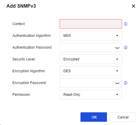
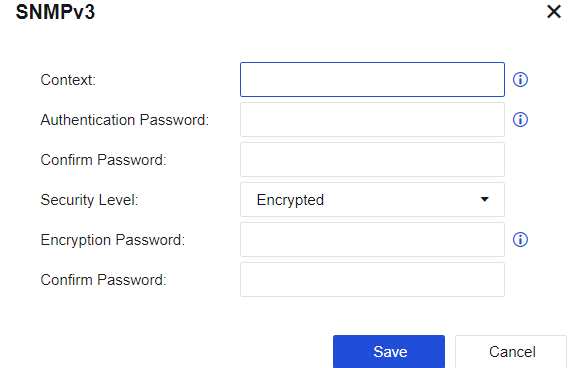
Context: Specify the name of the user.
Authentication Password: Specify the password used for authenticating SNMPv3 users. The authentication password contains more than 8 characters and cannot contain spaces. It is encrypted with the MD5 algorithm.
Encryption Password: Specify the password for message encryption. The encryption password contains more than 8 characters and cannot contain spaces. It is encrypted with the DES algorithm.
Security Level: Specify whether to encrypt SNMP authentication and management information. You can select Encrypted or Not Encrypted from the drop-down list. If you select Encrypted, the system applies the encryption and authentication simultaneously by first encrypting the data and then conducting the message digest calculation with the authentication technology. If you select Not Encrypted, only the authentication technology is applied.
Click OK. Then, the configuration is saved.
SNMP Trap: Actively send an SNMP message to the administrator to monitor the status of Network Secure in real time.
Click Add and configure the parameters in the Add SNMP Trap dialog box.
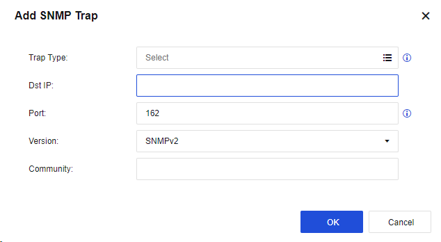
Trap Type: Specify the type of messages actively sent by Network Secure, including Temperature Alert, CPU Alert, Link Failure Alert, Warm Start Alert, etc. The OID corresponding to each message type can be viewed by clicking SNMP OID.
Dst IP: Specify the destination host IP address for sending SNMP Trap messages, namely the IP address of the SNMP client. Both IPv4 and IPv6 addresses are supported.
Port: Specify the port number used by the target host for listening.
Version: You can select SNMPv1, SNMPv2, or SNMPv3 from the drop-down list.
Community: Specify the name of the community sending SNMP Trap messages.
If you select SNMPv3 for the Version parameter, the Community parameter is unavailable. You must set the following parameters:
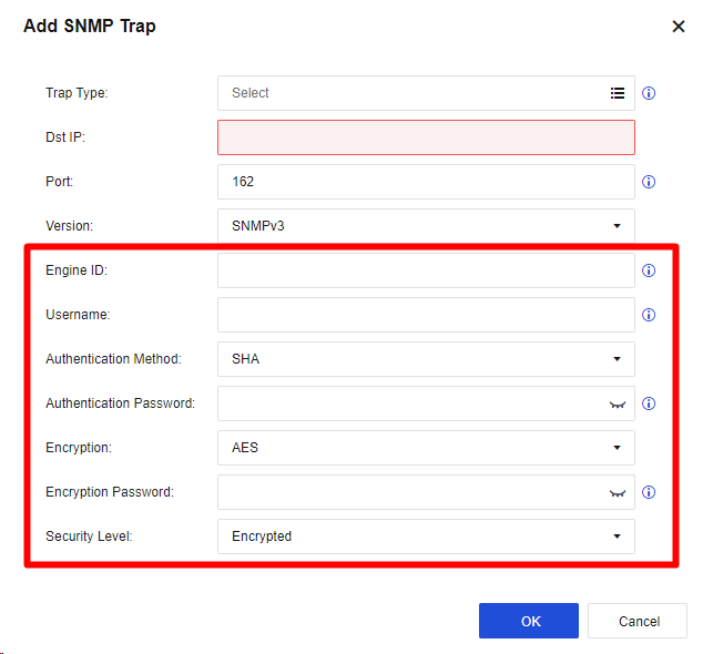
Engine ID: Specify the Engine ID of the target host (snmpEngineID), in hexadecimal string form, excluding prefix 0x.
Username: Specify the name of the SNMPv3 user existing on the SNMP client.
Authentication Method: Specify the authentication method of the SNMPv3 user. You can select MD5 or SHA from the drop-down list. By default, SHA is selected.
Authentication Password: Specify the authentication password of the SNMPv3 user.
Security Level: Specify the security level of SNMPv3 Trap messages. You can select Encrypted or Not Encrypted from the drop-down list. If you select Encrypted, specify the Encryption and Encryption Password parameters.
Encryption: Specify the encryption method of the SNMPv3 Trap message. You can select DES and AES from the drop-down list. By default, AES is selected.
Encryption Password: Specify the encryption password of SNMPv3 Trap messages.
Administrator
To manage login usernames and admin roles in the web console. By default, the account and password of the admin account are admin and "admin". Navigate to System > Administrator. On the Administrator page, you can add, edit, delete, enable, and disable the admin account.
You can also specify the logged-in users who can manage the device through the console.
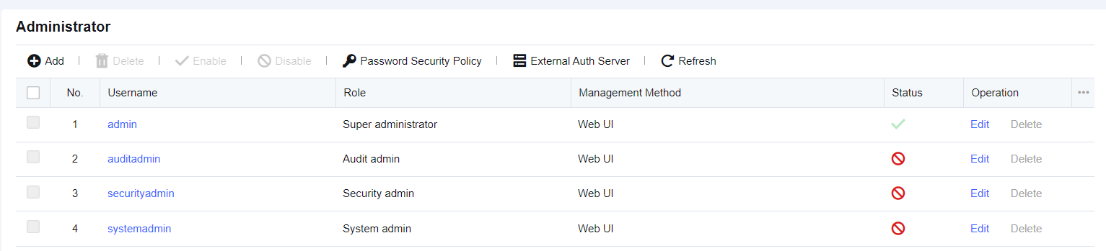
By default, four admin roles are available, including Ordinary Admin, Security Admin, Audit Admin, and System Admin.
Click Add. Then, the Add Administrator dialog box appears. See the figure below.
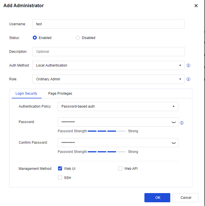
Username: Specify the name of the admin account.
Status: Specify whether the admin account is enabled or disabled.
Description: Specify the description of the account.
Auth Method: Support Local Authentication, Remote Authentication, and Remote/Local Authentication. Remote Authentication is not selected for created accounts. When Remote/Local Authentication is selected, local authentication is used when the external authentication server cannot be accessed.
Role: Specify the role of the admin account. You can select one of the five roles from the drop-down list, in which the system administrator, audit administrator, and security administrator are three separate accounts.
-
Ordinary admin: Indicates an ordinary admin account that is granted permissions to manage all modules.
-
System admin: Responsible for the management and maintenance of daily running environments of software. This account is granted permission to configure basic network environments and other management permissions irrelevant to security policies.
-
Security admin: Has the permissions to view and modify modules related to security policies.
-
Audit admin: Only has the permission to view the built-in data center.
-
Remote authentication user: You can select a user account on the external server as an admin account.
Login Security: Specify the authentication policy and management method of the admin account.
Authentication Policy: Specify the authentication policy of the admin account. Currently only Password-based auth are available.
Management Method: Specify the method for managing the device by the admin account. You can select one of the following four management methods:
Web UI: This allows you to log in to the management device using the admin account via web UI or webpage.
Web API: Allows the third-party platform to log in to the management device by performing web API operations.
SSH: Allow you to log in and manage devices via SSH.
Page Privileges: Specify whether the account has permission to view or edit modules in the console or data center.
Click Password Security Policy to set the security policy by which the console manages the admin password. You can set whether the password must be changed for the next-time login and the maximum number of days during which the password is available. Note: Only the admin account is granted this permission.
Note:
Only the admin account is granted this permission.
Click External Auth Server to authenticate the admin account of the external server. You can select TACACS or RADIUS for the Authentication Method parameter. See the figure below.
Maintenance
System maintenance refers to the modification of the system to be adapted to various system environment changes and other factors and to ensure that the system can work as expected. The Maintenance function includes the following modules: Backup/Restore, Upgrade, Past Updates, Restart, and Service Packs.
Backup/Restore
To download the device configuration to save it to the local PC or recover the device configuration files that have been backed up.
Back Up Configuration: Used to download and back up the existing configuration on the device. Click Download to back up the current configuration.
Restore Configuration: Restore configuration files that have been backed up. There are two methods to restore a configuration file:
Method 1: Restore from auto backup file. If you select this method, the device automatically backs up the configuration once in the early hours of the morning daily. By default, it saves the configuration file for a week. To restore a configuration file backed up, select the file, and click Restore.
Method 2: Restore from backup on local PC. If you select this method, click the list icon to browse and open the backup file. Click Restore to restore the configuration backup copy.
Restore to Factory Defaults: Click Restore to Factory Defaults to restore the device to factory settings.
Notice:
The device will be restarted if you select Restore Configuration or Restore to Factory Defaults. Make sure the device can be disconnected from the Internet before restoring. We recommend restoring the configuration when no services are running or in the low-peak period of services, avoiding impacts on normal services.
Upgrade
Upload an upgrade package on the device interface to upgrade the system version. After a new version is released, if you determine that the system meets the conditions required for an upgrade and requires a version upgrade, click Update to Another Version. The Upgrade page appears. Click Upload Package to upload the local upgrade package to upgrade the system. See the figure below.
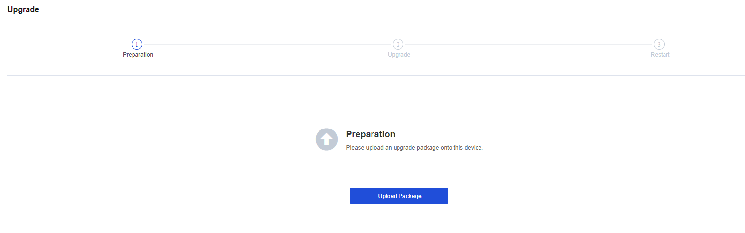
For more detailed steps, see Chapter 11 Product Upgrade Guide.
To view upgrade records, click View Upgrade History. See the figure below.
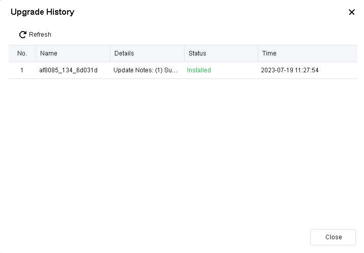
To roll back to the previous version before the upgrade, click Rollback. This high-risk operation will restart the device and restore the configurations to their pre-upgrade state. Perform this operation only when the issues for the upgraded version cannot be resolved.
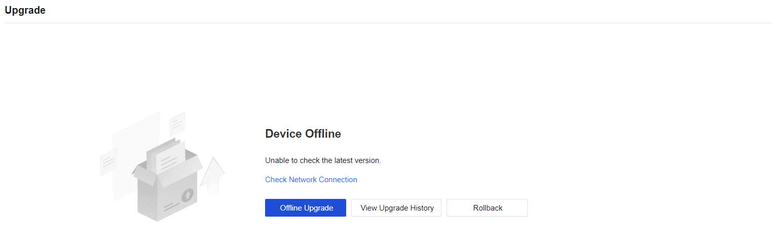
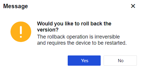
Past Updates
To show functions that are added and deleted in the current version and their advantages. See the figure below.
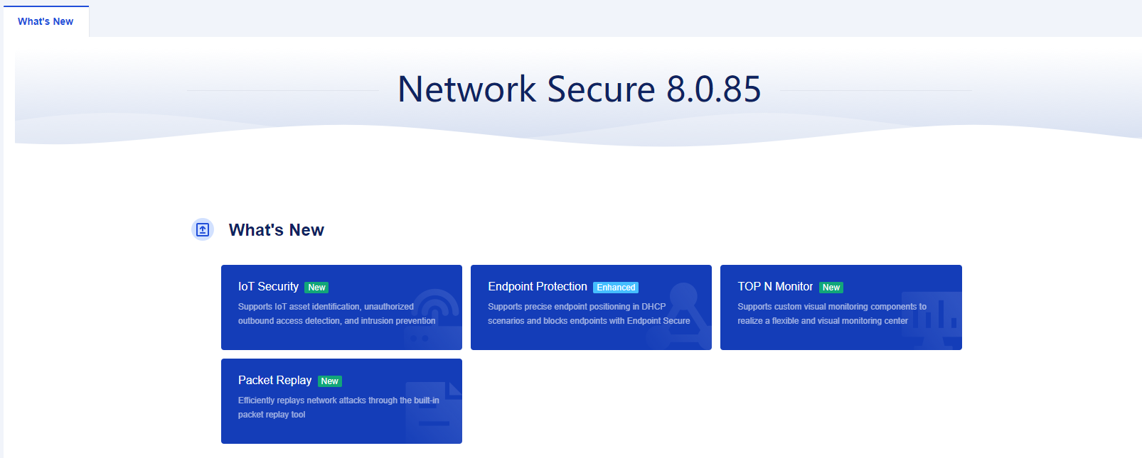
To view the update details, click on the module name and it will redirect to the details part. See the figure below.
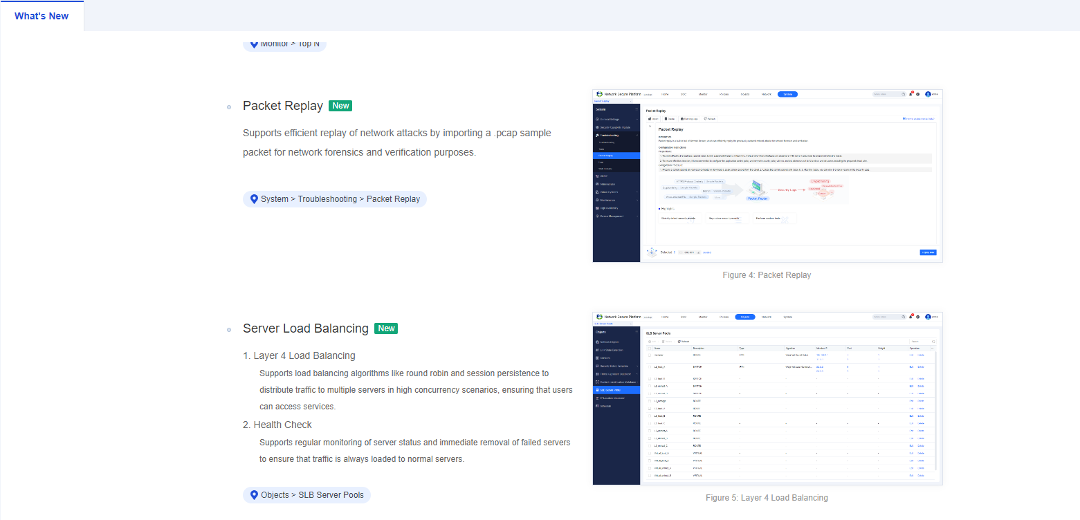
Restart
The Restart module includes three function buttons, including Restart Device, Restart All Services, and Stop SSL VPN Service. If you click the Restart Device or Restart All Services button, the device will be disconnected from the Internet and services will be affected. Proceed with caution.
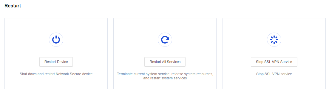
Service Packs
To obtain a patch package that is used to upgrade the system version. For more information about the detailed configuration, please refer to Chapter 10.4 Patch Update Guidance.
High Availability
Overview
High availability is an effective solution for mitigating the risk of a single point of failure and ensuring business continuity. It reduces the potential for network service interruptions and is suitable for scenarios where high network reliability and uninterrupted business continuity are required.
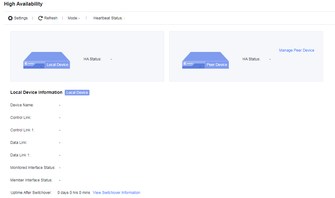
Note:
Both devices’ model, number of interfaces, and the OOBM must be consistent before configuring the High Availability. If the device model or the number of interfaces differs but needs to build High Availability, please contact our support representative to evaluate if the hardware specification meets the requirement.
HA Policy Settings
Click Settings, and the HA Policy Settings page will appear.
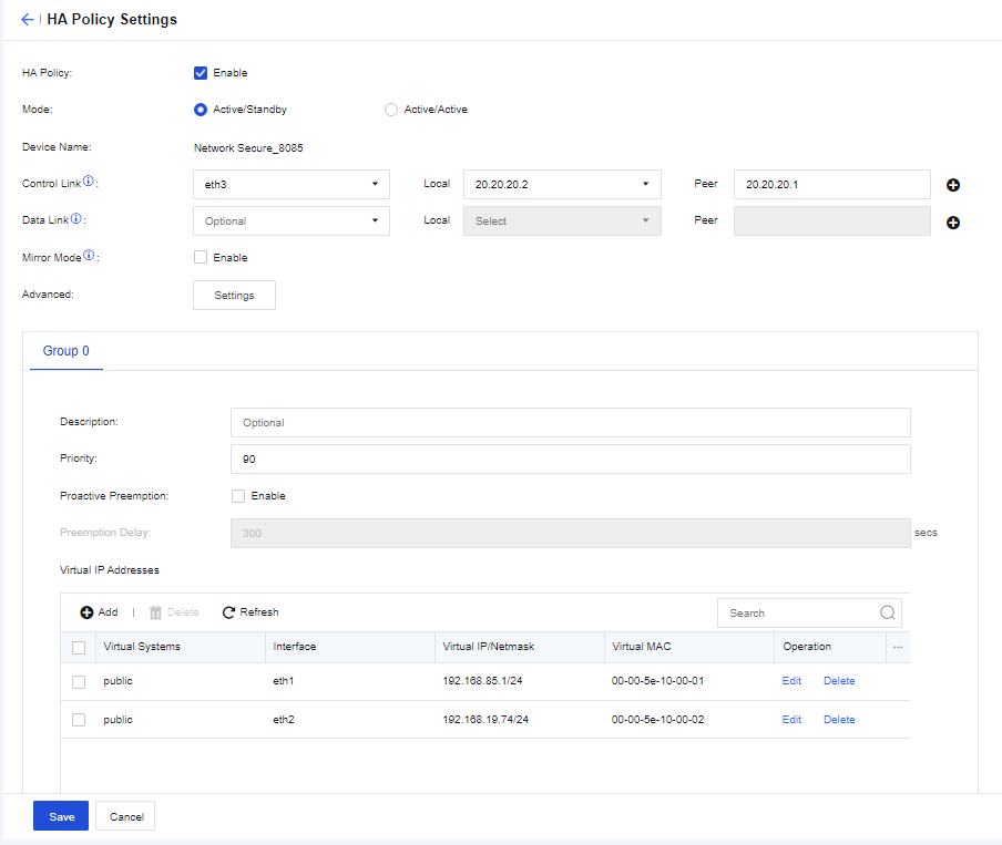
HA Policy: When Enable is selected, you can configure HA policy settings.
Mode: Specify the HA mode. You can select Active/Standby or Active/Active.
Control Link: Responsible for transmitting HA heartbeat packets, which include local HA settings, local HA status, and other information. After you configure the control link using the same interface for the local and peer devices, the control link determines the active and standby devices and synchronizes settings from the active device to the standby device to establish an HA mode. You can use an aggregate interface for the control link and ensure that the interfaces of the active and standby devices are the same.
Data Link (Optional): Responsible for synchronizing data, such as sessions. When no data link is set or when the data link fails, the control link takes the place of the data link. When the control link fails, the data link transmits heartbeat packets.
Advanced: Click Settings to customize advanced settings, as shown in the following figure.
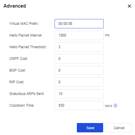
Priority: Specify the priorities of the interfaces selected in the interface list. Higher values indicate higher priorities. Enable Proactive Preemption after setting the priority because priority settings must work with this function. Assume that two devices are in active/standby mode (one device is active whereas the other is inactive as a standby), and you assign a priority of 90 to Device A (preemption enabled) and a priority of 80 to Device B (preemption enabled or disabled). When Device A fails, Device B becomes active. When Device A recovers, Device A replaces Device B as the active device, and Device B becomes standby.
Proactive Preemption: Specify whether to allow the failed active device to become the active device again after it recovers. This function must work with the Priority settings.
Preemption Delay: Specify the preemption delay, which is set to 300 seconds by default.
Virtual IP Addresses: Specify virtual IP addresses for service interfaces to enable communication. The virtual IP addresses are synchronized from the active device to the standby device and are only assigned by the active device. During a failover, the new active device assigns the virtual IP addresses while the new standby device removes them. To add a virtual IP address, click Add, as shown in the following figure.
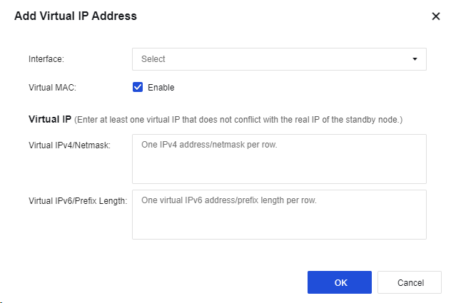
Monitored Object Management: Specify the interfaces and links to be monitored. To set objects to be monitored, click Manage, as shown in the following figure.
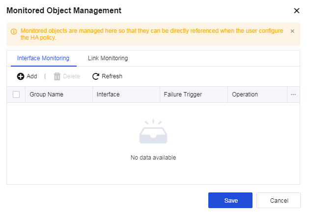
Interface Monitoring: Specify the interfaces to be monitored. You can add multiple interface groups and assign multiple interfaces to each group. For each interface group, you can select All fail or One fails as the Failure Trigger for failover. To add a group, click Add under the Interface Monitoring tab, as shown in the following figure.
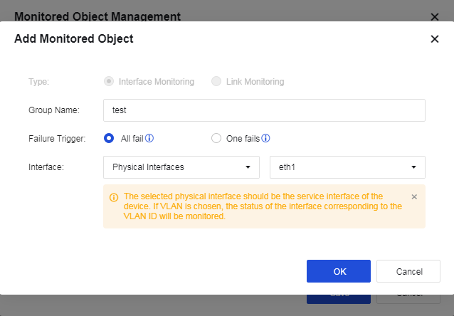
Link Monitoring: This setting takes effect when the link state detection on the Objects > Link State Detection page is referenced. The interfaces selected here are checked for possible issues with them or their links. If you do not select Link Monitoring, the system only checks the status of the interfaces specified in Interface Monitoring. A failover is not triggered until the physical interface is down. You can add multiple link groups and assign multiple links to each group. For each link group, you can select All fail or One fails as the Failure Trigger for failover. To add a group, click Add under the Link Monitoring tab, as shown in the following figure.
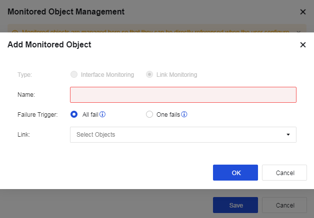
Monitored Object: Display the monitoring groups specified in Monitored Object Management. Failovers are triggered based on the specified conditions.
Sync Options
Sync Options defines how HA settings are synchronized. It includes two roles, Active controller and Passive controller, and provides two synchronization methods, namely Auto Sync and Sync Now, as shown in the following figure.
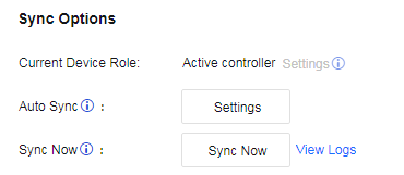
Objects: Used to select objects to sync between the two devices, which include the session list. The device checks settings for changes every 10 seconds.
Current Device Role: Specify the device’s role in synchronization, which includes Active controller and Passive controller.
Active/Standby: The active device is always the active controller, whereas the standby device is always the passive controller. You cannot switch the roles of the two devices manually.
Active/Standby Mirror Mode: The active device is always the active controller, whereas the standby device is always the passive controller. You cannot switch the roles of the two devices manually.
Active/Active: The device whose Group 0 is set to active is the active controller, whereas the device whose Group 0 is set to standby is the passive controller. You cannot switch the roles of the two devices manually.
Active/Active Layer 2 Mode: You can switch the roles of the two devices manually.
Notice:
- Settings of the active controller can be synchronized to the passive controller, and the passive controller cannot modify the synchronized settings.
- In the active/standby or active/active mode, the device’s role depends on the status of Group 0. In the active/active Layer 2 mode, you need to assign a role to the device manually.
- Manual role switching is only supported in the active/active Layer 2 mode.
HA Traffic
If you use Network Secure devices in the active/active or active/active Layer 2 mode, and the upstream and downstream devices of the Network Secure devices are routers, you need to enable HA Traffic to avoid traffic inconsistency. Otherwise, do not enable this option. When enabled, Network Secure determines, based on the hash algorithm, whether to send the packet received from the service interface to the peer device through the synchronization interface for a security check. This ensures that all packets from the same flow undergo security checks on the same device, avoiding network unavailability and ineffectiveness of security checks due to asymmetric routing. After the security check, the peer device sends the packet back through the synchronization interface so the local device can forward the packet. This prevents network unavailability caused by dropped packets in the downstream device’s routing interface due to mismatched destination MAC addresses. The configurations are shown in the following figure.
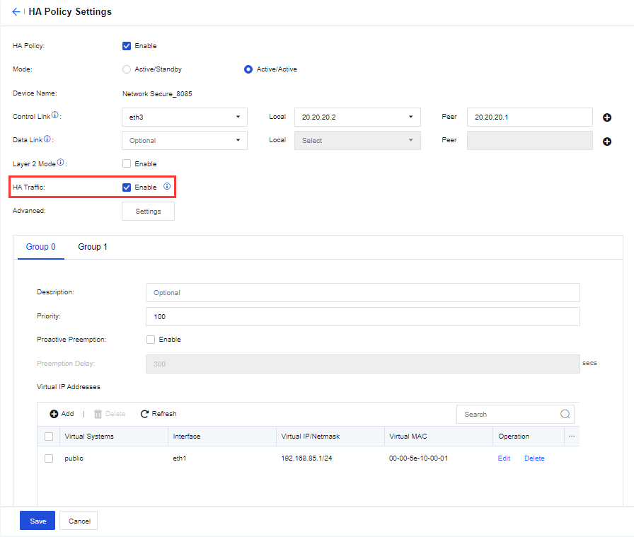
The workflow is as follows:
-
When a PC accesses the server, the packet goes through Network Secure 1. Network Secure 1 determines, based on the hash algorithm, whether the security check should be performed. After the check is completed, Network Secure 1 forwards the packet to the server.
-
The packet returned by the server arrives at Network Secure 0.
-
Network Secure 0 determines, based on the hash algorithm, whether Network Secure 1 should perform the security check (calculation results for packets with the same IP address are the same). Network Secure 0 sends the packet to Network Secure 1 through the HA aggregation link.
-
After receiving and checking the packet, Network Secure 1 sends the packet back to Network Secure 0 through the HA aggregation link.
-
Network Secure 0 sends the returned packet to the PC.
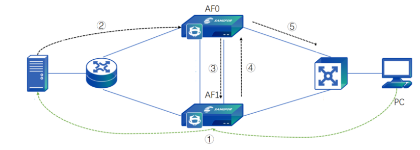
Link Aggregation
If you use Network Secure devices in the active/active Layer 2 mode, and the upstream and downstream devices of the Network Secure devices are routers that adopt link aggregation, you need to enable Link Aggregation to avoid transmitting the request packet and the return packet using different paths. For example, if a request packet passes through Firewall A while the return packet passes through Firewall B, the return packet will be dropped due to inconsistent paths. Link aggregation ensures that the request packet and the return packet are forwarded by the same Network Secure device. When enabled, the backend program automatically generates a number of 0 or 1 that does not appear on the page for each Network Secure device. The Network Secure device calculates results for all packets passing through the LAN or WAN interface based on their source and destination IP addresses. Packets are sent to and then forwarded from the corresponding Network Secure devices according to their calculation results (for example, a packet with a calculation result of 0 will be sent to and then forwarded from the Network Secure device marked as No.0). The configurations are shown in the following figure.
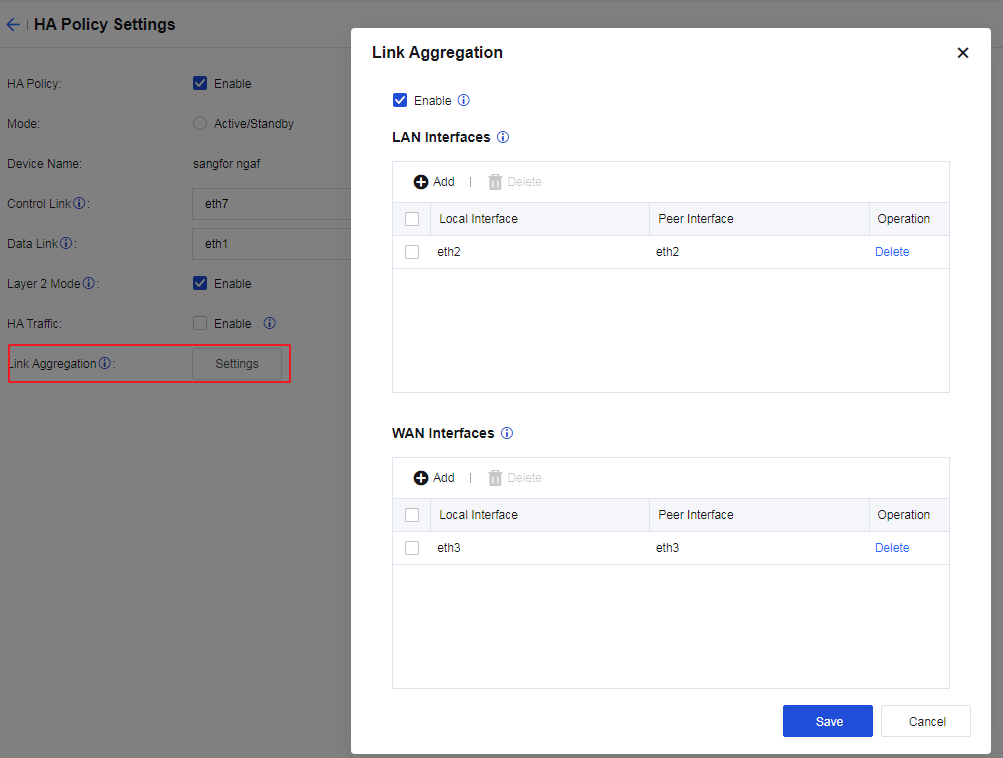
Enable: Check Enable to enable link aggregation. Conditions for enabling link aggregation: HA policy is enabled; the active/active Layer 2 is used; interfaces for data synchronization are set; and at least two Layer 2 interfaces are available.
LAN Interfaces: Specify the downstream LAN interfaces for the local and peer devices.
WAN Interfaces: Specify the upstream WAN interfaces for the local and peer devices.
The workflow is as follows:
-
When a PC accesses the server, the packet goes through Network Secure 1. Network Secure 1 determines, based on the hash algorithm, whether the security check should be performed. After the check is completed, Network Secure 1 forwards the packet to the server.
-
The packet returned by the server arrives at Network Secure 0.
-
Network Secure 0 determines, based on the hash algorithm, whether Network Secure 1 should perform the security check (calculation results for packets with the same IP address are the same). Network Secure 0 sends the packet to Network Secure 1 through the HA aggregation link.
-
After receiving and checking the packet, Network Secure 1 sends the packet back to Network Secure 0 through the HA aggregation link.
-
Network Secure 0 sends the returned packet to the PC.
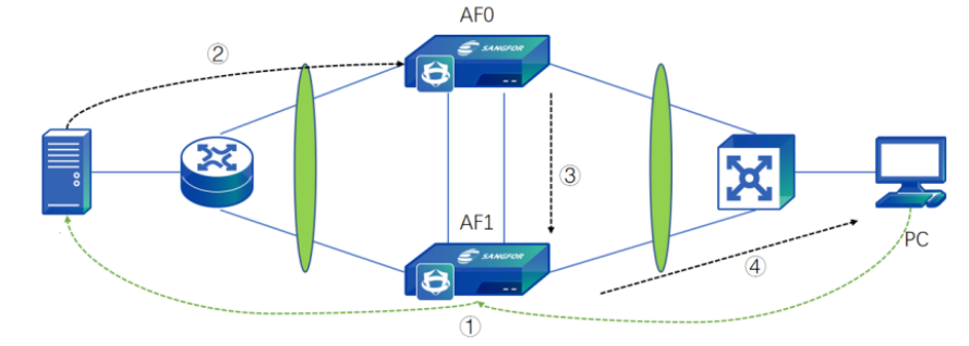
Notice:
- The monitoring interfaces of the active and standby devices must be the same.
- If the priorities of the virtual groups are the same, no preemption will occur regardless of whether preemption is enabled.
- Settings are synchronized in the following two ways: bulk synchronization and incremental synchronization. When the active controller sends a request to the passive controller for synchronizing settings from the peer device to the local device, bulk synchronization is triggered. After the bulk synchronization is completed, the device checks settings for changes every 10 seconds. If changes are detected, an incremental synchronization is triggered for synchronizing the modified settings of the active controller to the passive controller. A passive controller does not have permission to modify settings. To manually modify the standby device’s settings, change the device’s synchronization role. Otherwise, changes cannot be submitted.
- If the database version of Device A is valid while that of Device B is expired, synchronizing Device A’s upgraded database to Device B will fail. However, this does not affect the synchronization of other settings.
- The two HA devices must be the same model. Devices of different models have a different number of interfaces. This can cause the two HA devices to work improperly because interface settings are also synchronized during the synchronization of settings between the two devices.
HA Modes
Overview
Active/Standby Mode
In the active/standby mode, only the active device handles the business traffic. The active device assigns the virtual IP addresses for managing business traffic, while the standby device does not. When the active device fails, a failover is triggered. The new active device assigns the virtual IP addresses while the new standby device removes them to implement automatic failover.
In the active/standby mode, the active device works as the active controller to synchronize its settings to the standby device, and the standby device cannot modify the synchronized settings.
Active/Standby Mirror Mode
In active/standby mode, only the information of interfaces assigned virtual IP addresses is synchronized with the standby device. Their IP and MAC addresses are not synchronized for interfaces not assigned virtual IP addresses. However, in the active/standby mirror mode, Network Secure uses physical IP addresses instead of virtual ones. The information of all interfaces except for the out-of-band management, control link, and data link interfaces are synchronized to the standby device. The two devices mirror each other and even have identical MAC addresses.
Active/Active Route Mode
The active/active route mode applies to scenarios where a single device experiences a heavy workload due to excessive business traffic. In the active/active routing mode, both devices are active and prepared to act as standby for each other to ensure load balancing. The traffic is divided into two parts, each handled by the corresponding device. For the local device, the peer device acts as its standby. A failover is triggered when the local device fails, and the peer device handles the business traffic sent to the local device.
Here is an example. The business traffic is divided into Traffic A and Traffic B, which are handled respectively by Network Secure 1 and Network Secure 2. For Traffic A, the virtual IP address is set in Group 0, where Network Secure 1 is the active device, and Network Secure 2 is the standby device. When Network Secure 1 fails, Network Secure 2 becomes the new active device for handling Traffic A, whereas Network Secure 1 becomes the standby device. For Traffic B, the virtual IP address is set in Group 1, where Network Secure 2 is the active device, and Network Secure 1 is the standby device. When Network Secure 2 fails, Network Secure 1 becomes the new active device for handling Traffic B, whereas Network Secure 2 becomes the standby device.
Active/Active Layer 2 Mode
In the active/active Layer 2 mode, the two devices are deployed in the Layer 2 mode or the Layer 2 virtual wire mode. Both devices are active without the concepts of Group 0 and Group 1.
In this mode, if the upstream and downstream devices use aggregate interfaces, and the request and response packets are transmitted using different paths (asymmetric routing), you need to enable link aggregation to ensure normal traffic forwarding. When a packet passes through one of the Network Secure devices after link aggregation is enabled, the Network Secure device determines which Network Secure device should handle the packet by calculating the packet’s hash value. If the hash values of a flow’s request and response packets are identical, they are handled by the same Network Secure device. For packets that the peer Network Secure device should handle, the local Network Secure device sends them to the peer device through the data link.
Active/Standby Deployment Case
In the active/standby deployment, one device is active while the other is a hot standby. The two devices employ the heartbeat interface to detect each other’s existence and synchronize settings and sessions. When the failure of the active device triggers a failover, business traffic is automatically directed to the standby device. Mechanisms such as session synchronization ensure the continuity and stability of the business traffic. The active/standby deployment supports the routing mode and the bridge mode (which includes the Layer 2 mode and the virtual wire mode).
Configuration Case
An enterprise plans to deploy two Network Secure devices to its VRRP-based LAN in the active/standby mode. The network topology is shown in the following figure.
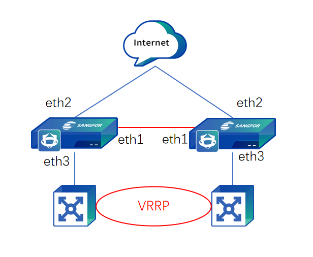
Prerequisites
-
Conditions for an HA deployment: The two devices must have the same software version, memory, interfaces, and licenses.
-
Prepare the service interfaces (LAN and WAN), heartbeat interface, data synchronization interface, and IP addresses for the two devices in advance.
-
Enable the Layer 2 mode and configure related security policies for the active device.
-
Configure the standby device after configuring the active device.
Configuration Procedures
-
Configure the heartbeat interface for the active device. Go to Network > Interfaces > Physical Interfaces to configure an IP address for the eth1 interface. In this case, the IP address is set to 11.1.1.1/24, as shown in the following figure.
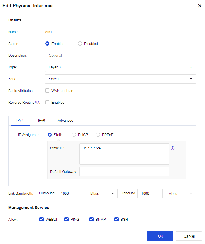
- Enable the HA policy and select the Active/Standby mode for the active device. Go to System > High Availability and click Settings. On the HA Policy Settings page, check Enable for HA Policy, select Active/Standby as the Mode, select eth1 as the Control Link interface, and set the peer device’s IP address to 11.1.1.2 (the data link is optional in the active/standby mode).
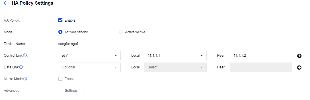
- Set the priority and virtual IP addresses for the active device. Set Priority to 100. On the Group 0 tab, click Add in the Virtual IP Addresses section. Select eth2 for Interface, and enter 10.2.1.3/24 in Virtual IPv4/Netmask. Then select eth3 for Interface, and enter 10.3.1.3/24 in Virtual IPv4/Netmask, as shown in the following figure.
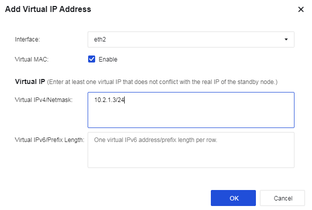
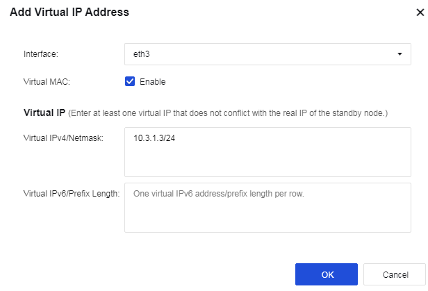
- Configure interface monitoring for the active device. In the Monitored Object Management dialog box, select the Interface Monitoring tab and click Add. Select One fails for Failure Trigger, select Physical Interfaces for Interface, and select eth2 and eth3 as the service interfaces to monitor.
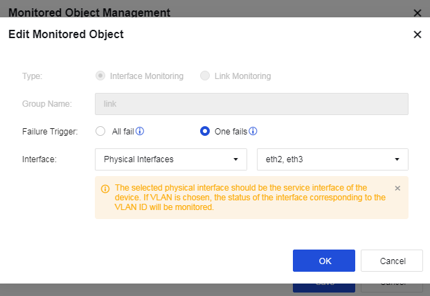
- Associate the monitored object with the active device. Select the link configured in the preceding step for Monitored Object, as shown in the following figure.
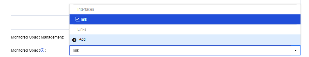
-
Click Save button to save the configuration.
-
Configure the heartbeat interface for the standby device. Go to Network > Interfaces > Physical Interfaces to configure an IP address for the eth1 interface. In this case, the IP address is set to 11.1.1.2/24, as shown in the following figure.
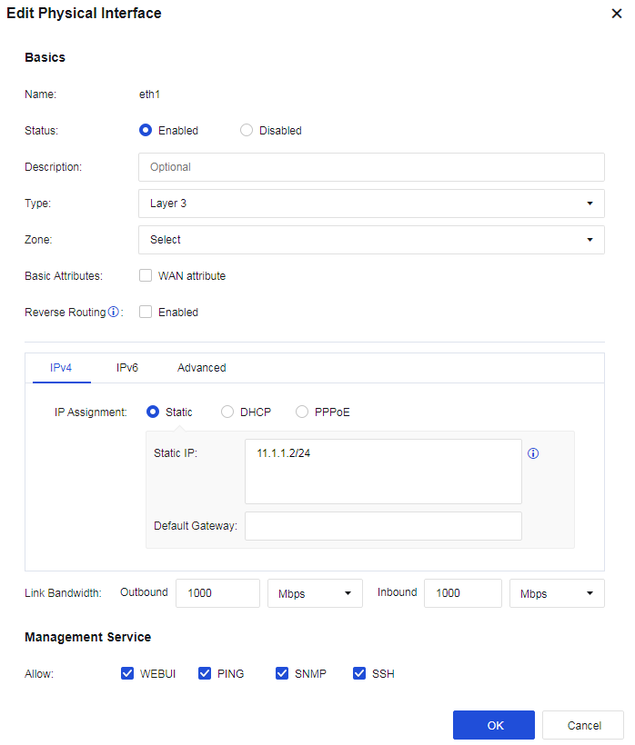
- Enable the HA policy and select the Active/Standby mode for the standby device. Go to System > High Availability and click Settings. On the HA Policy Settings page, check Enable for HA Policy, select Active/Standby as the Mode, select eth1 as the Control Link interface, and set the peer device’s IP address to 11.1.1.1 (the data link is optional in the active/standby mode).
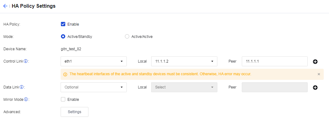
- Set the priority and virtual IP addresses for the standby device. Set Priority to 99. On the Group 0 tab, click Add in the Virtual IP Addresses section. Select eth2 for Interface, and enter 10.2.1.3/24 in Virtual IPv4/Netmask. Then select eth3 for Interface, and enter 10.3.1.3/24 in Virtual IPv4/Netmask, as shown in the following figure.
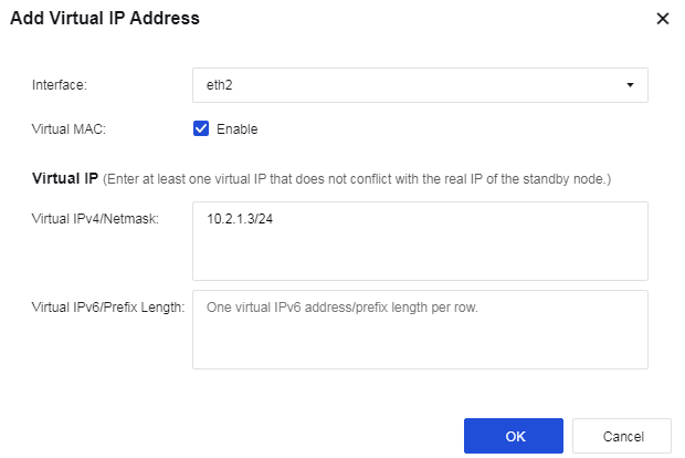
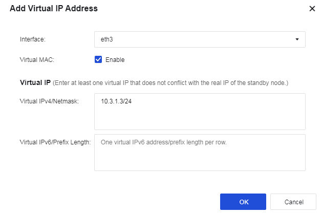
- Configure interface monitoring for the standby device. In the Monitored Object Management dialog box, select the Interface Monitoring tab and click Add. Select One fails for Failure Trigger, select Physical Interfaces for Interface, and select eth2 and eth3 as the service interfaces to monitor.
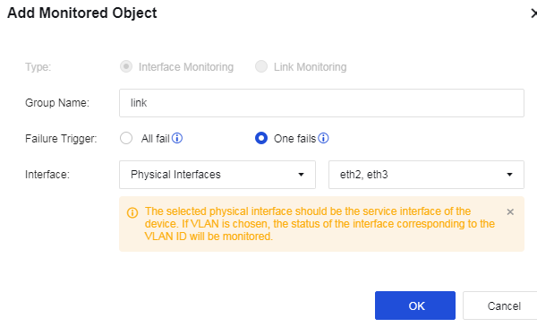
- Associate the monitored object with the standby device. Select the link configured in the preceding step for Monitored Object, as shown in the following figure.
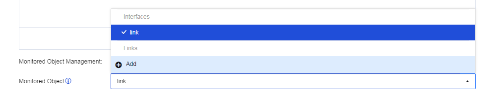
-
Click Save button to save the configuration.
-
After configuring the active and standby devices in the active/standby mode, power on the active Network Secure device and enable its heartbeat interface and service interfaces. Then power on the standby Network Secure device and enable its heartbeat interface and service interfaces. You can go to System > High Availability to view the status of the two HA devices.
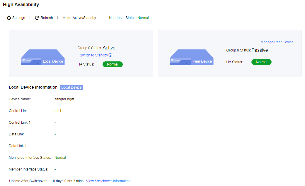
Active/Active Layer 2 Deployment Case
In the active/active Layer 2 deployment, the two Network Secure devices are deployed as bridges within the network (the bridge mode includes the Layer 2 mode and the virtual wire mode). Both devices are active for handling traffic forwarded to them, and their settings and sessions are synchronized through the heartbeat interface.
Configuration Case
An enterprise plans to deploy two Network Secure devices to its LAN in the virtual wire mode. The LAN implements link aggregation based on routers and core switches, and the two Network Secure devices should be deployed as bridges in the active/active mode. As the request and response packets passing through the two devices may be transmitted using different paths, link aggregation is required. The network topology is shown in the following figure.
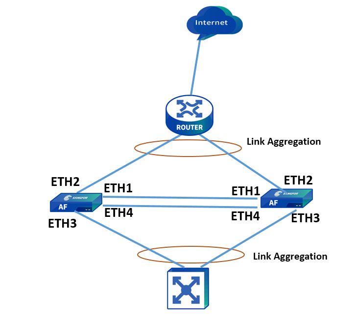
Prerequisites
-
Conditions for an HA deployment: The two devices must have the same software version, memory, interfaces, and licenses.
-
Prepare the service interfaces (LAN and WAN), heartbeat interface, data synchronization interface, and IP addresses for the two devices in advance.
-
Enable the Layer 2 mode and configure related security policies for the active controller.
-
Configure the passive controller after configuring the active controller.
Configuration Procedures
-
Configure the heartbeat interface for the active controller. Go to Network > Interfaces > Physical Interfaces to configure an IP address for the eth1 interface. In this case, the IP address is set to 11.1.1.1/24, as shown in the following figure.
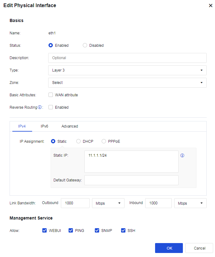
- Configure the data synchronization interface for the active controller. Go to Network > Interfaces > Physical Interfaces to configure an IP address for the eth4 interface. In this case, the IP address is set to 12.1.1.1/24. Enable Jumbo Frame on the Advanced tab, as shown in the following figure.
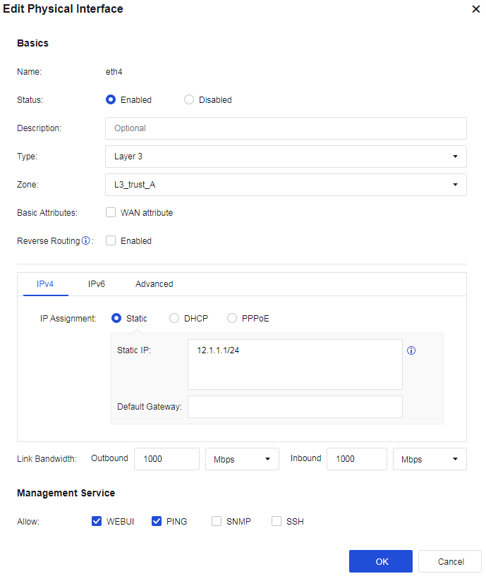

- Configure link state propagation for the active controller. Go to Network > Interfaces > Link State Propagation, select Enable link state propagation and click Add. Select eth2 and eth3, as shown in the following figure.
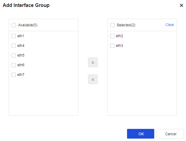
- Enable the HA policy and select the Active/Active mode for the active controller. Go to System > High Availability and click Settings. On the HA Policy Settings page, check Enable for HA Policy and select Active/Active as the Mode. Select eth1 as the Control Link interface and set the peer device’s IP address to 11.1.1.2. Select eth4 as the Data Link interface and set the peer device’s IP address to 12.1.1.2. Enable Layer 2 Mode, as shown in the following figure.
- Configure link aggregation for the active controller. On the HA Policy Settings page, click Settings next to the Link Aggregation field to enter the Link Aggregation dialog box. Add eth3 in LAN Interfaces and add eth2 in WAN Interfaces, as shown in the following figure. Click Save to proceed and the settings meet the conditions for enabling link aggregation.
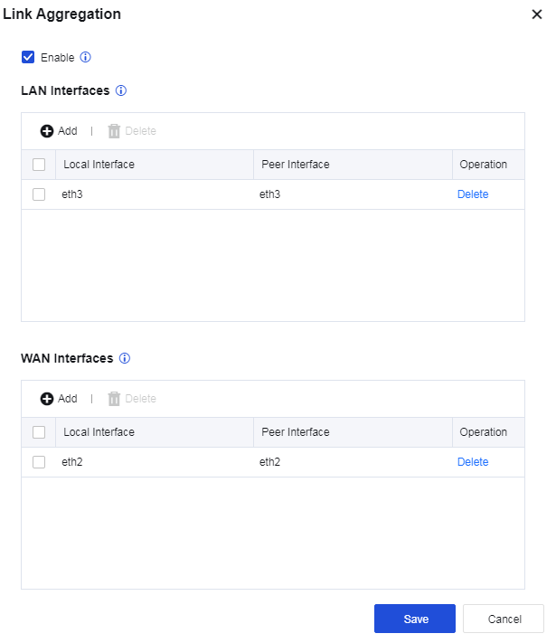
- Assign the active role to the active controller. Go to System > High Availability > Sync Options and click Settings next to the Current Device Role field. Select Active, as shown in the following figure.
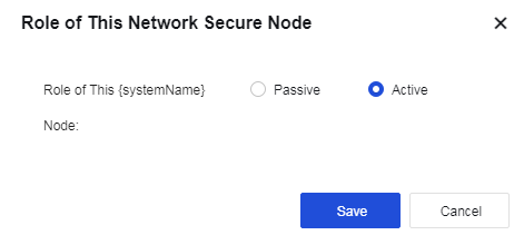
-
Click Save button to save the configuration.
-
Configure the heartbeat interface for the passive controller. Go to Network > Interfaces > Physical Interfaces to configure an IP address for the eth1 interface. In this case, the IP address is set to 11.1.1.2/24, as shown in the following figure.

- Configure the data synchronization interface for the passive controller. Go to Network > Interfaces > Physical Interfaces to configure an IP address for the eth4 interface. In this case, the IP address is set to 12.1.1.1/24. Enable Jumbo Frame on the Advanced tab, as shown in the following figure.
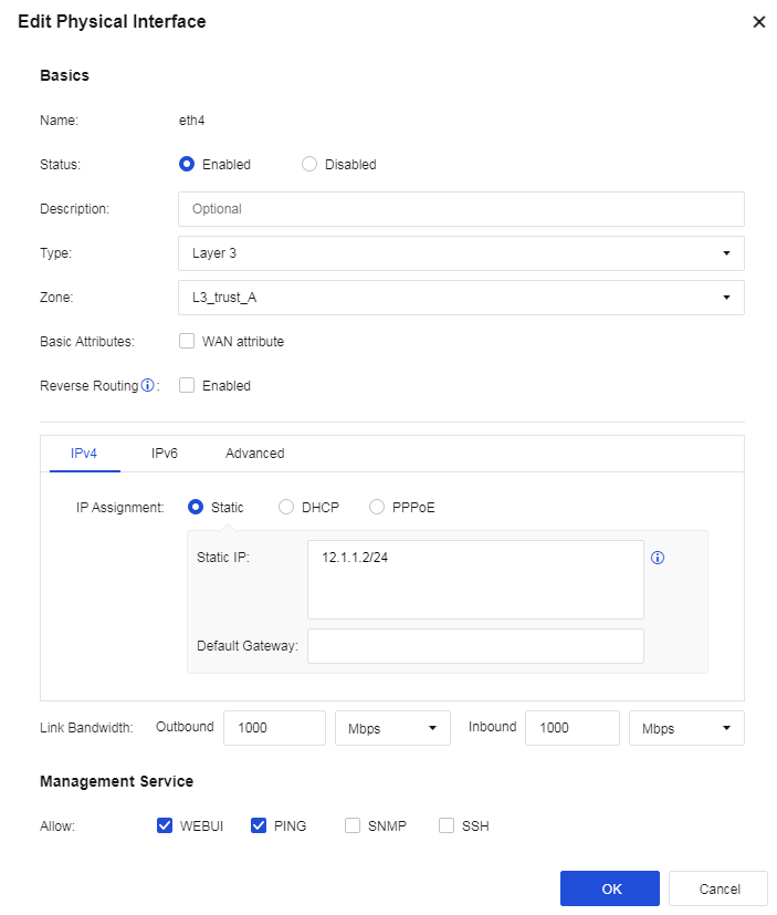
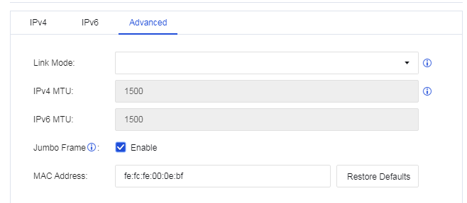
- Enable the HA policy and select the Active/Active mode for the passive controller. Go to System > High Availability and click Settings. On the HA Policy Settings page, check Enable for HA Policy and select Active/Active as the Mode. Select eth1 as the Control Link interface and set the peer device’s IP address to 11.1.1.1. Select eth4 as the Data Link interface and set the peer device’s IP address to 12.1.1.1. Enable Layer 2 Mode, as shown in the following figure.
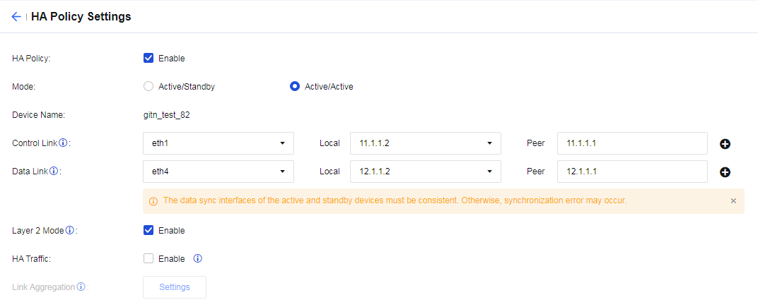
- Configure link aggregation for the passive controller. On the HA Policy Settings page, click Settings next to the Link Aggregation field to enter the Link Aggregation dialog box. Add eth3 in LAN Interfaces and add eth2 in WAN Interfaces, as shown in the following figure.
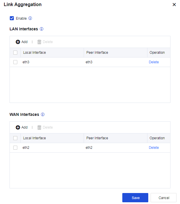
- Assign the passive role to the passive controller. Go to System > High Availability > Sync Options and click Settings next to the Current Device Role field. Select Passive, as shown in the following figure.
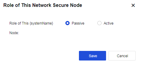
Notice:
- If you deploy Network Secure devices in the active/active Layer 2 mode in scenarios where the request and response packets are transmitted using different paths, link aggregation is required. If the next-hop IP or MAC addresses that Network Secure 1 and Network Secure 2 learned from the upstream and downstream devices are different (the upstream and downstream devices use different routing interfaces), link aggregation and HA traffic are all required.
- Use LACP to aggregate links for the upstream and downstream devices. Change the default MAC-based forwarding algorithm to the IP-based forwarding algorithm for the aggregate interface. Otherwise, the forwarding performance of Network Secure may decrease due to possible asymmetric routing issues.
- Enable Jumbo Frame for the corresponding data synchronization interface when link aggregation is used. One Network Secure device must add the Layer 2 header, Layer 3 header, Layer 4 header, HA header, and Zmode information to a packet before sending it to the other Network Secure device through the control link. In this case, the packet size may exceed the MTU, resulting in packet fragmentation and reassembly, as well as performance degradation. Enabling Jumbo Frame can avoid such issues.
Virtual Systems
A virtual system (VSYS), also called a logical system (LSYS) by some manufacturers, can logically divide a physical firewall into multiple virtual firewalls. Each virtual firewall system can serve as a completely independent firewall device with independent system resources and can provide most firewall features. The virtual firewall systems are independent and cannot directly communicate with each other.
Overview
System Types
Network Secure supports two types of systems:
Public
The public system is a special default VSYS on Network Secure. It exists even if the VSYS feature is disabled. In this case, all settings specified by the administrator for Network Secure apply to the public system. After the VSYS feature is enabled, the public system inherits the existing settings on Network Secure.
The public system manages other VSYSs and provides services for communication between other VSYSs.
VSYS
A VSYS is a logical device that operates independently on Network Secure.
Network Secure ensures accurate forwarding, independent management, and isolation for each VSYS in the following ways:
Resource virtualization: The public system administrator can assign fixed system resources to each VSYS, including interfaces, VLANs, policies, and sessions, which are independently managed and used by the VSYS. Hence, other VSYSs will not be affected when one VSYS is busy.
Configuration virtualization: Each VSYS has its own VSYS administrator and configuration UI (CLI/Web). VSYS administrator can manage only the VSYS to which they belong, and the public system administrator can manage all VSYSs. This streamlines the management of multiple VSYSs and properly enables large-sized networking scenarios.
Routing virtualization: Each VSYS has its own routing tables, which are isolated from each other. This ensures proper communication even if LANs of the VSYSs have the same IP ranges.
Switching virtualization: Each VSYS has its own MAC address tables and ARP tables, which are isolated from each other.
Log isolation: Each VSYS has its own log files and log display UIs.
Therefore, the administrator of each VSYS can use the VSYS as an exclusive device.
Administrator Types
Administrators are classified into public system administrators and VSYS administrators based on the system types.
Public System Administrator
After the VSYS feature is enabled, the existing administrator on Network Secure becomes the public system administrator. The login method, permissions, and authentication method for the administrator remain unchanged. The public system administrator manages and maintains Network Secure and configures public system services.
Only the public system administrator with system management permissions can create, delete, and assign resources to VSYSs.
VSYS Administrator
After a VSYS is created, the public system administrator can add a super administrator and multiple other administrators for the VSYS. The VSYS administrator and public system administrator have different permissions: The VSYS administrator can access only the configuration UI of the VSYS to which they belong, and configure and view only the services of the VSYS. However, the public system administrator can access the configuration UIs of all VSYSs and configure the services of any VSYSs if necessary.
To accurately identify the VSYS to which each administrator belongs, you must set the administrator username in the administrator name@@VSYS name format,as shown in the following figure:
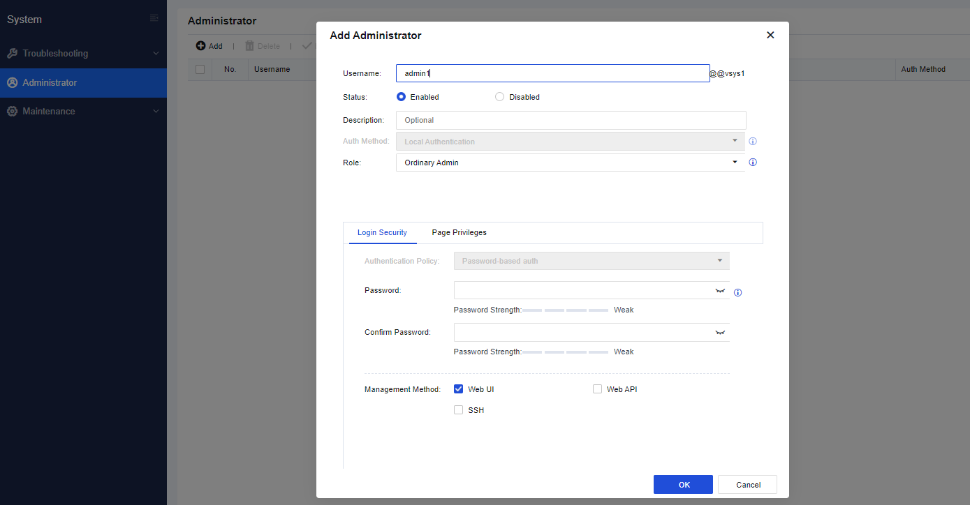
You may access to the virtual system by clicking the Enter System button on the System Management page.
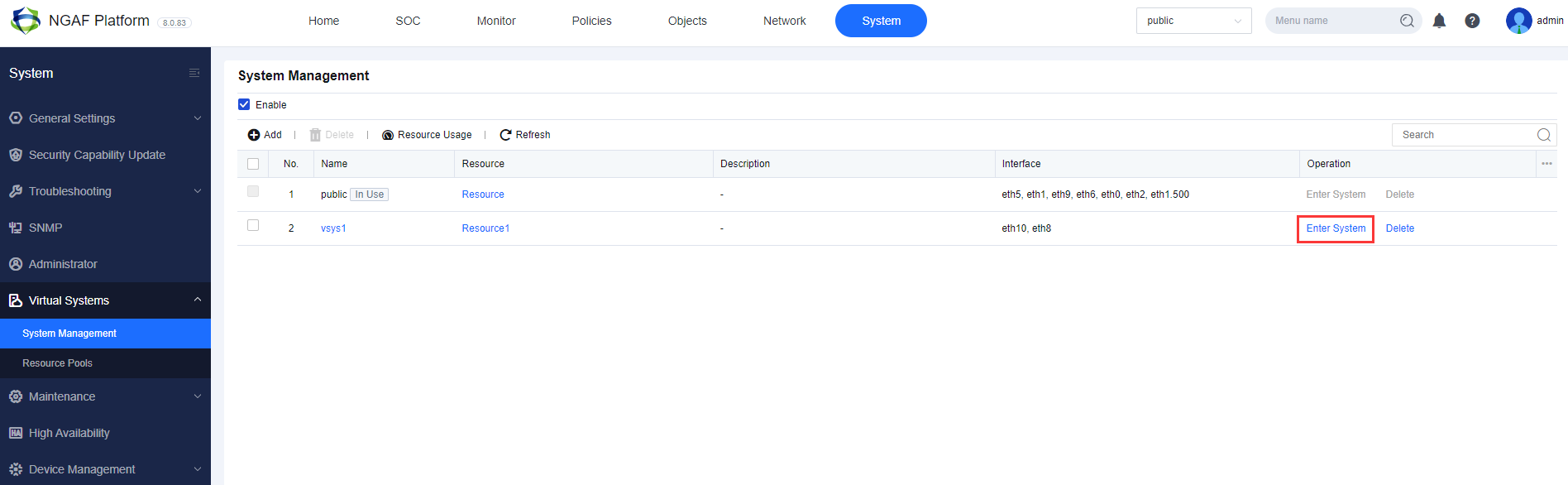
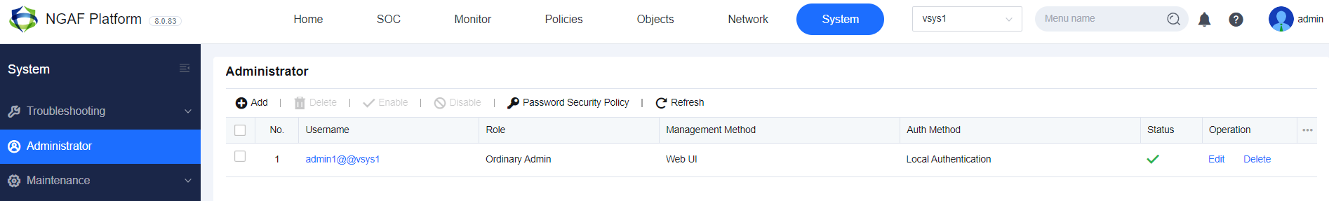
Resource Assignment
Properly assigning resources to VSYSs can prevent a single VSYS from occupying excessive resources and other VSYSs from failing to obtain resources or properly run their services.
Basic resources required for running VSYS services, such as zones, policies, and sessions, support quota assignment or manual assignment.
Quota assignment: This assignment method automatically assigns fixed resources (such as zones, objects, and administrators) based on the system specifications.
Manual assignment: This assignment method allows you to manually assign resources (such as sessions and policies) through the command line or Web UI.
The resources that do not support quota assignment or manual assignment are shared by all VSYSs, and the VSYSs preempt the resources.
The following table describes the resources that support quota assignment and manual assignment.
| Resource | Assignment Method | Description |
|---|---|---|
| Interfaces | Manual assignment | 1. Layer 3 Ethernet interfaces, Layer 3 Ethernet subinterfaces, Layer 3 aggregate subinterfaces, and virtual interfaces can be assigned to VSYSs. 2. Layer 2 interfaces cannot be directly assigned to VSYSs. When you run the assign vlan command to assign a VLAN to a VSYS, the corresponding Layer 2 interface will be assigned to the VSYS along with the VLAN. A Layer 2 trunk interface can be assigned to multiple VSYSs along with the VLAN and configured in each VSYS, for example, added to the security zone. 3. When you run the assign vlan command to assign a VLAN to a VSYS, the corresponding Layer 3 VLAN interface (if any) will be assigned to the VSYS along with the VLAN. You can also directly assign a Layer 3 interface to a VSYS. 4. The eth0 management interface cannot be assigned to VSYSs. |
| VLANs | Manual assignment | When you assign a VLAN to a VSYS, the corresponding Layer 3 VLAN interface will be assigned to the VSYS along with the VLAN. |
| IPv4 Sessions | Manual assignment | |
| IPv6 Sessions | Manual assignment | |
| Application Control Policies | Manual assignment | |
| NAT44 Policies | Manual assignment | |
| NAT66 Policies | Manual assignment | |
| NAT64 Policies | Manual assignment | |
| Local Access Control | Quota assignment | Default: 2 Maximum: 32 |
| Network Objects | Quota assignment | 50-2048, depending on the device model. |
| Services | Quota assignment | Predefined services: 73 Custom services: 512 |
| Schedules | Quota assignment | 64 |
| Zones | Quota assignment | 30 |
| Static Routes | Quota assignment | 512-2048, depending on the device model. |
| Policy-Based Routes | Quota assignment | 256-2048, depending on the device model. |
| Administrators | Quota assignment | Public system: 30 VSYS: 5 (No administrator is configured by default.) |
| Table 24: Resource Assignment Table |
When an administrator manually assigns resources to a VSYS, the administrator configures a resource class, specifies the guaranteed and maximum values for each resource in the resource class, and binds the resource class to the VSYS. The number of resources available for the VSYS is controlled by the guaranteed and maximum values configured in the resource class.
Guaranteed value indicates the minimum number of resources available for the VSYS. After this part of resources are assigned to the VSYS, they are exclusively used by the VSYS.
Note:
- IPv4 and IPv6 sessions of Network Secure are shared resources. For example, if the number of system sessions available is N, the number of IPv4 sessions available is N, and that of IPv6 sessions available is N/2.
- When the number of available (used + guaranteed) sessions is greater than the guaranteed value, the guaranteed value takes effect; otherwise, the guaranteed value does not take effect, and a session will be preferentially preserved when it is released.
- Guaranteed value of policy usage = Maximum value = Maximum number of policies available.
Maximum value indicates the maximum number of resources available for the VSYS. Whether the resource usage of a VSYS can reach the maximum value depends on the resource usage of other VSYSs.
For example, 10 VSYSs are configured on Network Secure. Assume that the total number of sessions available on Network Secure is 500,000, the guaranteed value of session usage for VSYS A is 10,000, and the maximum value of session usage for VSYS A is 50,000. In this case, at least 10,000 sessions can be established in VSYS A, but whether the number of sessions in VSYS A can reach 50,000 depends on the session usage in other VSYSs. If the total number of sessions in the other nine VSYSs and the public system is less than 450,000, you can establish up to 50,000 sessions in VSYS A.
If no resource class is bound to a VSYS, resources of the VSYS are not limited, and such VSYSs and the public system preempt the shared resources available. If the resource class bound to a VSYS does not specify the maximum or guaranteed value for some resources, these resources are not limited, and such VSYSs and the public system preempt the shared resources available.
Shared resources include CPUs, memory, link detection, OSPF, and tables, such as ARP tables and MAC address tables.
Traffic Distribution
Traffic distribution is used to distribute the messages reaching Network Secure to the corresponding VSYSs for processing.
If no VSYS is configured on Network Secure, the messages reaching Network Secure are directly processed based on the policies and tables (session tables, MAC address tables, and routing tables) in the public system. If VSYSs are configured on Network Secure, each VSYS operates as an independent device and processes messages based only on its own policies and tables. Therefore, when a message reaches Network Secure, Network Secure must determine the VSYS to which the message belongs and then forward the message to the VSYS for processing. The process of determining the VSYS to which a message belongs is called traffic distribution.
Network Secure supports interface-based and VLAN-based traffic distribution. Interface-based traffic distribution is applicable to Layer 3 interfaces, and VLAN-based traffic distribution is applicable to Layer 2 interfaces.
Traffic distribution on Layer 3 interfaces
-
Check whether the ID of the VSYS to which the interface belongs is the same as the VSYS ID in the packet context.
-
If not, modify the packet context and forward the packet to the VSYS for processing. If yes, continue to process the packet in the public system.
Traffic distribution on Layer 2 interfaces
-
Check whether the packet carries a VLAN ID.
-
If yes, find the ID of the VSYS to which the interface belongs based on the VLAN ID/VSYS ID mapping table. If not, continue to process the packet in the public system.
-
Check whether the ID of the VSYS to which the interface belongs is the same as the VSYS ID in the packet context.
-
If not, modify the packet context and forward the packet to the VSYS for processing. If yes, continue to process the packet in the public system.
Virtual Interfaces
VSYSs communicate with each other through virtual interfaces.
A virtual interface is a logical interface automatically created for a VSYS upon its creation, which is used by the VSYS to communicate with other VSYSs. The link layer and protocol layer of a virtual interface always remain up. To enable communication between VSYSs through a virtual interface, you must set an IP address for the virtual interface and add it to a security zone so that it can operate properly.
Virtual interface names are defined in vsysif+interface number format. The virtual interface name for the public system is vsysif0. The vsysif interface numbers for other VSYSs start from 1 and are automatically assigned based on the usage of interface numbers in the system.
As shown in the following figure, virtual interfaces of the public system and VSYSs are connected through virtual links. If the public system and VSYSs are treated as independent devices and virtual interfaces are used for communication between them, you can add the virtual interfaces to security zones and configure routes and policies to enable communication between the public system and each VSYS and between VSYSs.
System Management
On the System Management page, you can enable the VSYS feature, add VSYSs, and assign resources, physical interfaces, subinterfaces, and VLAN interfaces to VSYSs.
On the System Management page, check Enable, as shown in the following figure.
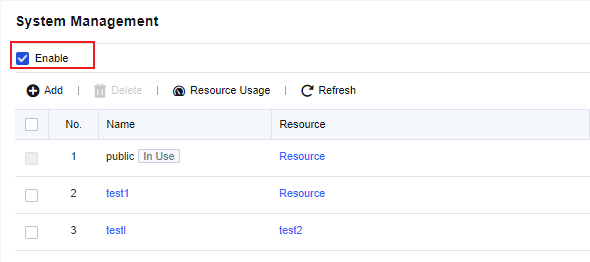
Click Add. The Add Virtual System dialog box appears. On the Basics tab, set a name for the VSYS and select resources from the system, another VSYS, a resource pool, or custom resources, as shown in the following figure.
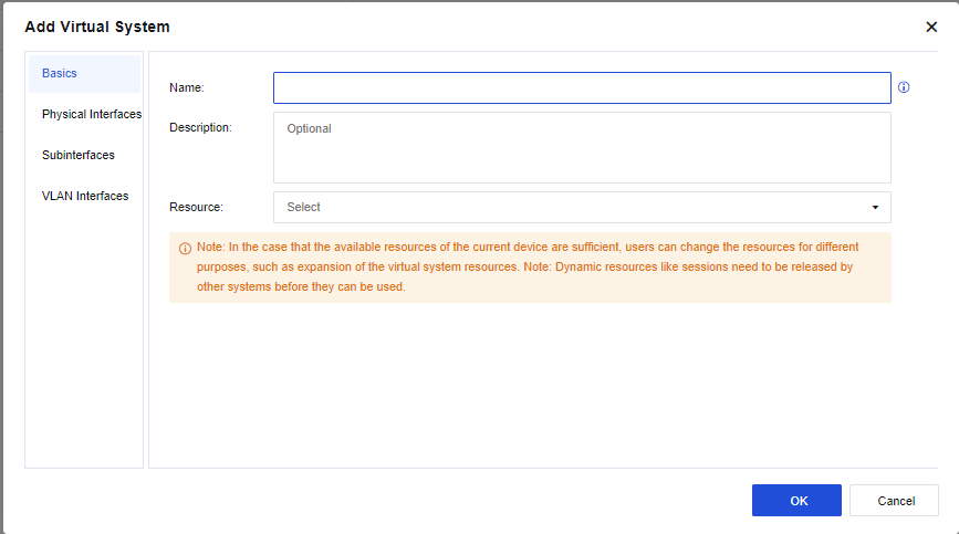
On the Physical Interfaces tab, select physical interfaces for the VSYS, as shown in the following figure.
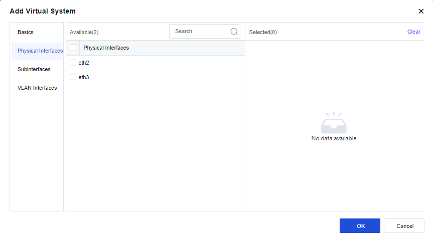
You can also assign subinterfaces and VLAN interfaces to the VSYS on the Subinterfaces and VLAN Interfaces tabs.
After the system is created, the public system administrator can switch to the system in the upper-right corner of the homepage, as shown in the following figure.
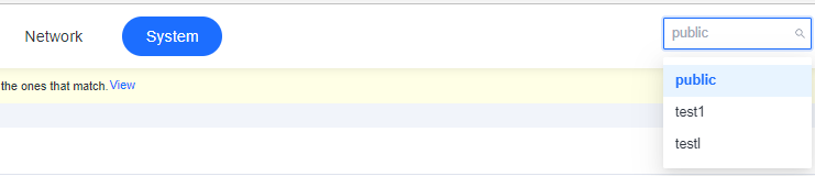
You can create an administrator account for network O&M personnel. Go to System > Administrator. On the Administrator page, click Add. In the Add Administrator dialog box, click Login Security and select Web UI for Management Method. In this way, the network operator can use this account for login.

Example
A company purchased Network Secure and deployed it at the company’s outbound interface as a gateway. The R&D and business networks of the company access the internet through the outbound interface. The subnets of both networks are 192.168.1.0/24. The company requires two virtual firewalls on Network Secure to manage the networks separately, and the networks do not need to communicate with each other. It is also required that the business network can access all internet applications and that the R&D network can only access webpages. The following figure shows the topology.
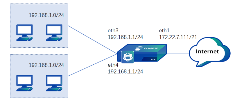
- Go to System > Virtual Systems > System Management. On the System Management page, check Enable.
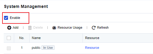
- Click Add. In the Add Virtual System dialog box, set the name to "yanfa" (i.e.R&D), and select resources and a physical interface eth3 for the virtual system. You can use the default resource pool Resource or assign another resource pool as required.
- Click Add. In the Add Virtual System dialog box, set the name to "yewu" (i.e. business) and select resources and a physical interface eth2 for the virtual system. You can use the default resource pool Resource or assign another resource pool as required.
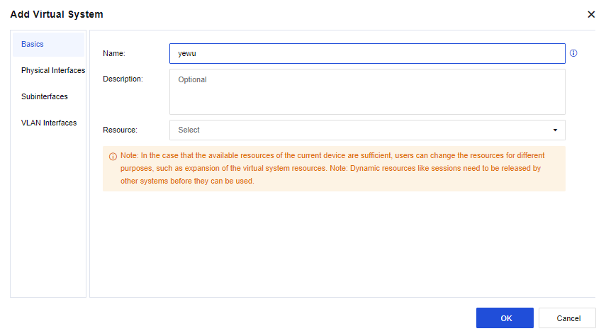
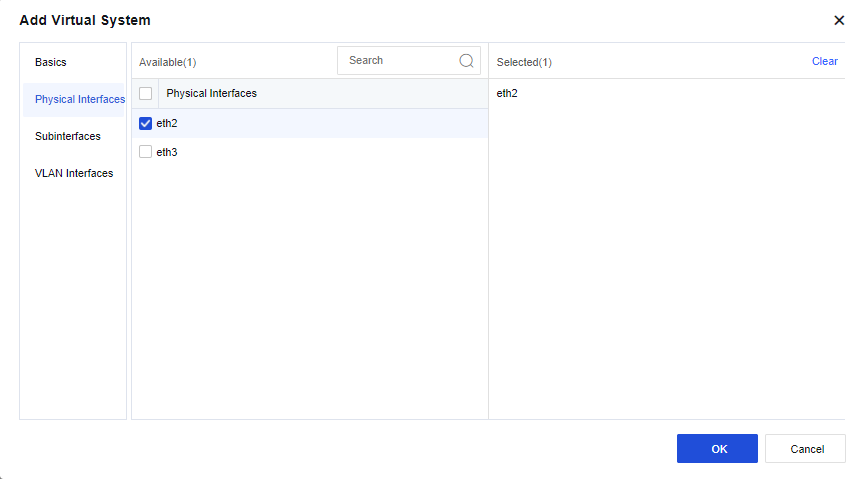
- Switch to the yanfa system and go to Network > Interfaces. On the Physical Interfaces tab, click Edit in the Operation column for physical interface eth1. In the Edit Physical Interface dialog box, select a zone and set the IP address to 192.168.1.1/24.
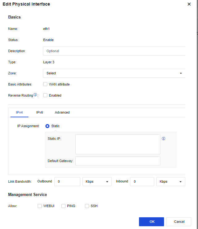
- In the yanfa system, go to Network > Interfaces. On the Virtual Interfaces tab, click Edit in the Operation column for virtual interface vsysif1. In the Edit Virtual Interface dialog box, select a zone and set the IP address to 172.16.1.1/24.
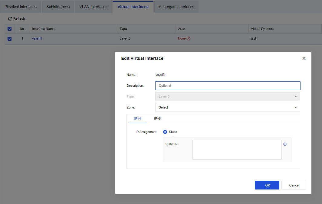
- In the yanfa system, go to Network > Routes > Static Routes. On the Static Routes page, configure a default route directing to the public system of the destination virtual router.
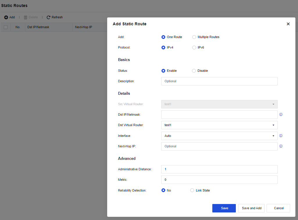
- In the yanfa system, go to Policies > Access Control > Application Control. On the Policies tab, add an application control policy to allow HTTP, HTTPS, and DNS services in the corresponding zone.
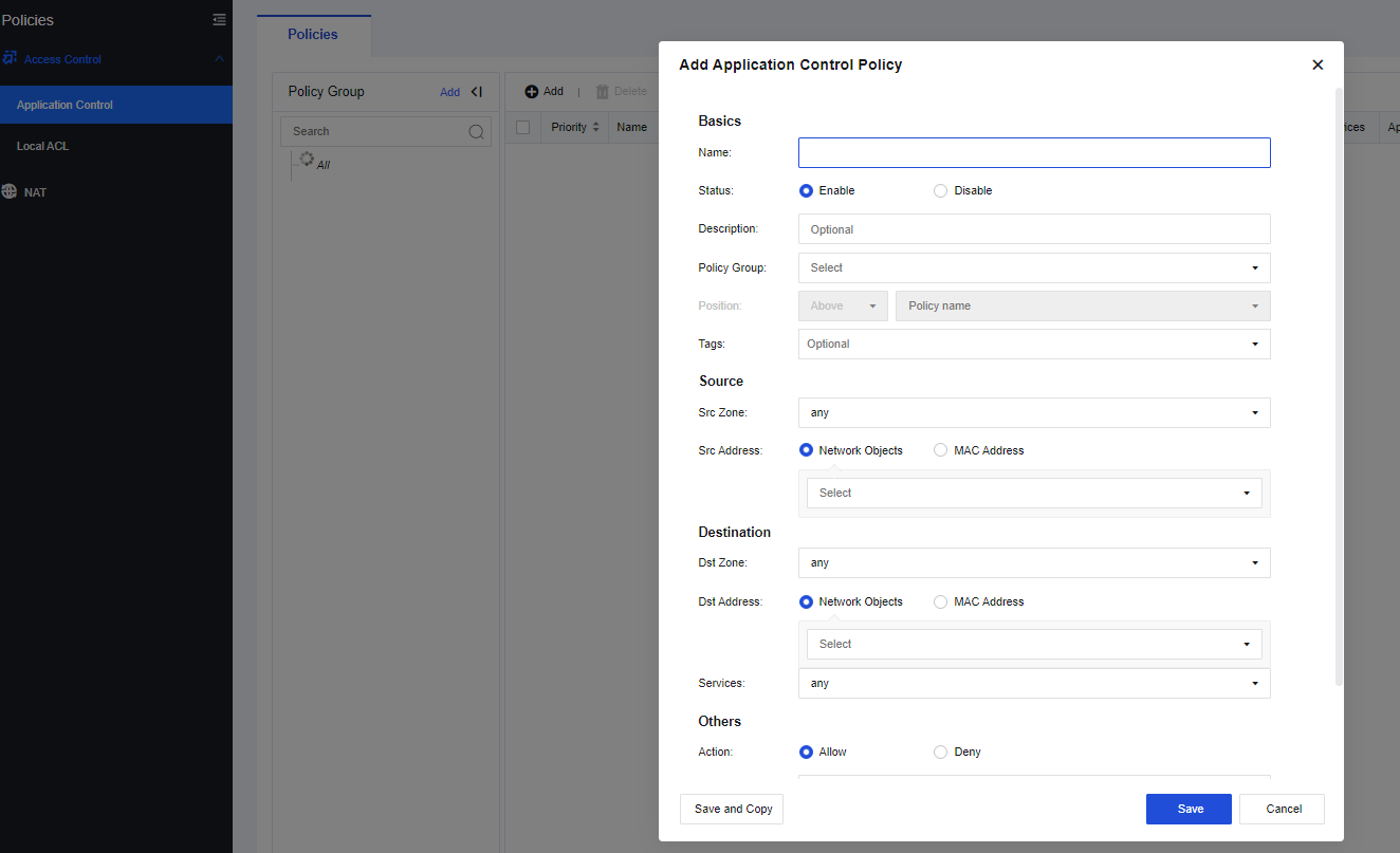
- In the yanfa system, go to Policies > NAT. On the IPv4 NAT tab, add a NAT policy to translate the source IP of the corresponding zone to the address of the outbound interface.
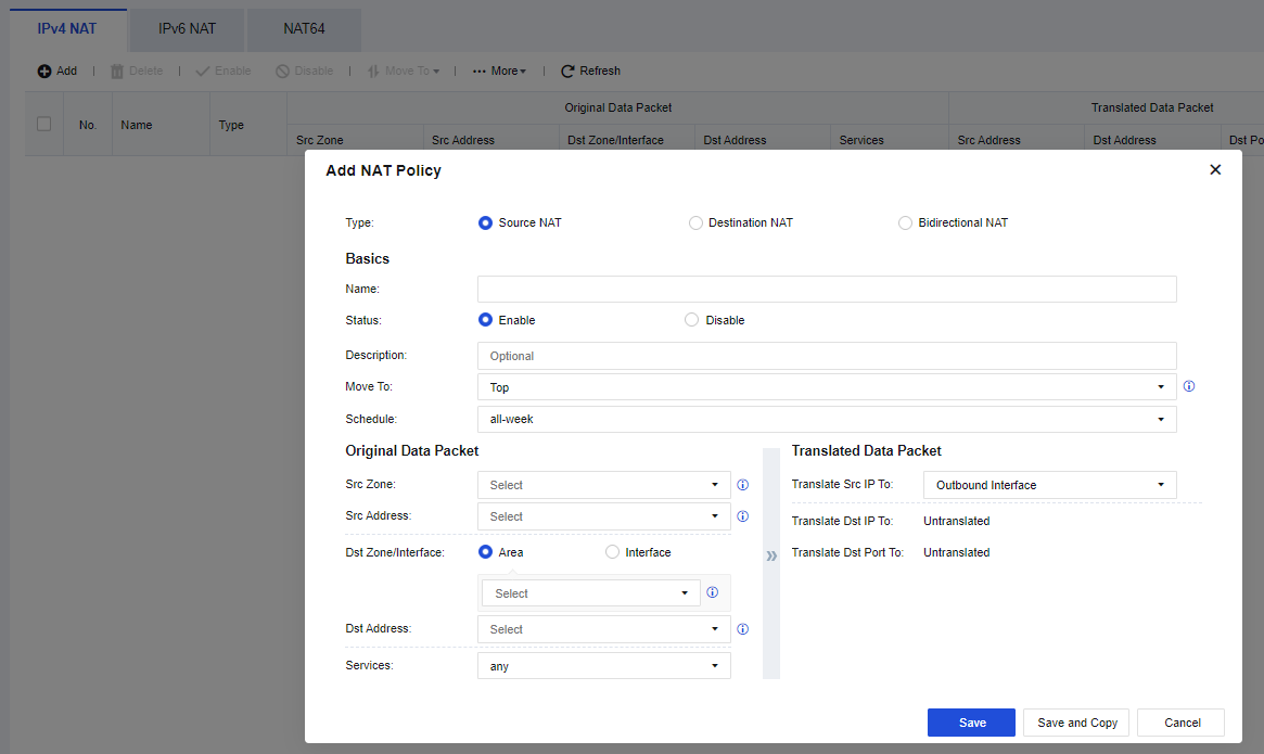
- Switch to the yewu system and go to Network > Interfaces. On the Physical Interfaces tab, click Edit in the Operation column for physical interface eth1. In the Edit Physical Interface dialog box, select a zone and set the IP address to 192.168.1.1/24.
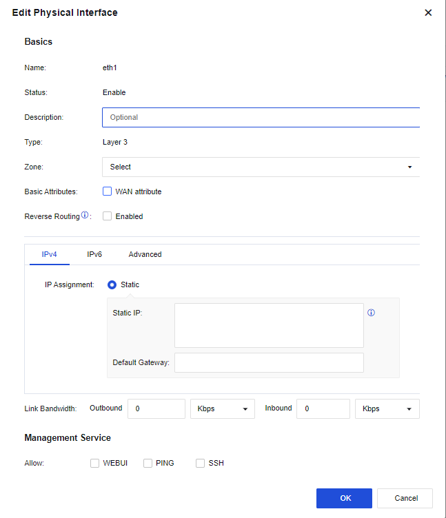
- In the yewu system, go to Network > Interfaces. On the Virtual Interfaces tab, click Edit in the Operation column for virtual interface vsysif2. In the Edit Virtual Interface dialog box, select a zone and set the IP address to 172.16.2.1/24.
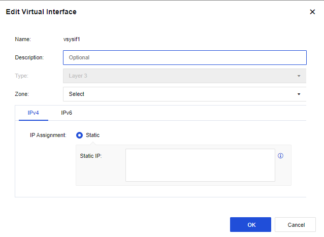
- In the yewu system, go to Network > Routes > Static Routes. On the Static Routes page, configure a default route directing to the public system of the destination virtual router.
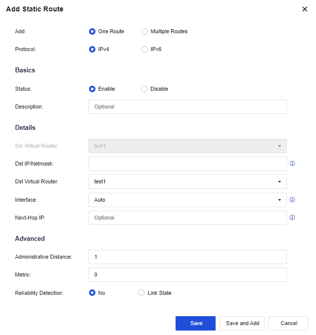
- In the yewu system, go to Policies > Access Control > Application Control. On the Policies tab, add an application control policy to allow all services in the corresponding zone.

- In the yewu system, go to Policies > NAT. On the IPv4 NAT tab, add a NAT policy to translate the source IP to the address of the outbound interface.
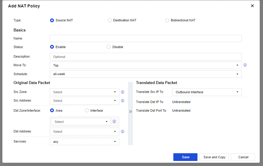
- Switch to the public system and go to Network > Interfaces. On the Physical Interfaces tab, click Edit in the Operation column for physical interface eth1. In the Edit Physical Interface dialog box, select a zone and set the IP address to 172.22.7.111/21.
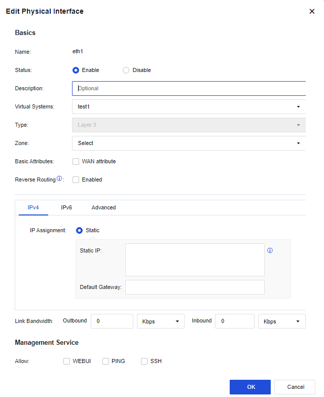
- In the public system, go to Network > Interfaces. On the Virtual Interfaces tab, click Edit in the Operation column for virtual interface vsysif0. In the Edit Virtual Interface dialog box, select a zone and set the IP address to 172.16.3.1/24.
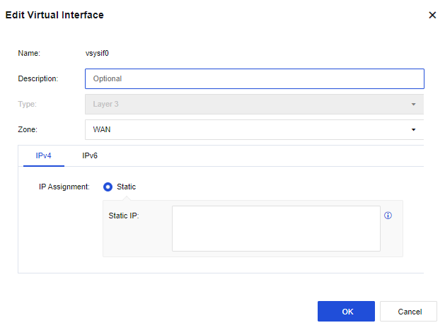
- In the public system, go to Network > Routes > Static Routes. On the Static Routes page, configure a default route directing to the next-hop outbound interface of the internet and static routes respectively directing to the yanfa and yewu systems, with the destination IP set to the addresses of interfaces vsys1 and vsys2.
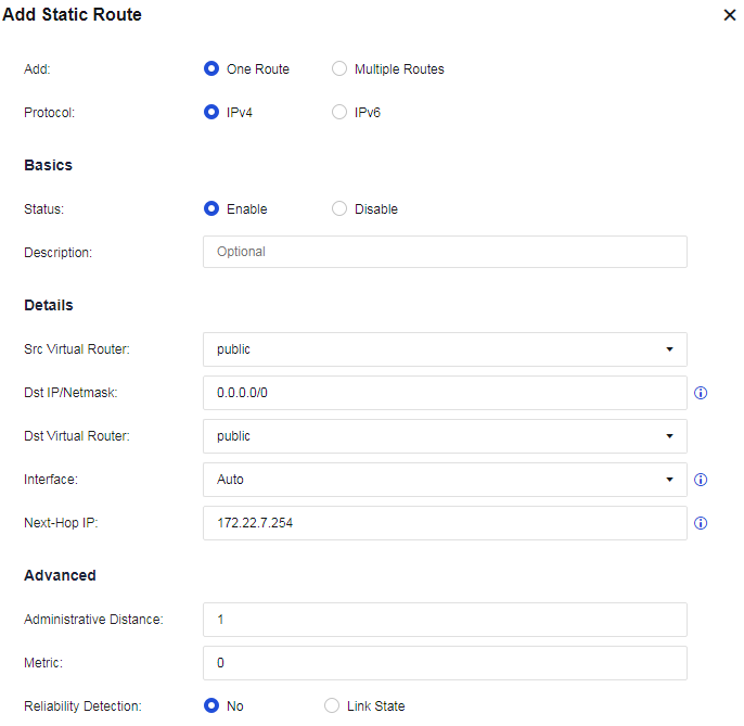
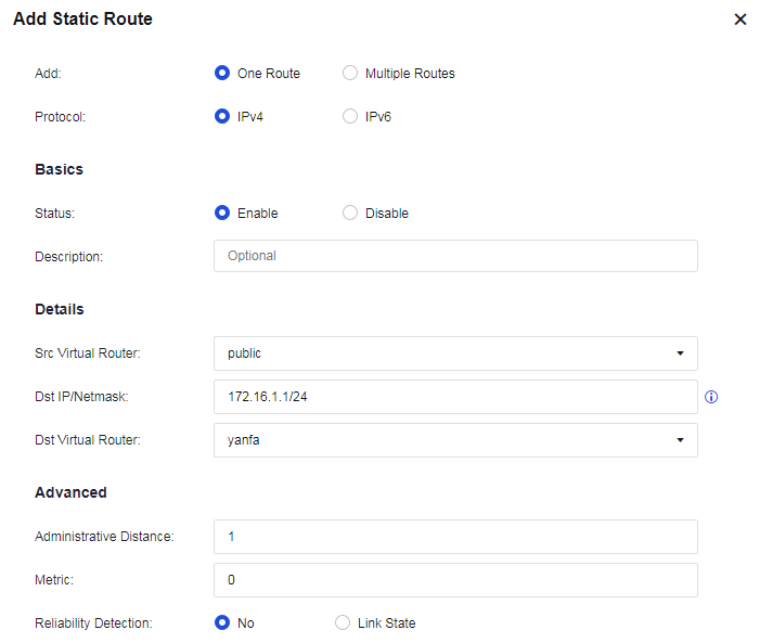
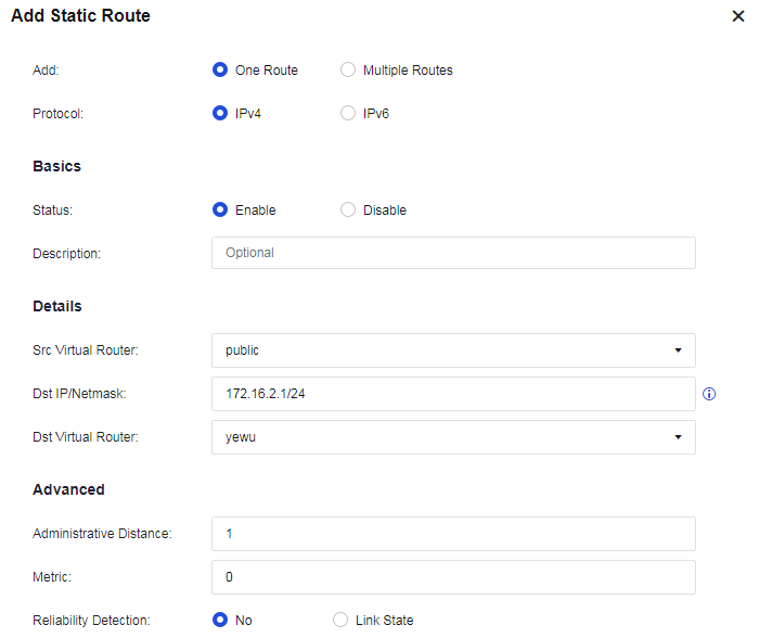
- In the public system, go to Policies > Access Control > Application Control. On the Policies tab, add an application control policy to allow all services in the corresponding zone.
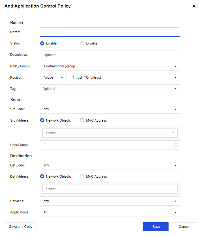
- In the public system, go to Policies > NAT. On the IPv4 NAT tab, add a NAT policy to translate the source IP to the address of the outbound interface.
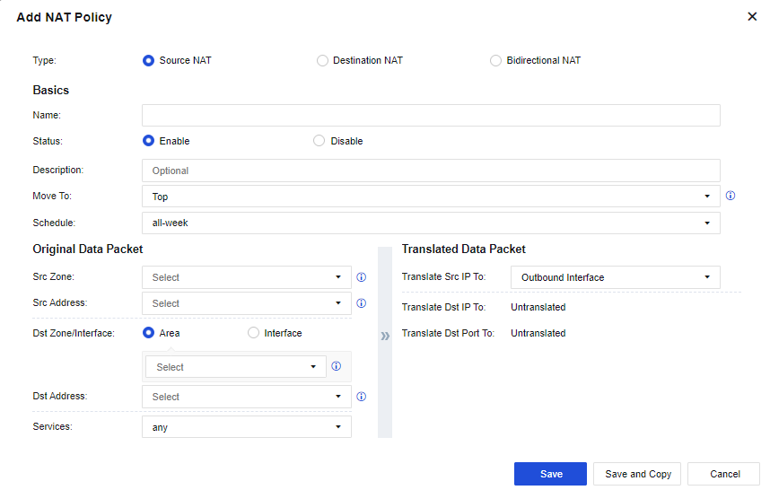
- Verify network access on the R&D and business networks.
Resource Pools
You can set the guaranteed and maximum values for manually assigned resources in a resource pool so that a VSYS can call the resource pool.
On the Resource Pools page, click Add. In the Add Resource Class dialog box, set the parameters as required, as shown in the following figure.
Device Management
Central Management
To enable the Network Secure device to join the Central Management Platform for management. After the device joins the platform, the administrator can configure policies for this device and the Central Manager can grant permissions to the controlling terminal. The device is allowed to join in Central Manager.
Network Secure Settings
Status: Specify whether the device has connected to the Central Management Platform.
Remove from Central Management Platform: Enter the password for removing the device from the Central Management Platform. The administrator of the Central Manager keeps the password. This function is available after the device is connected to the platform.
Central Manager/Platform-X Address: Specify the device’s IP address to be connected to the Central Management Platform. The administrator of the Central Manager keeps the IP address.
Click Test Validity to detect whether the IP address and port number are available.
Device Name: Specify the username for the Central Manager of the Central Management Platform.
Password: Specify the password for connecting to the Central Manager of the Central Management Platform.
Shared Key: Specify the shared key of the device. This parameter is optional.
Central Management Settings
To connect a Network Secure device in Shenzhen to the Central Manager device for management, follow the configuration guidance.
Configuration Guidance
- Log in to the Central Manager console, go to the Branches tab, specify the region name, and click OK to save the setting.
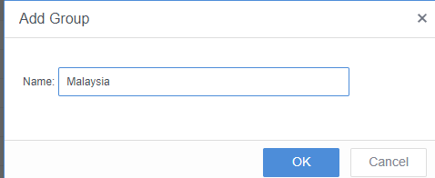
- Select the region that you just created, and click New.
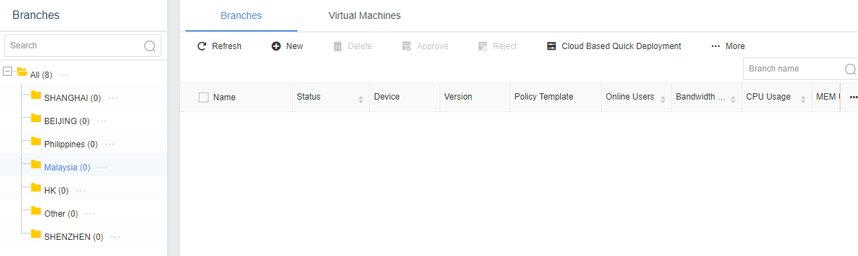
- Set the Branch Name, Branch Device(s), Access Token, Geo Location, and Group parameters, and then click OK.
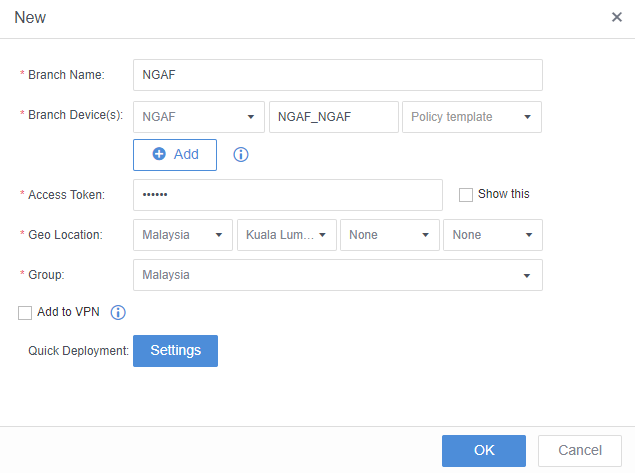
- Log in to the Network Secure device, navigate to System > Device Management > Central Management, and select Joined to the central management platform. Enter the IP address suffixed with :5000 (IP address of the Central Manager device) in the Central Manager/Platform-X Address field, enter the name of the branch device in the Device Name field, enter the password for connecting to Central Manager in the Password field, and then click Save.
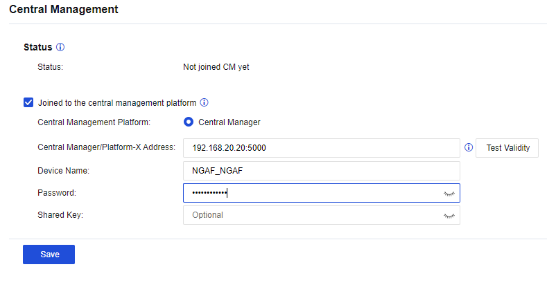
- The The device has connected to Central Management Platform status indicates that the Network Secure device has connected to Central Manager successfully.
QAssistant
QAssistant provides diagnostic analysis of device operating metrics. It offers real-time monitoring and alerts to assist experts in preventing and fixing risks, which helps avoid impacts on your business.
When your device cannot access the Internet, you can connect to the QAssistant client to transmit data to QAssistant, as shown in the following figure.
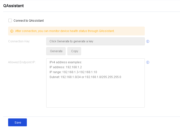
Integration Bus
Integration Bus allows you to seamlessly integrate Network Secure with Omni Command, Endpoint Secure, and other products or integrate Network Secure into Central Manager on the central management page. You can connect to the integration bus by entering authentication information, such as the corporation ID, as shown in the following figure.
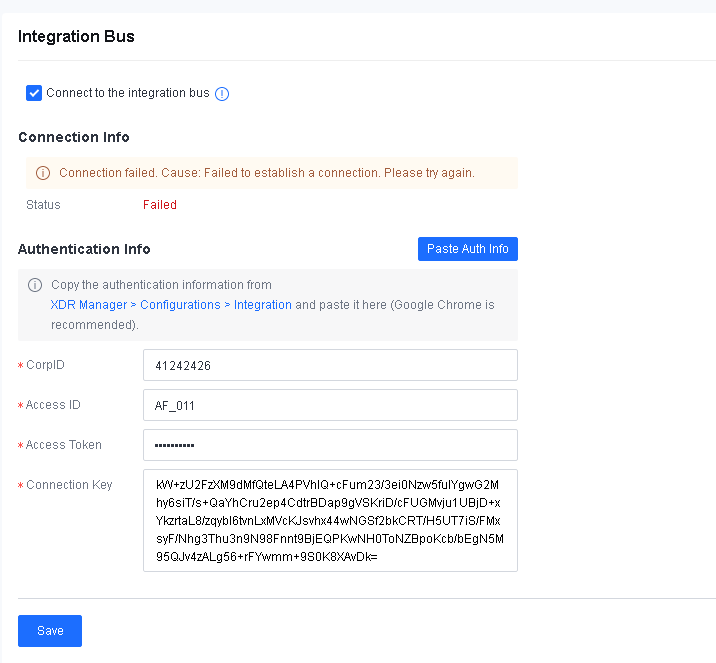
O&M Management
This chapter describes the O&M management of the product and guides the administrator in performing routine maintenance on the devices and simple troubleshooting.
Routine Inspection
| Item | Description |
|---|---|
| Transferring the device | Disconnect all power cables and external cables before moving the device. |
| Installing the device | 1. Install the tray or guide rail for the NSF 2U device. 2. Install the device on a clean workbench if no standard cabinet is available. Ensure the workbench and cables are rigid for the device, with 10 cm space reserved around the device for heat dissipation. 3. Do not place heavy objects on the device. 4. When installing, take note of other devices in the same cabinet, and do not remove the power unit and network cable interfaces of other devices. |
| Installing mounting ears | After installing the tray or guide rail for the device, the mounting ears may not be properly installed. Install the ears in other cases. |
| Wiring the power unit | Connect the redundant power unit (if any). |
| Cabling | 1. When laying aisle cables, bind them. The bound cables should be close to each other, with a straight and tidy view. The cable ties are spaced evenly and tightened moderately. When laying channel cables, do not bind them. 2. Route signal cables, pigtail fibers, and power cables separately if possible. Do not keep them close, and do not bind them. Bind cables in the cabinet straight and neatly, without winding and binding. 3. Check whether there are burrs, sharp edges, or sharp corners near the area close to the routing area of the fibers before binding the pigtail fibers. If so, try to avoid them. Install a fiber protection sleeve (a corrugated pipe) when wiring outside the cabinet. |
| Label | Cables must be labeled. 1. Label for power cables: The text is the information of the corresponding position of the cable. Fill in the position information of the corresponding device, control cabinet, distribution box, or socket where the label is located. 2. Label for signal lines: The two sides of the label respectively provide the position information of the port connected to both ends of the signal line. 3. Fill in or print the label text on the full-page label paper before attaching the label, and then peel off and paste it on the cable or the identification card on the cable tie. |
Table 25: Routine Inspection Description
Check the Hardware of the Device
When a Sangfor Network Secure hardware device is working normally, the POWER indicator light stays on. The ALARM indicator light stays on for a long time (about one to five minutes) only when the equipment is started due to system loading and is off during the normal operation of the device. If the ALARM indicator light stays solid red during use and the device is not working properly, follow the steps below:
-
Turn off the device immediately, and switch the system to the standby device.
-
Restart the device after half an hour. If the ALARM indicator light still stays on after the restart, contact Sangfor Technical Support in time to determine whether the device is damaged.
-
The other indicator light on the device is the HA indicator light, which may be on only in the dual state. Suppose the device is deployed in dual-machine hot standby mode. The HA indicator light of the standby device regularly flashes to indicate the current state.
Check the Interface Indicator Light
Under normal circumstances, while sensing electrical signals, the LINK indicator light of the network interface remains solid green in a 100-megabit link, but solid orange in a gigabit link. The ACT indicator light of the network interface is in orange and flashes continuously in data transmitting. If the LINK or ACT indicator light does not flash or fails to be on, follow the steps below:
-
Check whether the network cable is damaged.
-
Check whether the registered jack of the network interface is damaged.
-
Check whether the NIC duplex mode is negotiated and matched.
-
If none of the said problems exists, restart the device, switch to the standby device, and contact Sangfor Technical Support in time.
Check the Running Condition of the Device
Check whether the usage ratio of the CPU, memory, and disk is high for a long time according to the system status on the device console. If so, follow the steps below:
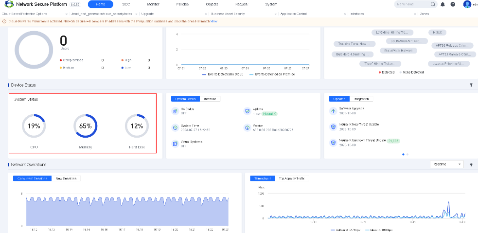
Note:
After logging in to the device, the first page will show the system status.
-
Navigate to Home > Network Operations > Throughput and check whether the current bandwidth is in full load all the time.
-
Navigate to Home > Network Operations > Concurrent Sessions/New Sessions and check whether the emergency concurrent sessions or new sessions are generated.
-
Enable the Anti-DoS attack module for the device and check whether the device is suffering from DoS attacks. Go to Monitor > Logs > Security Logs to view the anti-DoS attack logs.
-
Check whether any process runs abnormally. (Contact Sangfor Technical Support for confirmation.)
Check the Abnormal Status of the Device
Check whether an abnormal noise arises from the device’s hardware, such as a fan or hard disk.
If an abnormal noise arises from the inside of the device, the hard disk or fan may work abnormally. Turn off the device immediately, and switch the system to the standby device immediately (if any). Contact Sangfor Technical Support to determine the fault, and return the device for repair.
Check the Configuration Information of the Device
Device Configuration Backup
To ensure stable operation of the network, we recommend that you back up the configuration monthly to restore the Network Secure system upon unexpected breakdown rapidly.
Method: Log in to the Network Secure console, and navigate to System > Maintenance > Backup/Restore. Then click Download to download the configuration and save it properly, as shown in the following figure.
Check the Version of the Rule Database
To ensure that the device can correctly identify the latest network applications, we recommend that you periodically check whether the rule database of the device is up to date. If the update is abnormal, check whether the device can access a public network.
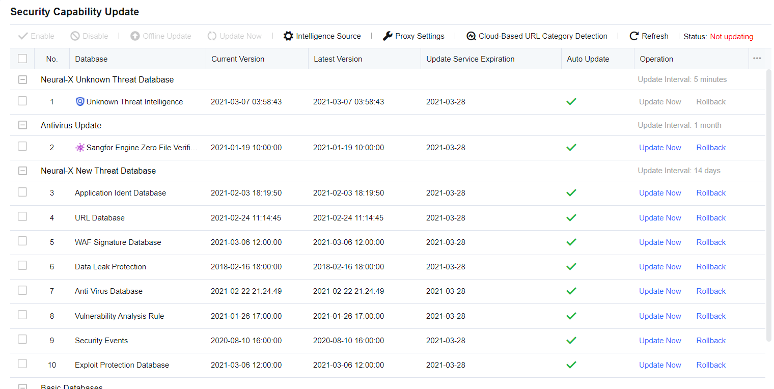
Check the Security of the Device
Check the Security of the Console Account
-
Check whether the password of the console admin account is a simple password such as the default "admin" or "123456". Change the default password or a simple password immediately.
-
Check whether the password of the console admin account remains unchanged within one month. If so, change the password immediately and keep it safe.
-
Check whether the console has redundant accounts, such as "Sangfor", "test", company name in English, and other simple undesired accounts. If so, delete the redundant accounts, and keep the authorized admin account only.
Check the Remote Maintenance Status of the Console
Navigate to Network > Interfaces to view the management service and check whether the remote maintenance status of the device is enabled to prevent the device from being accessed by unauthorized personnel from a public network interface.
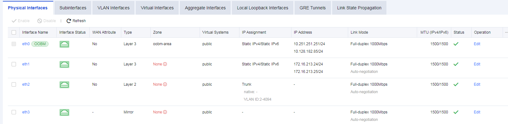
Check the Log Information of the Device
Navigate to System > Troubleshooting > Logs to view the operating status logs of each module of the device. With these logs, you can determine whether the modules of the device are running normally.
The system logs include three types: Info, Warning, and Error. On the Logs page, click Options to enter the Settings dialog box. Select the checkboxes under Logging Options to filter the type and the module to be displayed.
If a large number of logs in the Error and Warning types exist in the system logs, contact Sangfor Technical Support in time to check the programs of the device for failures.
Shortcut Functions
This section introduces some shortcut functions on the console page, which help the administrator manage the console with ease. These functions mainly include menu search, vulnerability CVE search, and quick tab.
Menu Search
To rapidly find a corresponding function menu by searching for a keyword.

- Enter the keyword of a function menu you want to search in the search box, such as "security". Then, menu items related to this keyword appear, as shown in the following figure.
- Select the function menu, such as Security Capabilities. Then, the Security Capabilities page appears, as shown in the following figure.
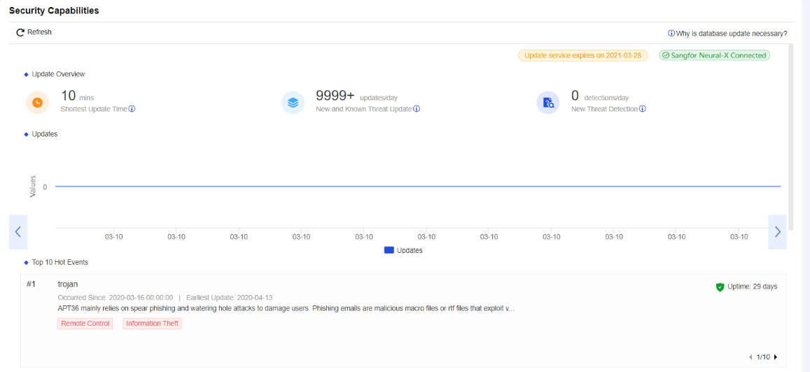
Vulnerability CVE Search
To search local vulnerability rules of Network Secure and view whether the protection is enabled for this vulnerability.
- Go to Home > Quick Links and click CVE Search, as shown in the following figure.
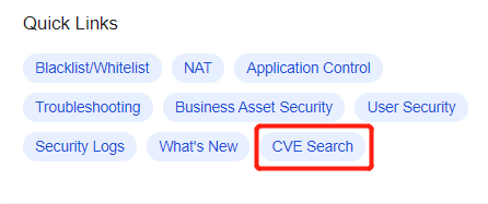
- In the CVE Seach dialog box, select Vuln Name or CVE ID from the drop-down list to view the vulnerability, as shown in the following figure.
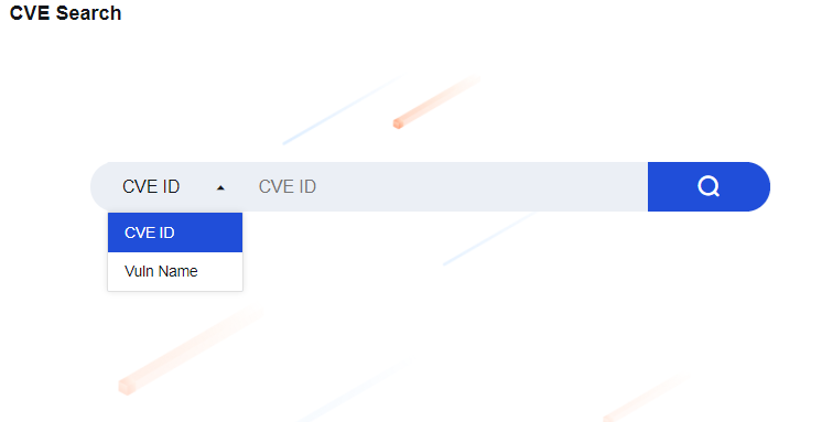
- Enter information to be queried in the search box, such as CVE-2018-17208. Click the search icon, as shown in the following figure.
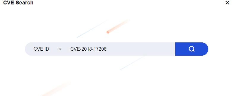
- If the local rule database does not contain CVE-2018-17208, the Message dialog box will appear. You can click Go to Sangfor Security to enter the Sangfor Security Center page for queries. See the figure below.
- If the local rule database contains CVE-2018-17208, the search result page appears, as shown in the following figure.
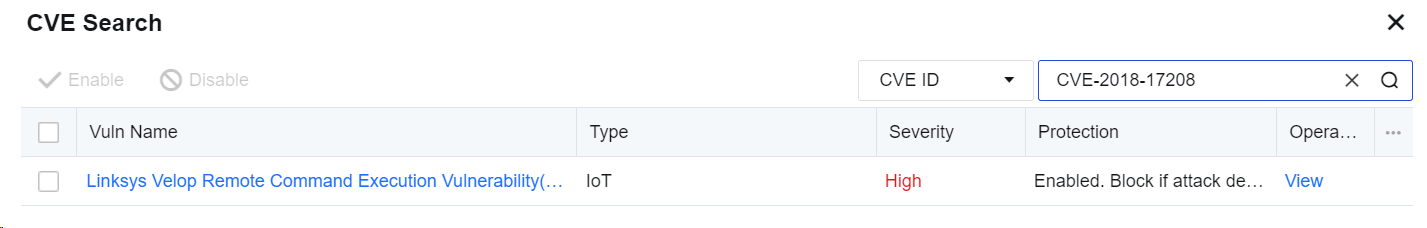
- Click View in the Operation column to enter the CVE Search page and view the specific protection situations. Click View Details to redirect to the Sangfor Security Center page. Then, click View Details to go to the vulnerability rule page.
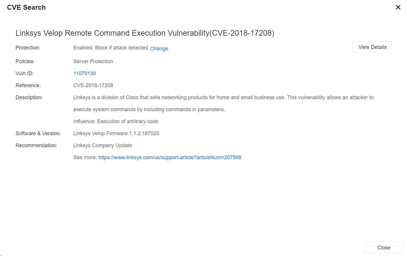
Notice:
When selecting CVE ID to search for a vulnerability, you can search it only if a full CVE ID is entered, such as CVE-2018-17208, but you are allowed to use fuzzy search. When selecting Vuln Name to search for a vulnerability, you can enter a keyword for a fuzzy search.
Page Shift
To set the page shift for a menu function. When clicking the page shift, you can directly go to the configuration page of this menu function. This helps the administrator manage the console with ease.
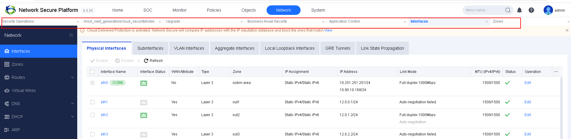
Restoration of the Device Configuration and Password
This section describes how to restore related configurations, passwords and the specific scenarios.
Restore the Password by Rebooting with a USB Flash Drive
This section describes how to restore the default password "admin" of Network Secure’s default admin account "admin" using a USB flash drive.
Applicable Scenarios
The admin account password is lost, and no other account is available, making the user unable to log in to the console and the background. However, the IP address of the device is available.
Operation Procedure
The Network Secure device supports the restoration of passwords by using the USB flash drive based on the following steps:
-
Create an empty file named "reset-password.txt" in the root directory of the USB flash drive.
-
Insert the USB flash drive, and restart the device.
-
When the device can log in to the console normally, remove the USB flash drive.
-
Check the result file named "reset-password.log" in the USB flash drive. If the restoration is successful, the restored password of the console should be recorded in the file. Otherwise, the restoration failure is recorded.
Notice:
- You can create a blank text file on the Windows system and rename it for the corresponding function.
- The text file must be in the root directory of the USB flash drive.
- The USB flash drive can contain one or multiple partitions. The USB flash drive with one partition must be in the FAT32 format. For the USB flash drive with multiple partitions, the txt file must be stored in the first partition in the FAT32 format.
- The three functions mentioned above are not exclusive to each other. You can perform multiple operations simultaneously.
Restore the Factory Settings
This section describes how to restore the factory settings of the Network Secure device on the console page.
Applicable Scenarios
If you can normally log in to the device, you can restore it to the factory state directly on the Web UI console of the device.
Operation Procedure
Log in to the Network Secure console, go to System > Maintenance > Backup/Restore, click Restore to Factory Defaults or Restore Configuration, and then operate as prompted.
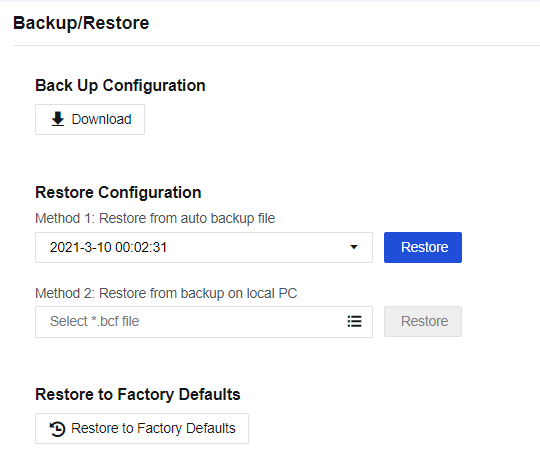
Notice:
If you select Restore to Factory Defaults, the device will be restarted. Make sure whether the device can be disconnected from the Internet before restoring. We recommend that you restore the configuration when no services are running or in the low-peak period of services to avoid impacts on normal services.
Patch Update Guidance
Methods to Obtain Sangfor Patch
Sangfor provides five patch-obtaining methods for different scenarios:
-
If the device can access the online patch server, it can automatically obtain a patch.
-
If the device accesses the WAN using a proxy server, configure the proxy server to obtain a patch.
-
If the device cannot access the WAN, configure the Sangfor OLU LAN patch server to obtain a patch.
-
If the device cannot access the online patch server, but the PC accessing the device control platform can access the Internet, access the Sangfor online patch server with the PC browser to obtain a patch.
-
If the device cannot access the online server and your PC cannot access the Internet, scan the QR code by using your mobile phone to obtain an offline patch.
Check Links
Confirm the networking conditions of the device in the following five scenarios:
-
The device can access the Internet normally and directly have access to the Sangfor online patch server.
-
The device cannot directly access the Internet but uses a proxy server to access the Internet and update the rule database.
-
The device is offline but able to use the OLU LAN patch server to obtain patch updates.
-
The device is offline and unable to use the OLU LAN patch server, but the PC accessing it can access the Internet.
-
Both the device and PC accessing it are offline and the device cannot use the OLU LAN patch server.
Confirm the configuration of the update server. You can set the update server in one of the following three ways:
-
Manually enter the server IP address: Manually enter the IP address of the OLU LAN patch server. Then, you can obtain a patch for the update from the server. (At present, the OLU LAN patch server supports only patch update, rather than rule database update.)
-
Automatically select the server IP address: The device will perform the polling process for online update servers available for Sangfor devices to select an optimal one for obtaining updated information automatically.
-
Select a specific server IP address: Obtain update information from the specified online patch server.
Scenarios and Configuration
This section describes how to update the patch in the five scenarios.
Device Able to Access Internet and Automatic Patch Update Enabled
If the device can access the Internet and the automatic patch update is enabled, you do not need to do anything and view the updated patch.
Log in to the device as the administrator, navigate to System > Maintenance > Service Packs to enter the Service Packs page, and view the updated patch.
Device Able to Access Internet and Automatic Patch Update Not Enabled
Suppose the device can access the Internet and the automatic patch update is not enabled. In that case, the device can automatically obtain an update patch which can only be installed manually.
-
Log in to the device as the administrator, navigate to System > Maintenance > Service Packs to enter the Service Packs page, and view the patch update list.
-
Click Install Now to install the patch.
-
View whether the patch is installed successfully.
Notice:
We recommend enabling the Automatic Patch Update function. You will be reminded when the device is restarted or update for patches in other particular scenarios is required. These patches can be updated only after you confirm the update information manually.
Device Using Proxy Server to Obtain Patch Update
Suppose the device cannot access the Internet, but a LAN server serves as a proxy to access the Internet. In that case, you can set a proxy server, allowing the device to access the Internet using the LAN proxy server and update the patch.
After the proxy server is configured and the device can use it to access the WAN normally, the device can obtain a patch by following the same steps as those in the preceding two scenarios. This section only describes how to configure a proxy server.
- Go to System > Maintenance > Service Packs and click Settings, as shown in the following figure.
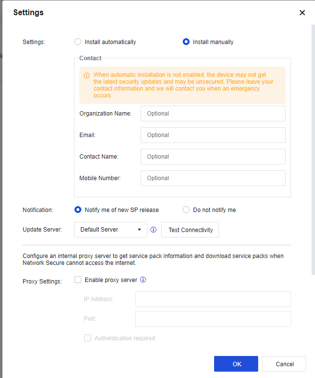
- Select Enable proxy server and enter the IP Address and Port of the proxy server. If the username and password are required when the device connects to the proxy server, select Authentication required and enter the Username and Password to be verified by the proxy server. Users provide the username and password.
Both Device and PC Unable to Access Internet
If the device cannot access the online server and your PC cannot access the Internet.
- You can log in to the device and go to System > Maintenance > Service Packs, and click How to Get SPs. Follow Method 3 to contact our Sangfor Technical Support team.
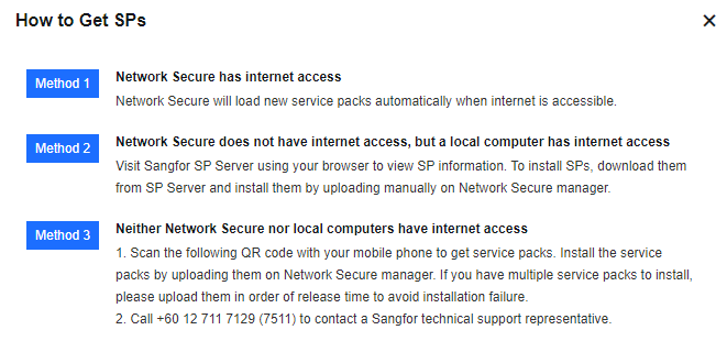
Precautions
-
If the device cannot access the Internet, establish an OLU server in the LAN for users.
-
If the users disagree with using the LAN OLU server, they can select the browser proxy or QR code scanning method to obtain a patch.
-
After the configuration for the update is completed, they must scan the QR code to report the device information.
-
Patches for which the device must be restarted after an update cannot be released by automatic update, but only can be manually updated.
-
Users can confirm whether to download patches for which services must be restarted after an update in the dialog box that appears.
Use of Auxiliary Tools
This section describes how to use the auxiliary tools of Network Secure and their application scenarios.
Troubleshooting
To query the module and cause of denying packets transmitted through the Network Secure device. When failing to access the Internet, you can use this tool to find the cause quickly. You can also use it to test some rules for effectiveness.
There are four troubleshooting methods on the System > Troubleshooting > Troubleshooting page, including Precise Traffic Analysis, Global Passthrough, Analysis, L2 Packet Passthrough, and Analysis of Traffic to Network Secure.
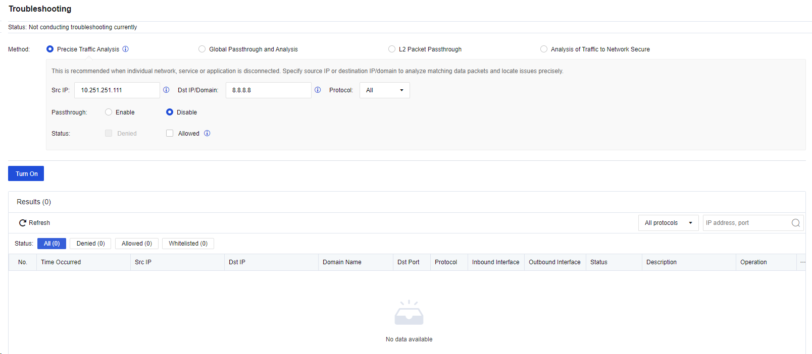
Precise Traffic Analysis: We recommend that you select this method when some users cannot access the Internet or some services/applications cannot be used. You must enter the source IP address or destination IP address/domain name for directional analysis to rapidly locate fault causes. This method is recommended for troubleshooting.
Global Passthrough and Analysis: We recommend selecting this method if large-area networks that cannot be directionally analyzed are interrupted, such as the network environment for device installation. Proceed with caution.
L2 Packet Passthrough: We recommend that you select this method if the fault causes still cannot be located by using the preceding two methods. Proceed with caution.
Analysis of Traffic to Network Secure: It is recommended to use this function when the access to the NSF is abnormal.
If you select one of the four methods, specific policy matching records for the Network Secure device will be displayed in an analysis result list. You can click View Details to view the packet analysis details, to find out which module of the device intercepts the user data, as shown in the following figure.

To globally block or release an IP address, go to SOC > Blacklist/Whitelist, and select Whitelist or Blacklist to add the IP address to be allowed or blocked.
Web Command Console
Web Console allows you to configure and view device settings using command lines on a web page. After you select the Web UI as Management Method for the admin on the System > Administrator page, you can use Web Console in the same way as using a CLI via SSH. For more information about the command lines, refer to the command-line manual.
Packet Capture Tool
Advanced capturing of packets is to capture packets by running the tcpdump command and storing the captured packets in the console interface of the device. You must install the packet capturing software, such as Wireshark or Sniffer, on the computer to open the packets for analysis. In advanced capturing mode, you can capture all data transmitted through the device’s NIC.
Navigate to System > Troubleshooting > Tools > Packet Capture and click Create Capture Task and select either Non-rolling or Rolling. In the Settings dialog box, set the number of packets captured and port, and set packet capture conditions, as shown in the following figure.
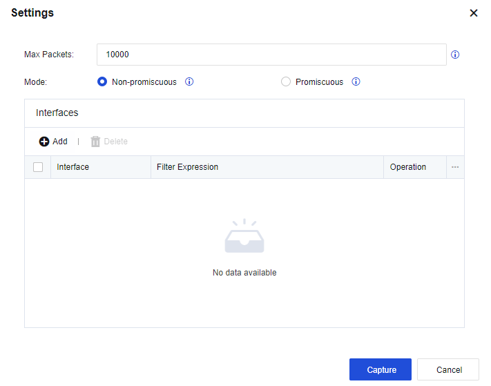
The Filter Expression is the same as the tcpdump command. If you capture packets at the IP address 192.168.1.100, the filter expression for the packets at port 80 is as follows:
host 192.168.1.100 and port 80
Click Capture. Then, the device starts to capture packets, and the captured packets can be downloaded from the Packet Capture tab.

Troubleshooting
This section mainly introduces part of the common problems encountered during the Network Secure operation and maintenance process and their handling flows. It helps the administrator rapidly handle these problems based on the conditions.
Unable to Log in to the Network Secure Console
-
Check whether the ALARM indicator light on the device panel stays solid red.
-
Check whether the ping command can ping the device’s LAN port successfully.
-
Check whether you can telnet to ports 443 and 51111 of the device from the LAN.
-
Run the tracert command to trace the IP address of the LAN port of the device and check whether packets can reach the LAN port of the Network Secure device.
-
Connect a computer to the Management port (the eth0 port by default) through the network cable, and set the IP address of the computer to the 10.251.251.0/24 network segment. Then, test whether the Management port’s default IP address (10.251.251.251) is accessible.
-
Change the browser to repeat Step 5.
-
If you still fail to log in to the device, contact Sangfor Technical Support in time.
Abnormal Access to the Business System
-
Check whether the business system is normal.
-
Check whether the Network Secure application control policies release the data.
-
Enable the passthrough function of the Network Secure device to test whether the network application is accessible.
-
Sangfor Network Secure device provides the one-click soft bypass function if it works abnormally.
Operation procedure
In System > Troubleshooting > Troubleshooting, select Global Passthrough and Analysis. This will disable all modules with the interception function in the device, and display the data to be intercepted but released in the current state.
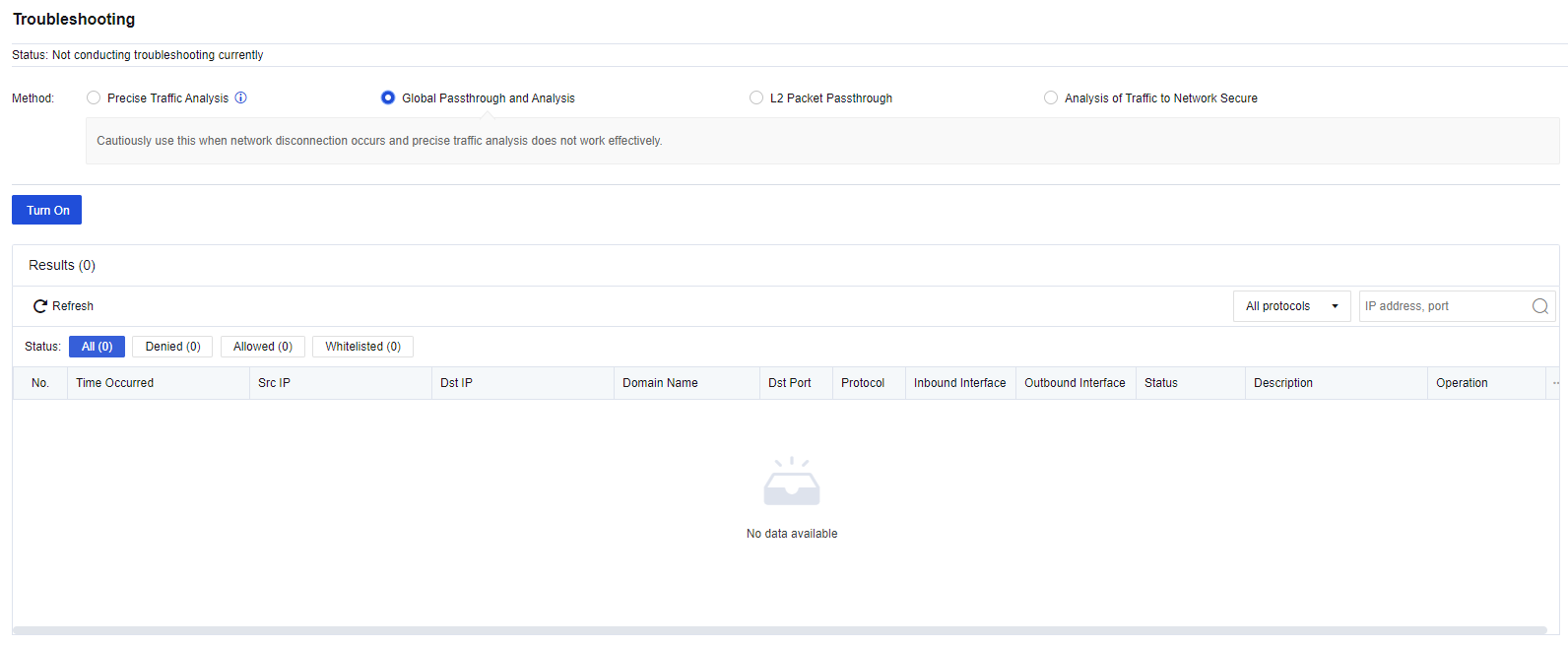
- If you still fail to access the business system, contact Sangfor Technical Support in time.
Device I/O Exception
If the device suffers from heavy traffic, its performance degrades dramatically. The login to the console delays or fails. More seriously, the device is suspended, the access to the Internet is slow, or even interrupted.
Besides abnormalities caused by attacks such as DoS/DDoS, another kind of issues will be easily ignored:
The Network Secure enables the logging function of the application control policy or the traffic audit logs. The disk frequently reads and writes data, causing high usage of the I/O and CPU, and even corruption in the disk. It is strongly recommended to record these logs in the external data center or Syslog server rather than the built-in data center.
The logs of the application control policy are shown as the following figure, in which the Yes in the Logs column means to record logs:
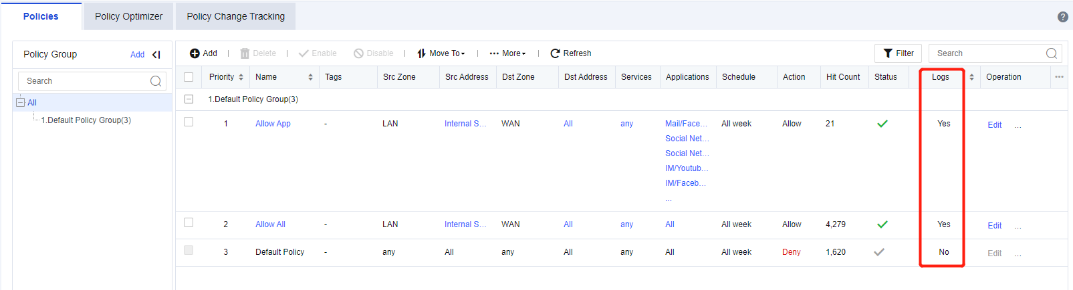
The Traffic Audit Logs is as shown below (Disable it normally). If you need to enable it, select the Syslog (Recommended) or Cyber Command for the logging location. It is not recommended to record logs in the firewall.
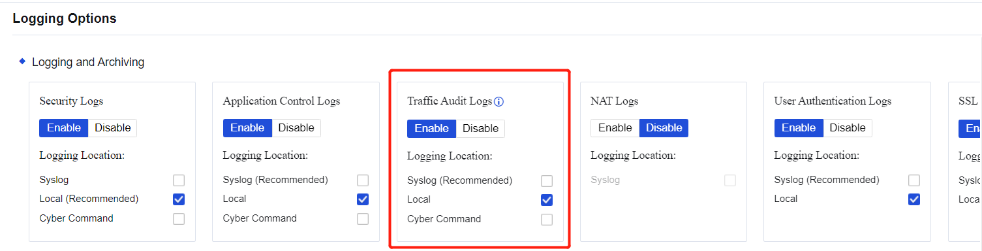
Failing to Update the Rule Database
- In System > Security Capability Update, check whether the expiry date of the rule database update service is up to date.
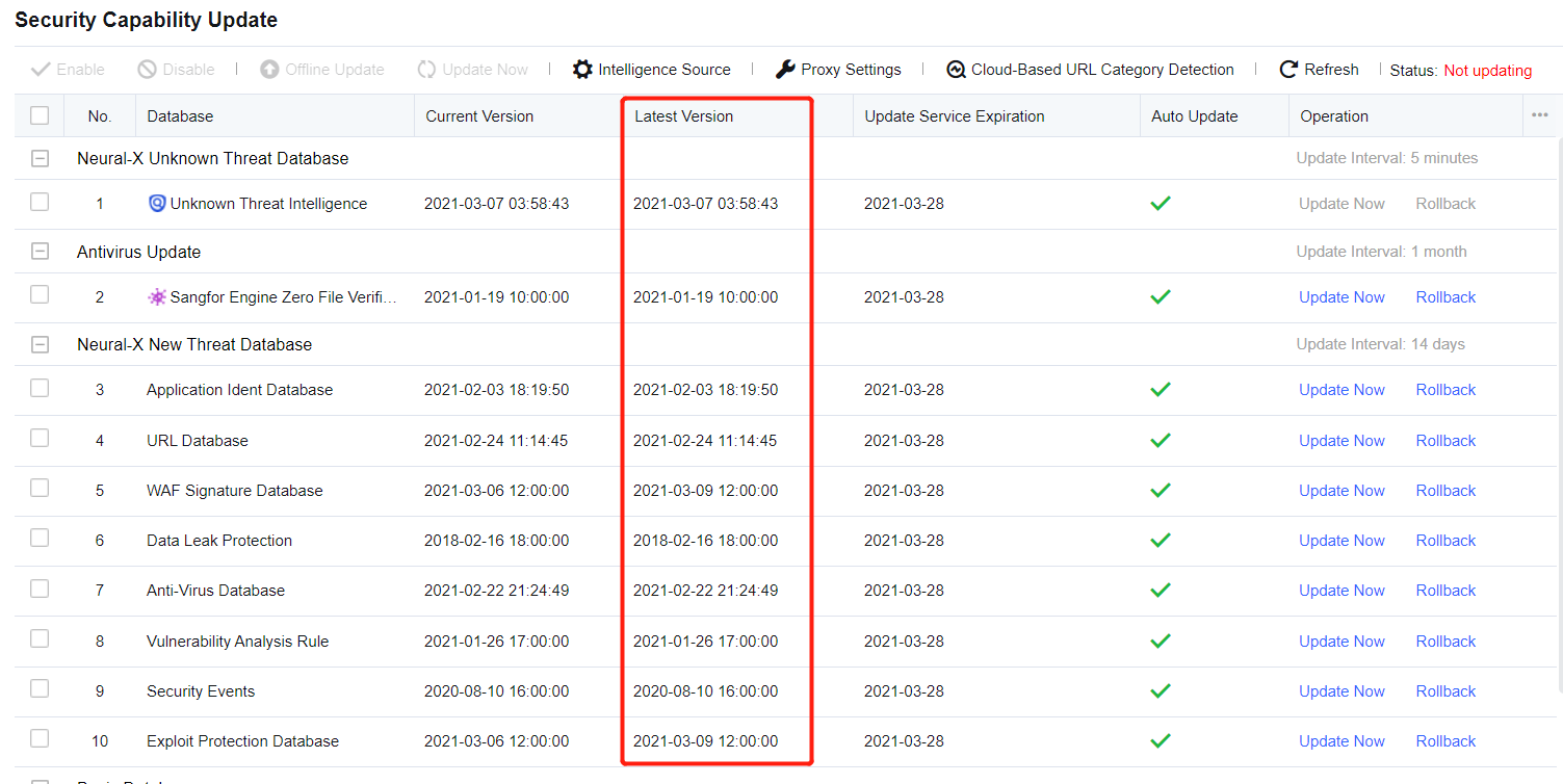
- If the device cannot access the network, download the rule database offline from the official website to update. If no rule database is available on the official website, contact Sangfor Technical Support to update the rule database for you.
Emergency Event Handling
Exception or Network Disconnection of Major Business System
-
Enable Precise Traffic Analysis for this business system to check whether it returns to normal. If so, view the interception logs to find out modules denying inbound and outbound packets, and modify the policy. Disable Precise Traffic Analysis to test whether the service access returns to normal. If not, enable Precise Traffic Analysis again and modify the policy according to the interception logs until failures are repaired.
-
Ping to the Network Secure device from the LAN PC and test whether the PC can access the Network Secure normally. If so, try to ping to the gateway and WAN from the Network Secure using command-line tools, to confirm whether the WAN is available.
-
Enable Global Passthrough and Analysis to check whether the user can access the Internet. If so, view the interception logs to find out modules denying inbound and outbound packets, and modify the policy. Disable Global Passthrough and Analysis to test whether the Internet access returns to normal. If not, enable Global Passthrough and Analysis again and modify the policy according to the interception logs until failures are repaired.
-
Deploy a device in bridge mode and determine whether bridge interfaces are bypass interfaces that are usually marked on the interface panel. If they are not marked, eth0 and eth2 ports are regarded as a pair of bypass interfaces. If the bypass interfaces are used as network bridge interfaces, turn off the device and test again.
-
Turn off the device and check whether the service returns to normal. If the eth0 and eth2 ports are not bypass interfaces, connect the uplink and downlink to a pair of bypass interfaces to check whether the service returns to normal, or directly skip the firewall and test again.
-
If you still fail to troubleshoot, skip the device and test again.
-
After that, if the business system returns to normal, contact Sangfor Technical Support to check whether the device is abnormal.
-
If you still fail to troubleshoot, check whether the configurations of other network devices are abnormal.
Device Hardware Failure
The ALARM Indicator Light Staying Off and the Device Fails to Power On
-
Power off the device and restore the network connection.
-
Confirm the number of switches in the device. Some devices have only one switch, whereas the others are equipped with a hard switch and a soft switch (elastic switch).
-
For a device equipped with only one hard switch, if the device cannot be powered on after you turn on the switch, the ALARM indicator light stays off. In this case, replace the power strip and the power line. If the device still fails to power on, contact Sangfor Technical Support and return the device to the factory for repair.
-
To power on a device equipped with two switches, turn on the hard switch first and then the soft switch (elastic switch). If the device still fails to power on after you turn on the switches in sequence and replace the power strip and power line, contact Sangfor Technical Support and return the device to the factory for repair.
The ALARM Indicator Light Staying On and Failing to Log in to the Device
-
Power off the device and restore the network connection.
-
After 30 minutes, power on the device again and wait for two hours. If the device is powered on normally within two hours, it indicates that the device performed the self-inspection before. If the ALARM indicator light stays on after two hours, contact Sangfor Technical Support and return the device to the factory for repair.
Networking Interface Failure
-
Replace a network cable and check whether the interface can work normally.
-
Change the rate and duplex mode of the failed interface and check whether compatibility issues exist when the networking interface is used.
-
Go to Network > Interfaces > Physical Interfaces and click the interface you want to edit. Click Advanced and select different rates and duplex modes to check whether the interface can work normally.
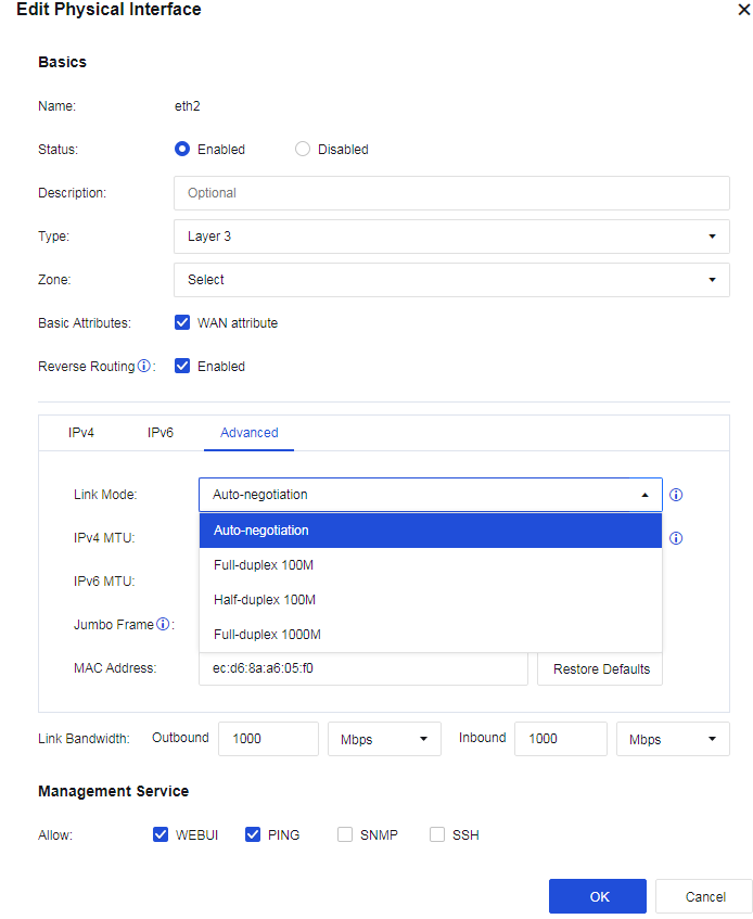
-
Connect the failed interface to other interfaces of a switch or other network devices and check whether the interface can work normally.
-
Disconnect the device from the network. Contact Sangfor Technical Support to confirm whether hardware failures exist. If so, return the device to the factory for repair.
Product Upgrade Guide
The product upgrade guide introduces the specific methods for upgrading the device system and the checks before and after the upgrade.
Product Upgrade Steps
-
For the intranet upgrade scenario, you need to prepare the upgrade package in advance before upgrading to ensure the integrity of the upgrade package.
-
Get the upgrade package download link in https://community.sangfor.com/plugin.php?id=service:download&action=view&fid=10#/1/all and save it to your computer locally.
-
Use the MD5 verification tool to verify the MD5 of the upgrade package to ensure the integrity of the upgrade package.
-
In the online upgrade scenario, you need to ensure that the device’s network is upgraded and that the server is smooth before upgrading. Please check before upgrading the product.
Product Pre-upgrade Inspection
Before upgrading, you need to confirm whether the current version you are using supports a direct upgrade or not. Also, whether the upgrade affects the old features, requires a restart, and the estimated upgrade time.
Besides, you also need to confirm the user configuration, logs, and data are smoothly upgraded and whether the upgrade is limited.
Upgrade through the Web
Web-Based System Upgrade Methods
The web system upgrade includes two methods: online upgrade and offline upgrade.
-
Online upgrade: After entering the System > Maintenance > Upgrade, the device will connect to the Internet to check whether an upgrade package is higher than the current device software version on the upgrade server.
-
If yes, it will upgrade online; if not, it will show The device is up-to-date .
-
For offline upgrade, enter the System > Maintenance > Upgrade, click the Update button, upload the local upgrade package, and follow the instructions to complete the upgrade.
Web-Based System Upgrade Procedures
Offline Upgrade
- Go to System > Maintenance > Upgrade. You can perform firmware upgrade or view Upgrade History.
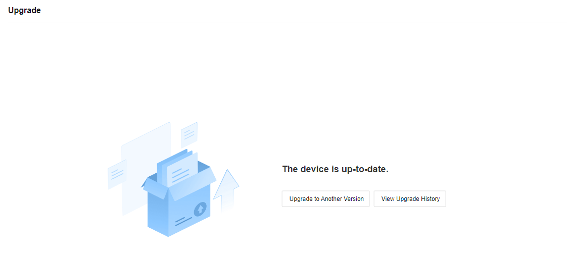
- Click the Upgrade to Another Version button and you will move to the Get Files Ready section.
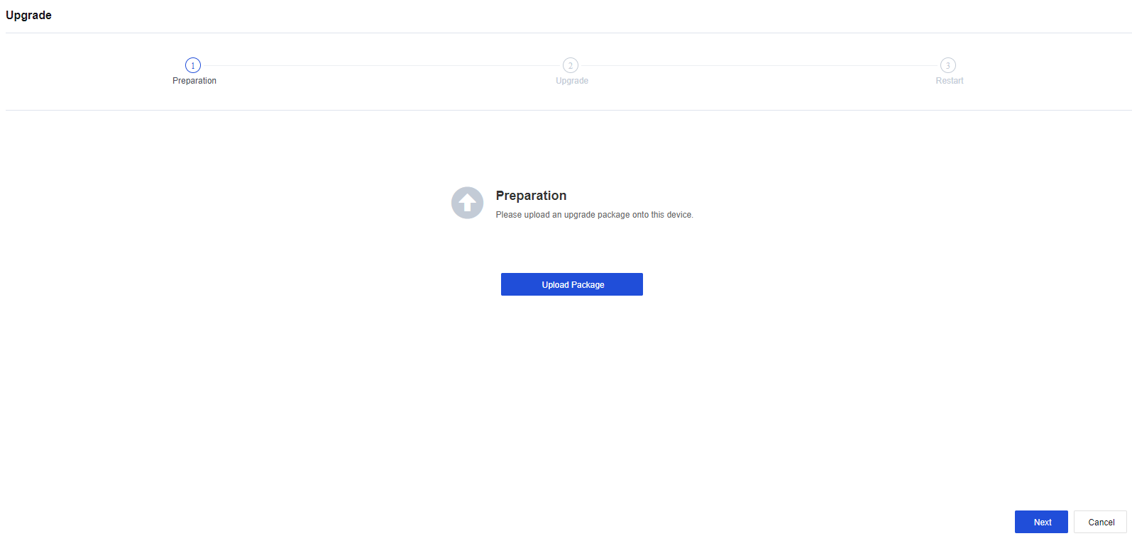
- Click the Upload Package button to upload the upgrade package from the local PC.
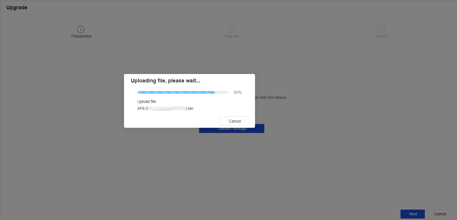
- After the upgrade package is uploaded, click Next to complete the configuration backup to start the upgrade. After the upgrade is completed, the device will reboot automatically. After the reboot is completed, log in to the device console and check the status of the device.
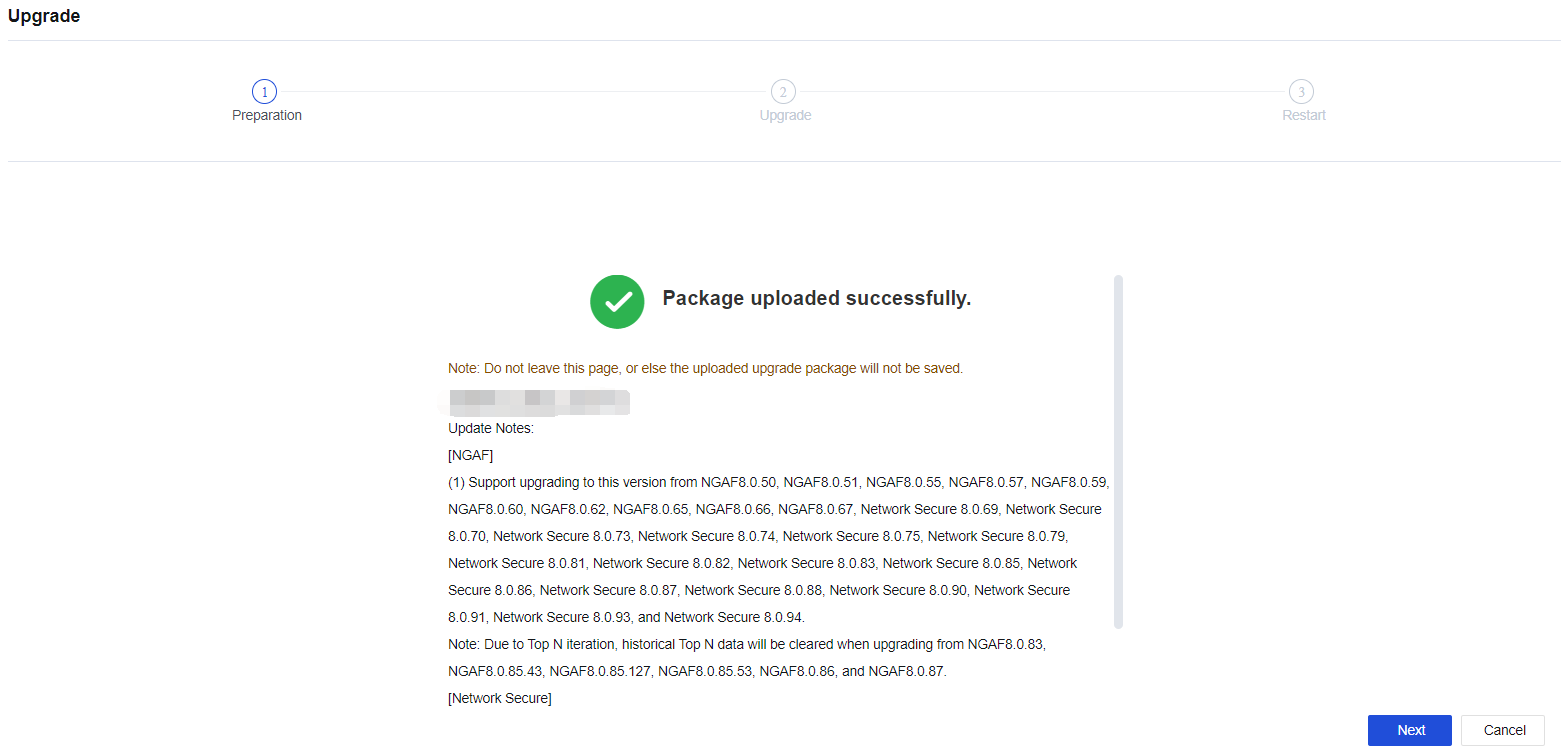
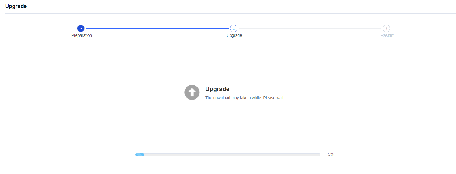
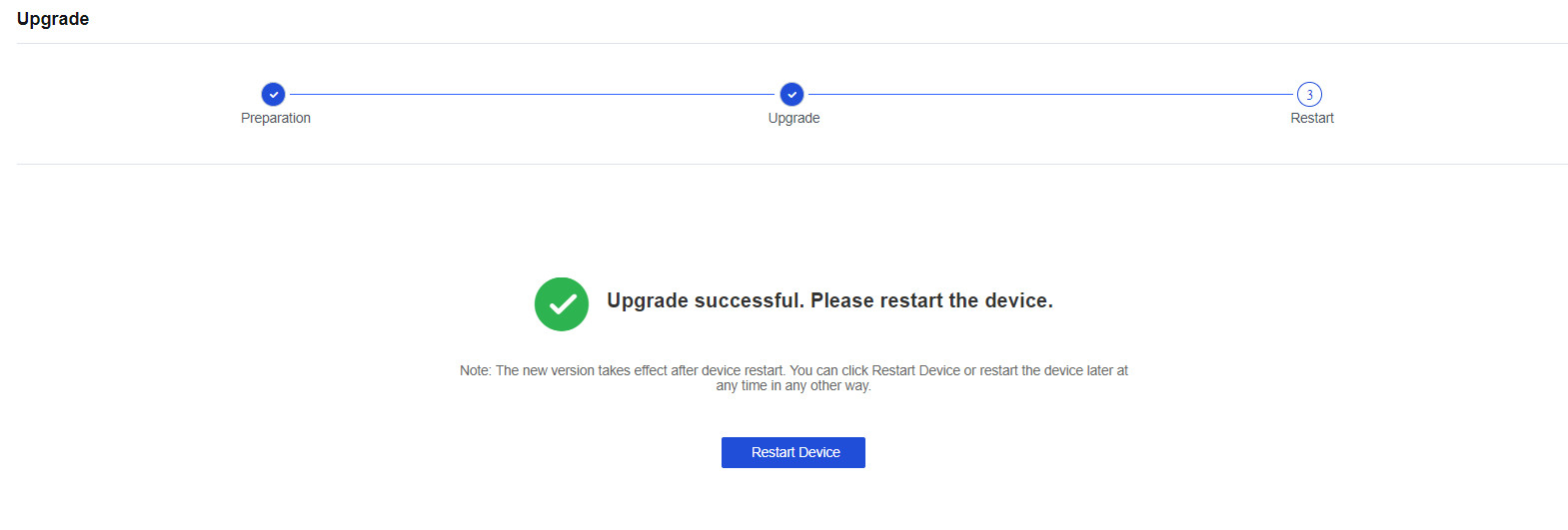
Notice:
During the uploading, backup, or upgrade process, you cannot close the page. Otherwise, you need to re-enter the page and perform the upgrade operation again.
Upgrade Through Central Manager
Central Manager-based upgrade is used for upgrading Network Secure devices managed on Central Manager. It allows you to upgrade multi-branch Network Secure devices in bulk.
Central Manager-Based Upgrade Steps
-
Log in to the Central Manager console and click System > Upgrade > Branch Device Upgrade.
-
Add a scheduled upgrade task and complete the configurations.
-
The Central Manager automatically distributes the upgrade task to branch Network Secure devices at the scheduled time.
Central Manager-Based Upgrade Procedures
- Log in to the Central Manager console as the administrator. Go to System > Upgrade > Branch Device Upgrade, click Add Scheduled Upgrade Task and complete the configurations.
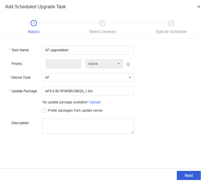
Notice:
- If no update package is available on the Central Manager console, click Upload to upload the required package.
- A branch device can obtain the update package by communicating with Central Manager or downloading the package from the update server (when Prefer packages from update servers is checked).
- Click Next and select devices to be upgraded and define the bulk upgrade scope.
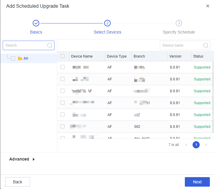
- Click Next and configure a scheduled upgrade task.
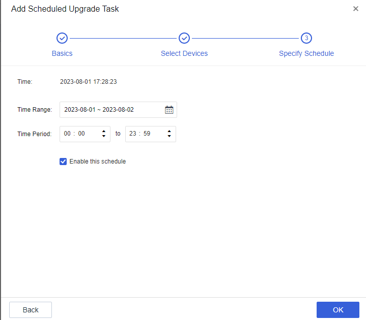
- The upgrade task will be automatically triggered at the scheduled time.
Product Post-Upgrade Inspection
Network Connectivity
| No. | Item | Requirement |
|---|---|---|
| 1 | Whether the endpoint can access the Internet. | The endpoint can access the Internet when the device is online. |
| 2 | Whether the server can access the specified external address. | The server can access the specified external address when the device is online. |
| 3 | Whether the external service published by the server is accessible. | The external service published by the server is accessible when the device is online. |
| 4 | Whether the switchover solution provided in the POC manual works properly (an HA environment is required). | The switchover solution provided in the POC manual works as expected. |
| 5 | Whether the administrator can access Network Secure through the management IP address. | The administrator can access the Network Secure console remotely and perform operations on the console as expected. |
| 6 | Whether the device can connect to the Internet. | The device is connected to the Internet for updating the database and service packs. |
Device Health
| No. | Item | Requirement |
|---|---|---|
| 1 | Whether the device CPU usage is normal. | Under normal conditions, the average CPU usage does not exceed 70%. |
| 2 | Whether the device memory usage is normal. | Under normal conditions, the average memory usage does not exceed 70%. |
| 3 | Whether error logs or alert logs exist in system logs. | Under normal conditions, no error logs or alert logs exist in system logs. For any exceptions, contact the vendor. |
| 4 | Whether remote maintenance over the WAN is disabled. | For security reasons, remote maintenance over the WAN is disabled after the implementation is complete. |
| 5 | Whether the device configurations are backed up. | The device configurations are backed up and archived locally after implementation. |
| 6 | Whether the database is up-to-date. | The database is up-to-date after the implementation is complete for optimal application identification accuracy. |
| 7 | Whether network logs in the data center are configured to be retained for no less than six months in accordance with the Cybersecurity Law. | After the implementation, the expected retention period for using Network Secure or external syslog is at least 180 days. |
Acronym
| Acronym | Full Name |
|---|---|
| SNMP | Simple Network Management Protocol |
| RADIUS | Remote Authentication Dial In User Service |
| DNS | Domain Name System |
| LDAP | Lightweight Directory Access Protocol |
| DHCP | Dynamic Host Configuration Protocol |
| ARP | Address Resolution Protocol |
| TCP | Transmission Control Protocol |
| UDP | User Datagram Protocol |
| VLAN | Virtual Local Area Network |
| NAT | Network Address Translation |
| NetBIOS | Network Basic Input/Output System |
| CM | Central Manager |
| IM | Instant Messaging |
| ES | Endpoint Secure |
| AD | Active Directory |
| VPN | Virtual Private Network |