【SCP】Disaster Recovery Configuration Guide_V6.7.30
Introduction
The disaster data center is part of the business reliability technology. The disaster recovery solution mechanism is to increase business data reliability by performing health monitoring for its data center and production data between the two data centers. When the data center unplanned fault occurs, it allows a quickly recover of business in the center of the disaster database so that the business system can continue to work normally.
Two indicators of a service failure recovery goal:
- Time required to recover
- How long data was lost before the failure.
Recovery Time Objective (RTO): The maximum allowable duration for a computer, system, network, or application to stop working after a fault or disaster occurs.
Recovery Point Object (RPO): The point in time at which data can be recovered in the event of a disaster or emergency. It is the amount of data loss that the serving system can tolerate.
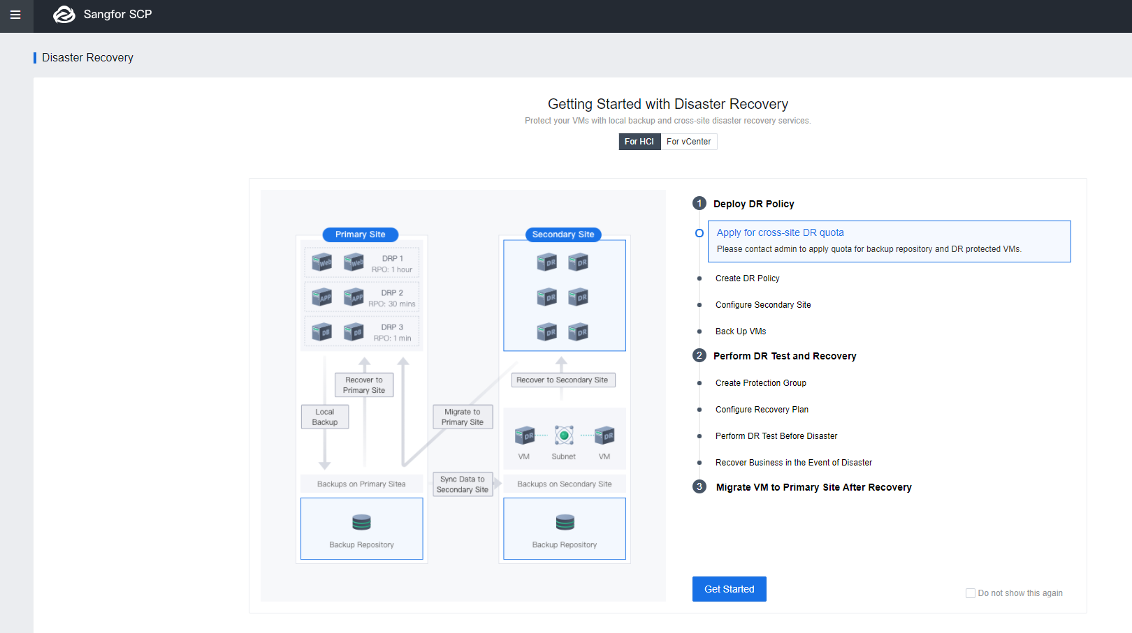
The following figure shows the Disaster Recovery (DR) Configuration process.
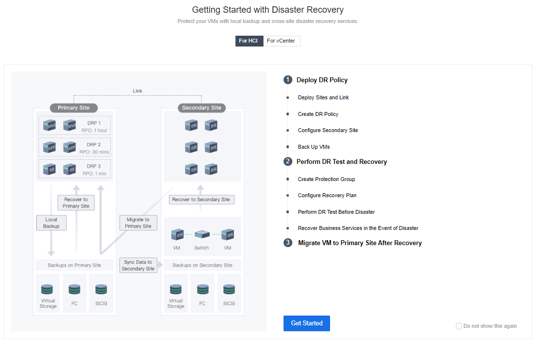
Deploy DR Policy
Deploy Sites and Link
Layer 2 Link
The DR link synchronously transmits data. In this solution, the primary and standby data centers use the management interfaces as DR interfaces linked through a layer-2 link. IPs of both centers are in the same segment, so that they can ping each other.
-
Access to SCP platform, and navigate to Resources > Reliability > Disaster Recovery. Click Get started.
-
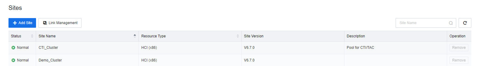
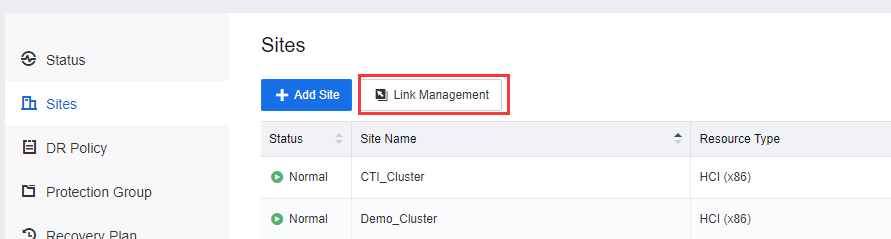
Select Sites and click Add Site to add the Primary and Secondary sites.


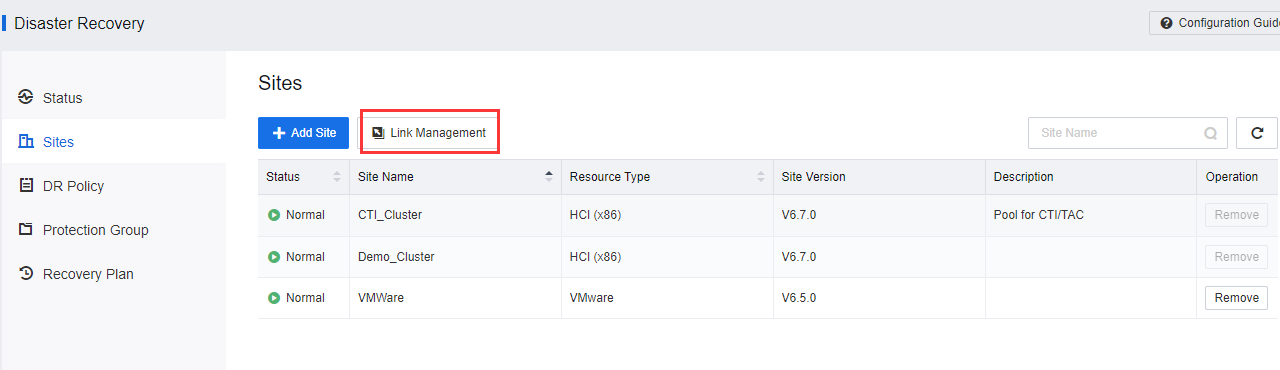
- After the Primary and Secondary sites have been added, click Link Management.

- Click New Link to configure the DR interface between the Primary and Secondary sites.

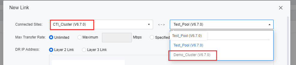
- On the New Link page, select the primary and secondary sites under Connected Sites.
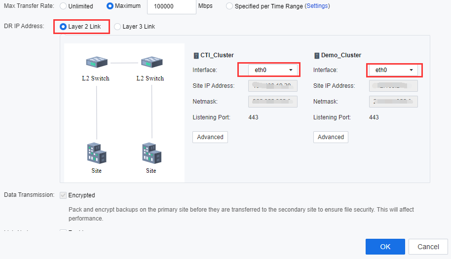
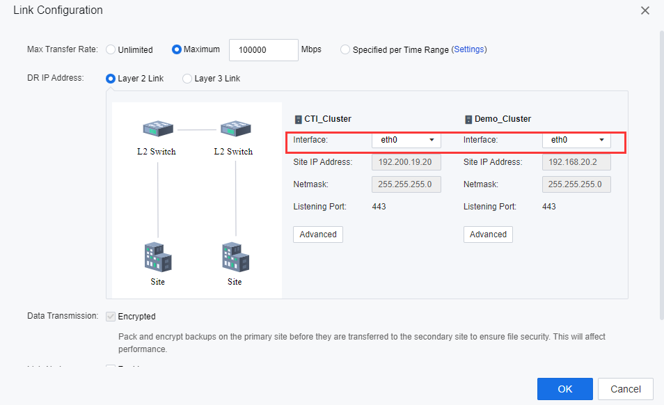
- Select Layer 2 Link for DR IP Address. Select Communication Interface at the selected primary and secondary sites. The management interface is optional. When sufficient interfaces are available, and DR Traffic is heavy, users are advised to configure an independent DR incoming interface.
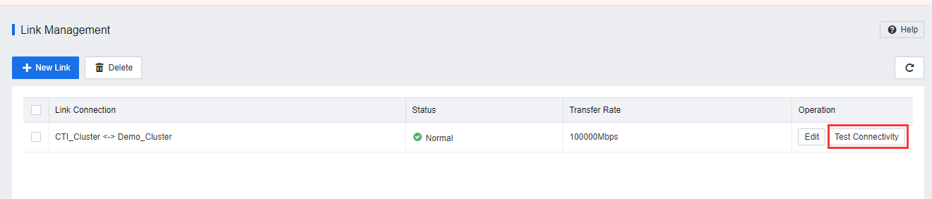
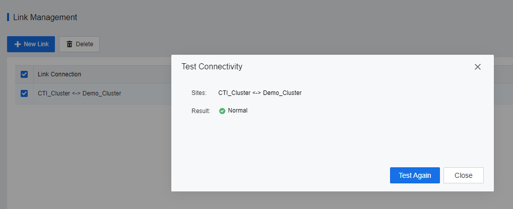
- After the sites and links are configured, the entity will be shown on Resource > Disaster Recovery > Sites > Link Management.

- By clicking on Test Connectivity, the user will be able to check the connection status between the DC cluster and DR cluster.
Layer 3 Link
The DR link synchronously transmits data. In this solution, the primary and secondary data centers use the management interfaces as DR interfaces linked through a layer 3 link. It allows the primary and secondary sites to communicate even when the IPs of the centers are in the different segments and cannot link to the public network directly. Furthermore, the layer 3 link supported the communication between cluster sites through NAT.
-
Access to SCP platform, and navigate to Resources > Reliability > Disaster Recovery. Click Get started.
-
Select Sites and click Add Site to add the Primary and Secondary sites.

- After the Primary and Secondary sites have been added, click Link Management.
- Click New Link to configure the DR interface between the Primary and Secondary sites.

- On the New Link page, select the primary and secondary sites under Connected Sites.

-
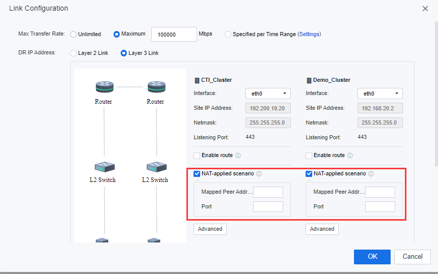
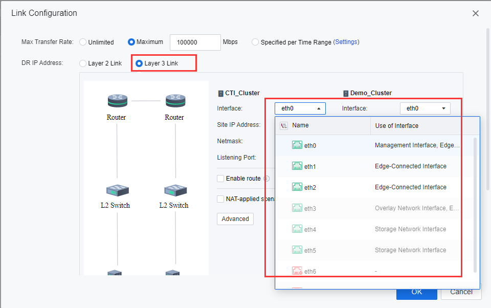
Select Layer 3 Link for DR IP Address. Select Communication Interface at the selected primary and secondary sites. The management interface is optional. When sufficient interfaces are available, and DR Traffic is heavy, users are advised to configure an independent DR incoming interface.
-
After selecting the interfaces, check the Enable route checkbox, and configure the Next-Hop IP for both sites. Specify the next-hop IP address when there is any router between the primary and secondary sites.
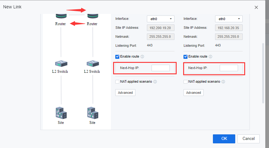
- After selecting the interfaces, check the NAT-applied scenario checkbox, and configure the NAT by specifying the translated peer site IP address on Mapped Peer Address and Port for both sites.
- After the sites and links are configured, the entity will be shown on Resource > Disaster Recovery > Sites > Link Management.
- By clicking on Test Connectivity, the user will be able to check the connection status between the DC cluster and DR cluster.
Reuse Interface
- Select either Layer 2 Link or Layer 3 Link for DR IP Address based on the actual environment. Select the Interface for the selected primary and secondary sites. Alternatively, reuse the management network interface. On the Interface module, select the Management Interface for each node as the DR Data Transmission Interface.
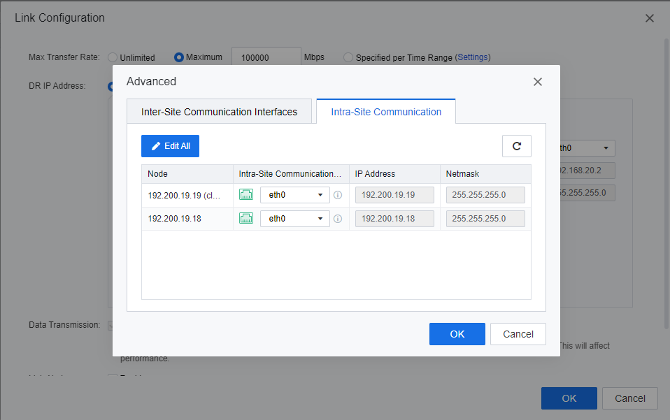
- Click Advanced on the Intra-Site Communication page, and select the management interface for each node as the Intra-Site Communication interface. The DR interface is used to transmit DR Data to the cluster controller. Keep the default DR interface.
- Click OK to complete the link configuration.
Independent Interface Deployment (Optional)
-
Select either Layer 2 Link or Layer 3 Link for DR IP Address based on the actual environment. Then, select the Interface for the selected primary and secondary sites.
-
Select the planned DR network interface at each site as the Site IP Address. (If the DR network interface is aggregated, configure the aggregation on the network interface configuration page of the hyper-converged physical machine in advance.)
-
Fill in Site IP Address and Netmask according to the IP plan table, then click Advanced, as shown in the following figure.
-
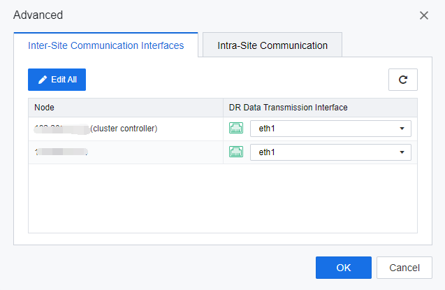
On the Advanced > Inter-Site Communication Interfaces tab, select an interface for each node based on the IP plan table.
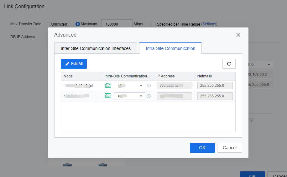
- On the Advanced page, click the Intra-Site Communication tab and select Intra-Site Communication Interface, IP address, and Netmask for each node according to the IP plan table. Then, click OK to add the link.
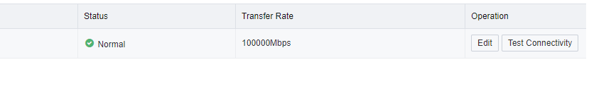
- The configured links will be displayed on the Link Management page. Ensure that Connection Status is Normal. Then, click Test Connectivity to test the link status.
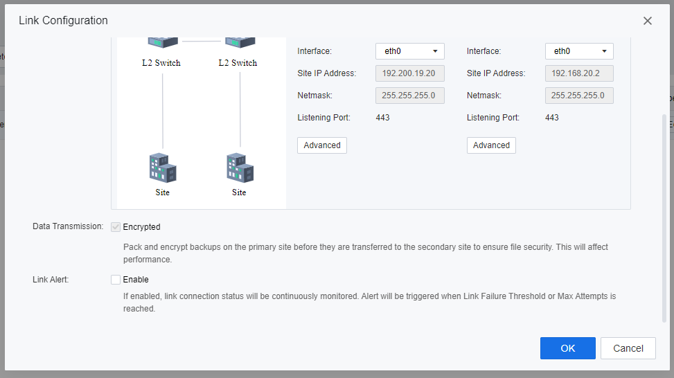
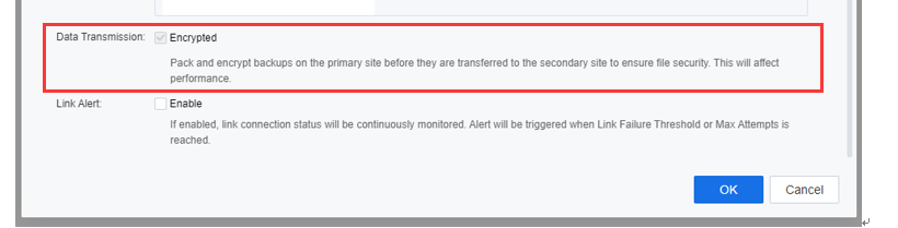
- On the bottom of the Link Configuration page, check the Encrypted checkbox beside Data Transmission if the user needs to ensure the transmission and file security are packed and encrypted on the primary site before being transferred to the secondary site. However, be aware that data transmission performance will be affected if the Encrypted is enabled.
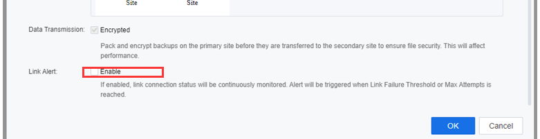
- Check the Enable checkbox beside Link Alert if the user needs to continuously monitor the link connection status. After enabling Link Alert, link connection status will be continuously monitored, and an alert will be triggered when Link Failure Threshold or Max Attempts is reached.
Note:
SCP allows reusing the HCI management network as the Disaster recovery interface. If the DR traffic is heavy, users are advised to configure an independent interface for Disaster Recovery.
The DR IP Address selection was based on the actual environment deployed on user sites. Layer 3 link was usually configured when NAT environment and Inter-Site connection existed. Meanwhile, the Layer 2 link was when both clusters locate within the same segment.
Intra-site communication refers to the connection between HCI nodes within the cluster, whereas Inter-site connection refers to the connection between clusters.
Layer 3 link are usually used when the DR Interface is planned independently. Therefore, enter the next-hop route and do not set an independent gateway for the network adapter to avoid gateway conflicts.
After the DR Policy is deployed, if DR Link is normal, but access delays exist, or unable to meet the RPO. Please verify whether the SCP and the HCI platforms are located at the two different places and whether the network between the HCI platforms at the two places supports large packets (-S 3000) transmission.
Create DR Policy
Users are able to set DR Policies for VMs and configure parameters such as backup schedule and transmission frequency, which can be used for WEB systems and applications.
DR Policies are configured for VMs with different RPO requirements, such as systems and databases, to meet hierarchical data protection requirements demand.
- Navigate to Resources > Reliability > Disaster Recovery. Click Get started.

- Navigate to DR Policy > New, and configure DR Policy as below:
a) Configure a Name for the DR Policy.
b) Select the Primary Site.
c) Select the Secondary Site.
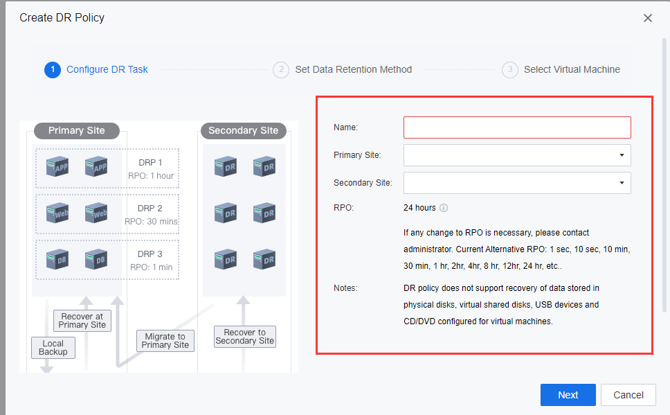
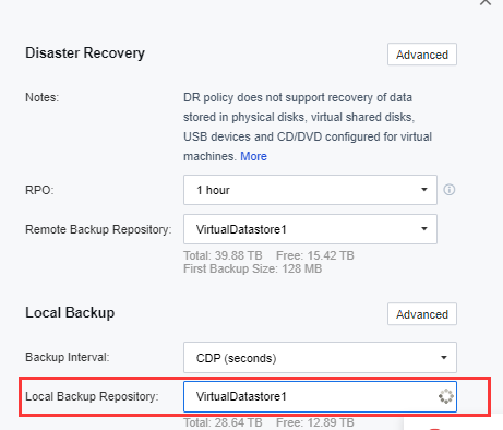
d) Set the Disaster Recovery RPO. The RPO refers to the acceptable amount of data loss when an application goes down. The more important the data is, the smaller the RPO value should be. A smaller RPO value means that backup and data sync is performed more often, but pressure on the production environment and network is also higher.
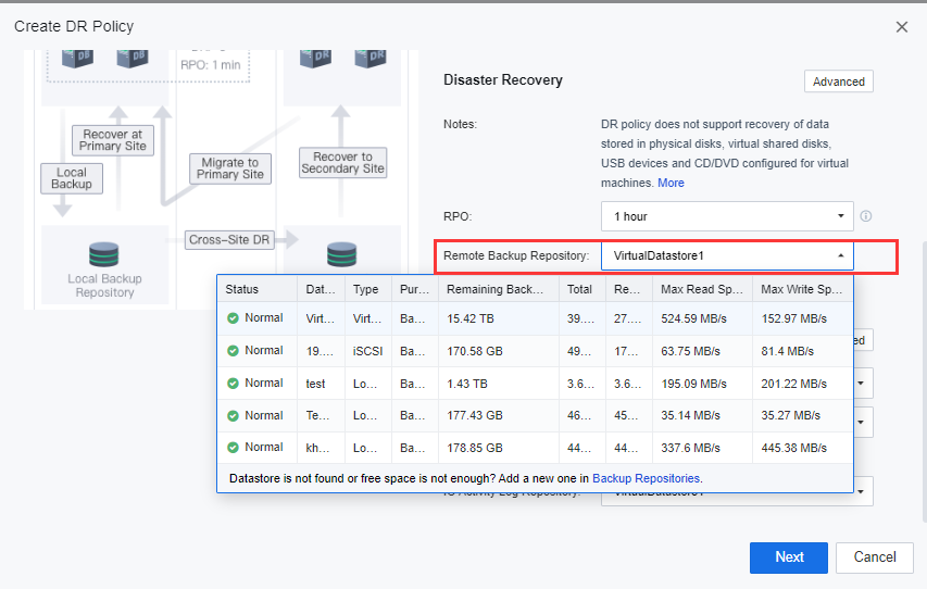
e) Configure the Remote Backup Repository, usually the backup repository at the DR Site. It uses as the location to transmit and store the placeholder backup data.
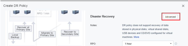
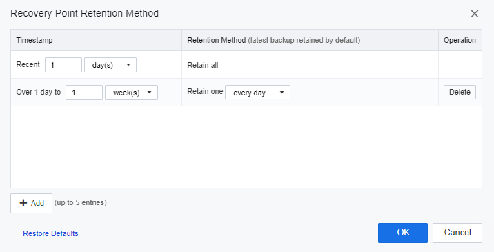
f) On Disaster Recovery, click Advanced and then click Recovery Point Retention Method to configure the remote retention period.
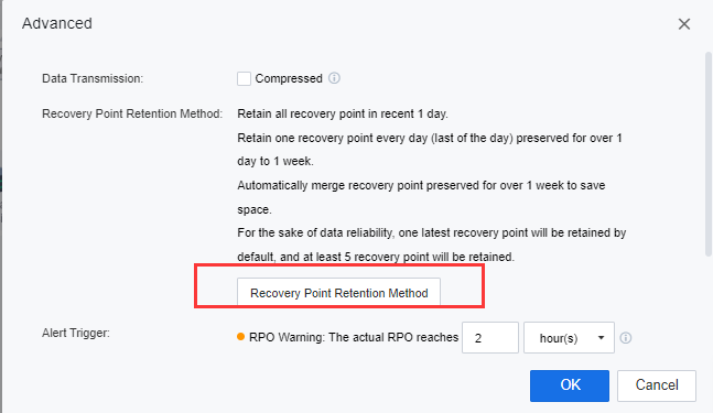
g) In this session, the user is allowed to configure the VMs’ backup file retention period on the secondary site. If the user did not configure this section for data reliability, one latest recovery point would be retained by default, and at least 5 recovery points will be retained.
h) Configure the Local Backup. The local backup frequency must be less than the configured DR RPO. Only Continuous Data Protection (CDP of the second level) is available when the DR RPO is less than or equal to 1 hour.
i) Configure the local backup repository of the primary site. It will be used as the backup repository of the primary site’s VMs’ local backup repository.
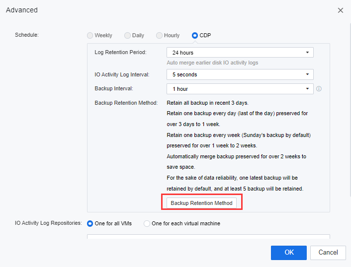
j) On the Local Backup, click Advanced. Users can configure the Log Retention Period, IO Activity Log Interval, and the Backup Interval for the VMs on the primary site.
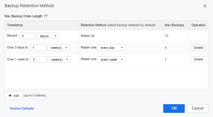
k) Click Backup Retention Method to configure the remote retention period. The user is allowed to configure the VMs’ backup file retention period for the primary site. If the user did not configure this section for data reliability, one latest recovery point would be retained by default, and at least 5 recovery points will be retained.
l) When the local backup mode is CDP, the user needs to select a repository location for I/O log files.
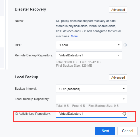
m) Users are advised to select secondary storage and allow a virtual repository.
n) Select a protected VM- a VM that requires DR.
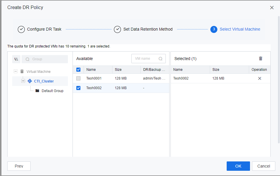


- Click Next to review the configured DR Policy settings. You may check the Execute this policy when policy creation is complete checkbox if you require the DR policy to take effect immediately.
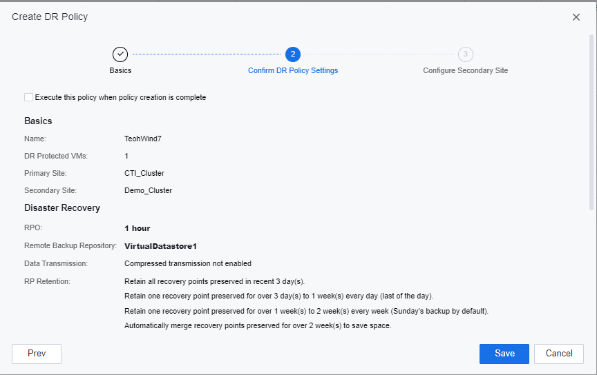
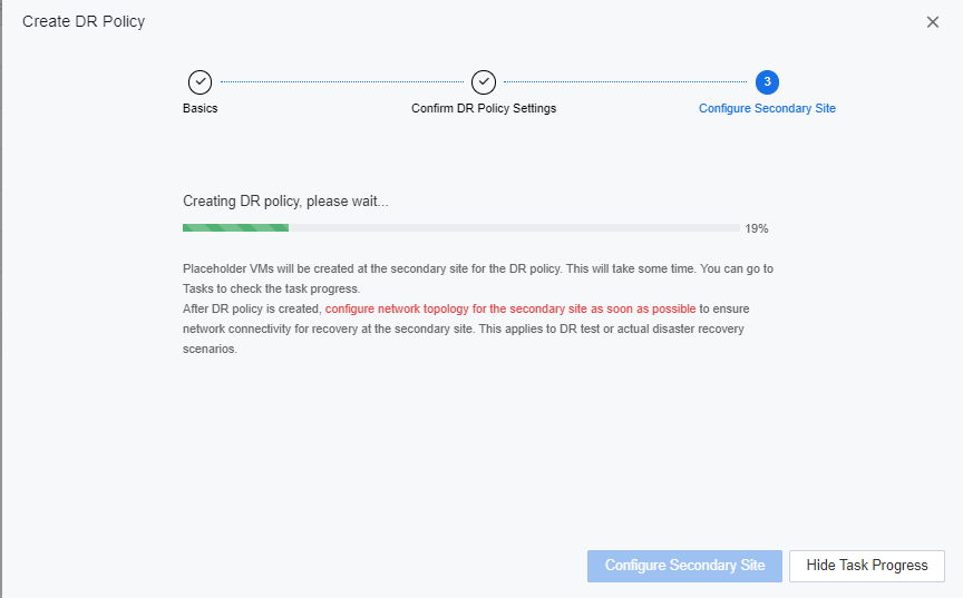
- Click Save to proceed to Configure Secondary Site page. SCP will start to create a DR policy on the secondary site. The user can either configure the Secondary Site or close the prompted windows and configure later.
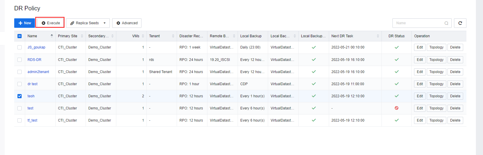
- Create different DR Policies for different VM based on the required RPO. After DR Policies are configured, select a DR Policy and click Execute to initiate the first data backup and DR Transmission. After the configuration is complete, click
 to enable or disable the DR policy.
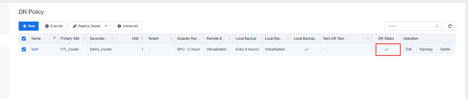
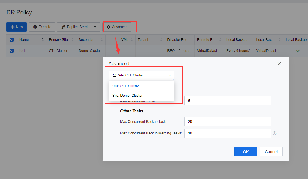
- Click Advanced to configure the DR policy for different resource pools. The number of Max Concurrent Tasks is the primary site number of concurrent backup tasks transmitted to the secondary site. The number of Max Concurrent Backup Tasks indicates the number of VMs backup jobs at a site. Max Concurrent Backup Merging Tasks refers to the number of concurrent backup merge tasks triggered by multiple VMs.
Note:
- Add and configure the storage to the repository before selecting remote and local backup repositories.
- DR remote backup repository cannot add using NFS as it will require creating a placeholder VM.
- Do not use file storage to save IO log files of the CDP.
- The I/O log files and DR Data at the secondary site are stored in the same storage.
- Backup pools at the primary and secondary sites have been planned and configured.
- Make sure the DR Site and DR Link have been configured.
Caution:
If the DC(primary site) VM is powered on by UEFI, when configuring the secondary site, it will require to DR HCI cluster to edit the VM and change the BIOS from SeaBIOS to UEFI.
RPO Alert
RPO is a point in time when data can be recovered when a disaster or emergency occurs. It is the amount of data loss that a service system can tolerate. RPO alert is a mechanism that alerts users that a specified Recovery Point Objective (RPO) of a VM has been exceeded. Hence, the user will be notified and acknowledge the abnormalities and proceed with the VM data transmission troubleshooting between the primary and secondary site to ensure the reliability of the Disaster Recovery solution.
- Navigate to Resources > Reliability > Disaster Recovery. Click Get started.
-
Navigate to DR Policy > New. On the Create DR Policy page, click Advanced beside Disaster Recovery.
-
At the bottom of the Advanced windows, users are allowed to configure the RPO alert as followings:
a) RPO Warning: RPO warning will be triggered and notify the user when the RPO is slightly greater than the configured RPO. The purpose of RPO warnings is to notify users that there may have some issue with the VM data transmission and need to be acknowledged by the user.
b) RPO Alert: RPO Alert will be triggered and notify the user when the RPO hits the configured RPO time interval or if there have 3 RPO warnings triggered. The purpose of the RPO alert is to notify the user that the VM data transmission RPO was in a critical situation. Immediate handling is required.

Configure Secondary Site
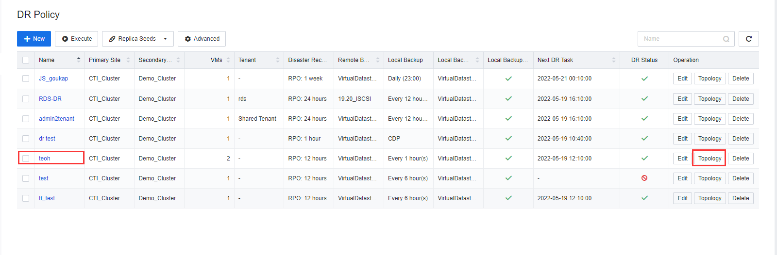
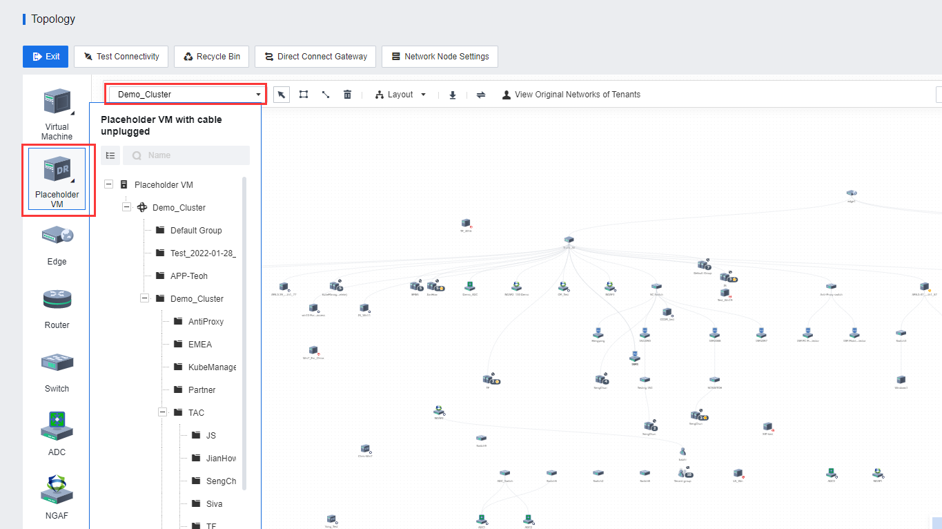
- After the DR Policy is created, click Topology to go to the Network Topology.
- Configure the network at the secondary site and connect the placeholder VMs at the DR Site to the DR Network.
- Configure other DR Policies to enable DR Services on all VMs that require Dr.
Back Up VMs
Initiating the DR Policy will require initializing a full backup transmission. There are two selections to perform the full backup transmission: Execute or Replica Seeds.
- If the user wants to use network transmission for the full backup transmission, click Execute on the respective DR policy to start the full backup transmission.
- If the user is required to replica the seed file for the DR initialization, disable the DR Policy as soon as possible and perform the seed file transmission afterward. See the introduction to the seed file in the next section for details.
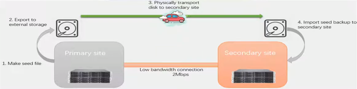
Replica Seeds
After a new DR Policy is created, the full backup of the protected VMs must be copied to the DR Site during replication initiation. If the bandwidth of the DR Network between the primary and secondary sites is low, asynchronous replication may consume a long time. Therefore, seed file transmission was introduced to perform the replication. The User is allowed to export full backup data of VMs to the external disks (such as mobile disks, mechanical disks, and low-capacity NAS) and transport the data to the DR Site to import the data to the DR Site to complete the initialization of VMs. No full backup needs to be transmitted for subsequent data synchronization, but only the incremental data based on the file.
-
Insert the mobile disk into the USB interface of the node of the primary site. This case is written by the mobile disk.
-
Disk mounting ways:
a) Can use USB interface for removable hard disk.
b) Can use disk slot for the physical disk.
c) Use network paths to access external storage (such as external mobile NAS).
-
Mount a mobile disk to the node and log in to the HCI platform of the primary site.
-
After the USB device is inserted, HCI will identify and prompt to configure the USB. Since the disk is not for VMs, there is no need to configure it here. Just close the prompt. If local storage is not identified, please click Rediscover Hard Disk.
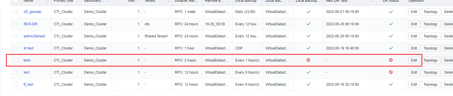
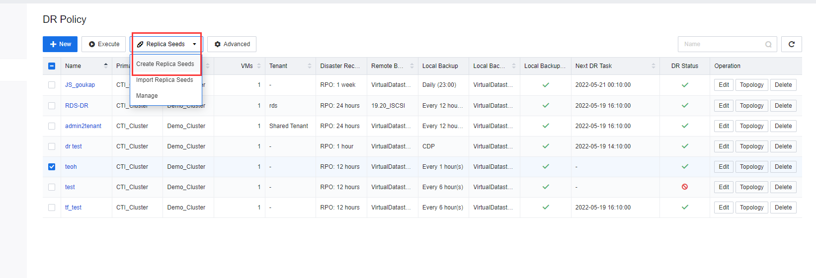
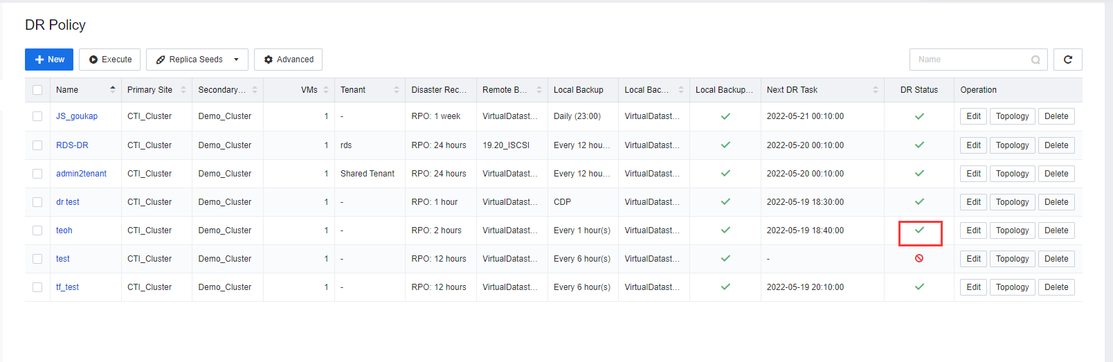
- Log in to the SCP, select DR Policy on the DR Policy page, select the created DR Policy, and click the
 under DR Status To disable DR status. While using the seed file transmission method, the policy must be disabled when the DR Policy is configured.
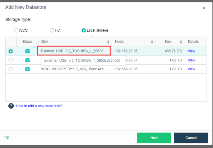
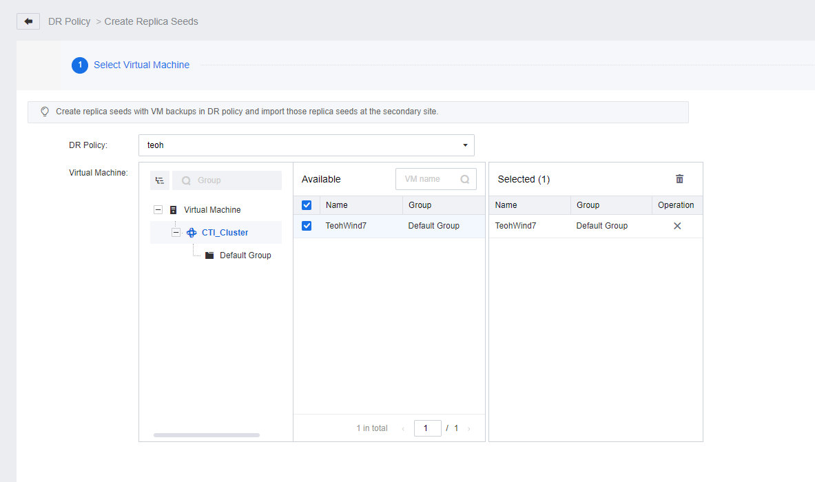
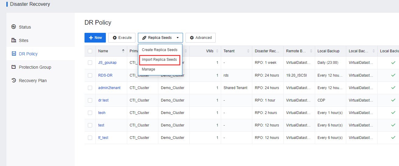
- On the DR Policy page, click Replica Seeds and select Create Replica Seeds. On the Create Replica Seeds page, select the respective DR Policy, the Protected VMs to which the seed file is to be exported, and the datastore location to which the seed file is to be exported.
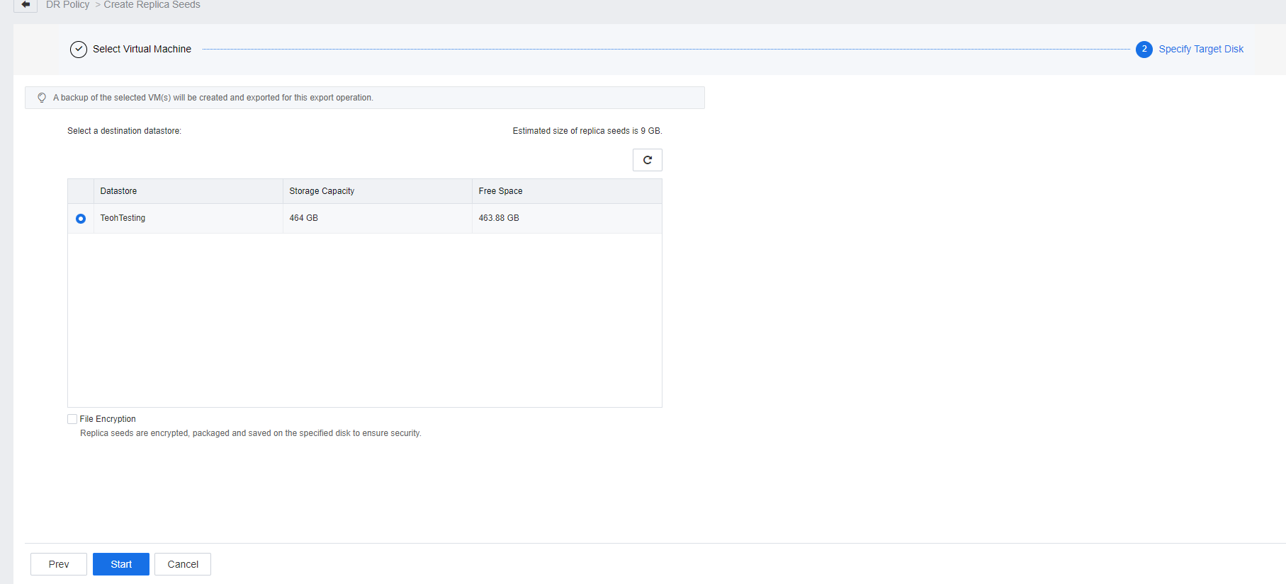
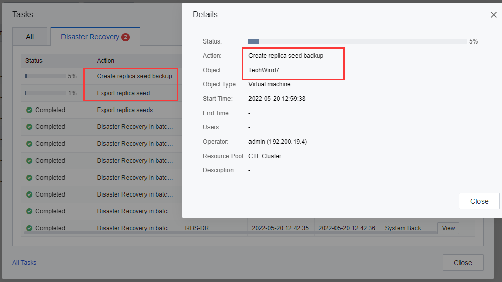
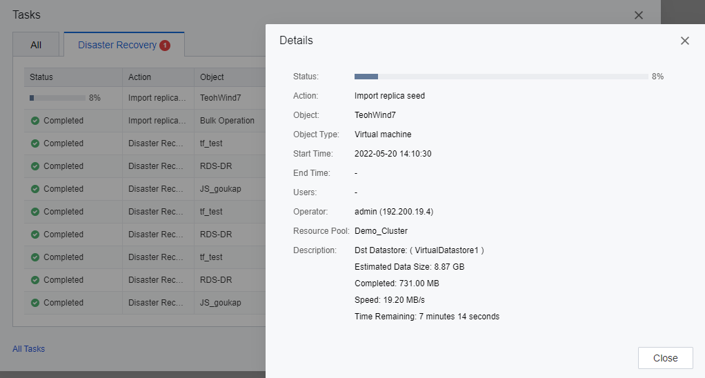
- In the task list, the task progress and details will be shown and allow the user to check whether the backup type is a full backup and whether the size meets expectations (the size of the full backup is close to the actual size of the disk on the VMs). Based on the export process, the user is able to evaluate the export time based on the task details.
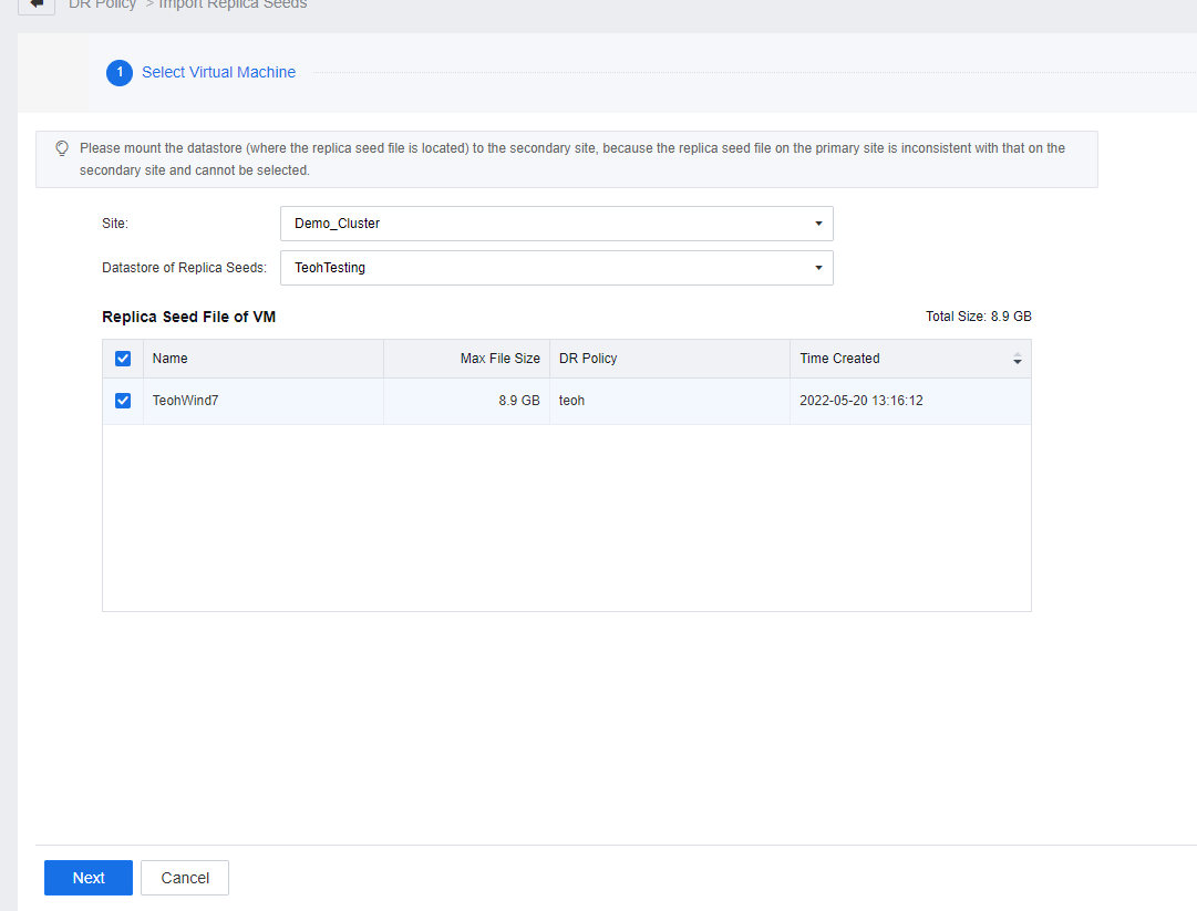
- Delete the datastore that stores the seed files from the HCI of the primary site and transport the datastore to the DR Site. The same mobile disk is mounted to a cluster at the DR Site in the same way as the primary site. Import Replica Seeds.
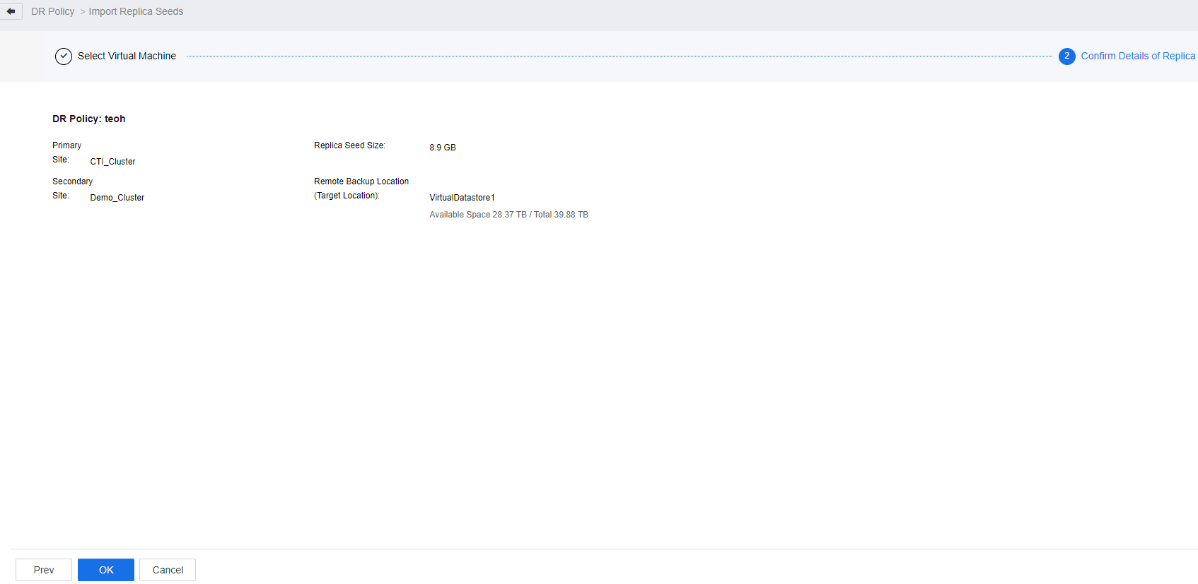
- Select the site where the seed file is located (select the secondary site) and the datastore where the seed file is located. The seed file of the protected VM in the datastore is listed.
- If the seed file fails the import task, check whether the placeholder VM backup exists at the secondary site. If some backup data exists at the secondary site, manually delete the placeholder VM backup and import the seed file again.
- During the Import replica seed process, the task progress will be shown in the task list.
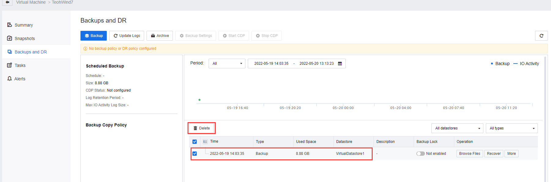
- After the Import replica seed task is complete, an initial backup will be generated.
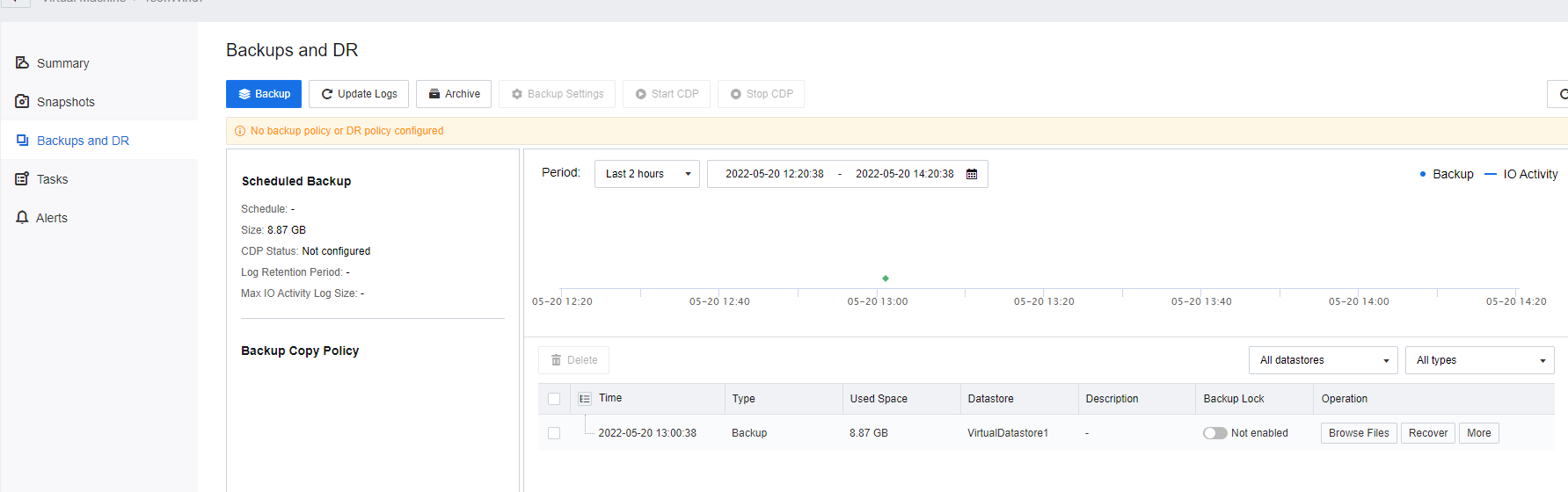
- Enable the DR Policy to perform incremental replication.
Note:
- For the first implementation of the Disaster Recovery, if the full backup data was massive (such as 100 TB level), the environment could not provide sufficient capacity for the disk. At this point, seed file transmission is not recommended. Instead, advise deploying the secondary site at the primary site location using the local network (up to gigabit or 10-gigabit interface) to complete the first DR full backup transmission. After the Backup is done, manually stop the DR Policy, move the secondary HCI cluster to the DR Site location, and enable the DR Policy again after DR site setup to perform subsequent incremental data replication.
- When the disk is mounted to the HCI, the disk will be formatted as Sangfor File System (SFFS). If there is data in the disk, back up the data in advance to avoid data loss.
- Before creating seed files, disable DR Policies to prevent the backup transfer and seed file import.
- After the USB device is inserted, HCI will identify and prompt to configure the USB. Since the disk is not for the use of VMs, there is no need to configure a USB. Turn off the prompt.
- The seed file is used for initial replication, and the DR Site must have no backup file on the respective VMs. Therefore, before importing the seed file, you are advised to delete the backup file of the placeholder VMs from the HCI of the DR Site.
- Exporting a seed file consists of two operations: Creating a seed backup file and exporting a seed file. Backup speed is manipulated to prevent services from being affected. Navigate to Reliability > Scheduled Backup/CDP > Settings to limit the VM backup speed at the primary site.
- For a VM with a small capacity (for example, less than 1TB), SSD can be used to save seed files during seed file creation and export to improve the export speed. For a mechanical disk with 8TB capacity (inserted on the server panel as local storage), the seed file’s rate is exported by about 100MB/s. The seed file is imported to the secondary site at about 50MB/s (for reference only).
Perform DR Test and Recovery
Protection Group
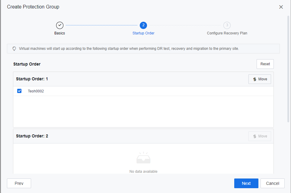
Adding VM into the Protection Group allows the SCP platform to perform disaster recovery based on the priority manner of the VM.
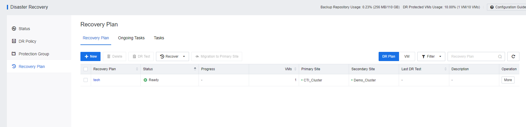
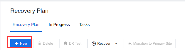
- Access to SCP portal, Navigate to Resources > Reliability > Disaster Recovery > Recovery Plan. Click New to create a recovery plan.
- Navigate to Resources > Reliability > Disaster Recovery > Protection Group, and click New to create the Protection Group.
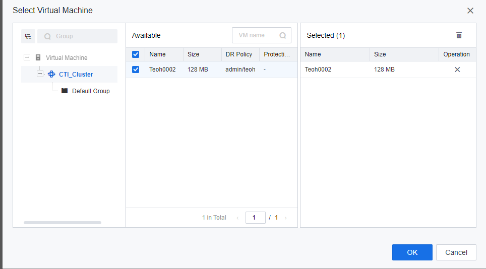
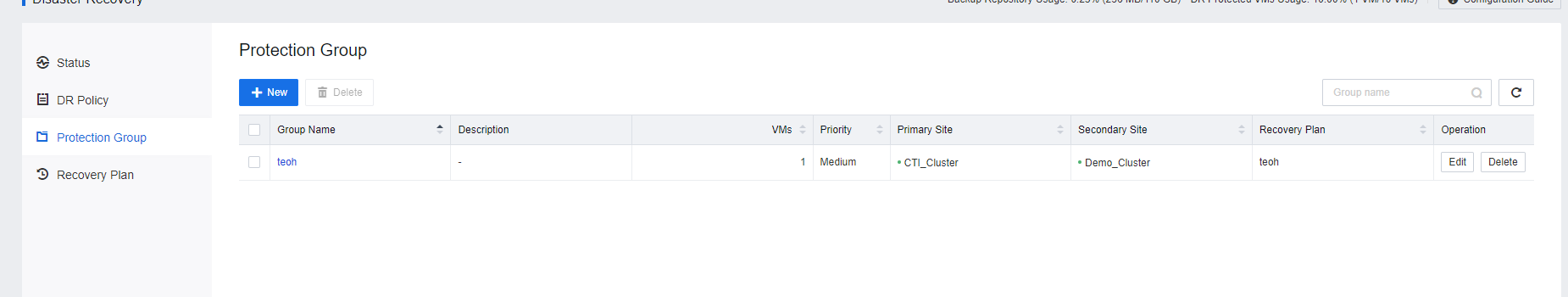
- VM has been successfully added to the Protection Group.
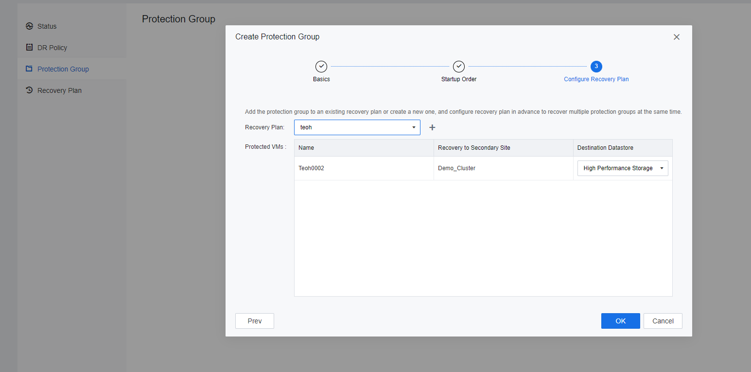
Configure Recovery Plan
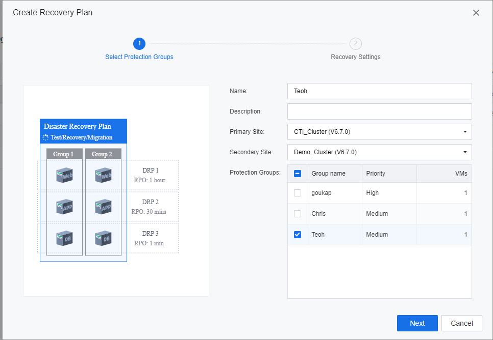
Based on the analysis of the business system and the general design, the DR plan shall be configured based on the environment. A recovery plan allows the user to group up the protection group together. The recovery plan will be executed and triggered based on the VMs protection group priority when performing disaster recovery activities on the selected recovery plan.
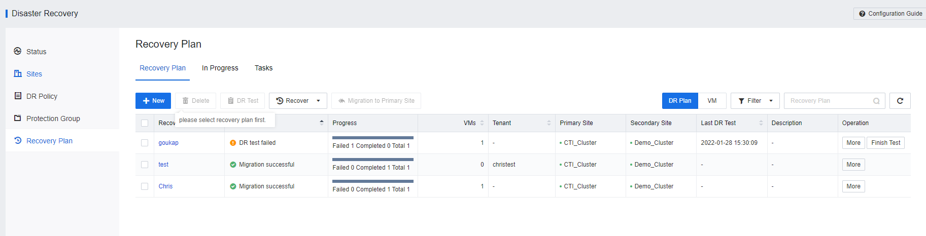
- Select Recovery Plan > New to create a new Recovery Plan.
- Generally, a service-related group can be added to a recovery plan for ease of management.
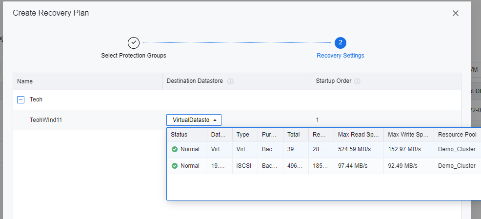
- Select a datastore to store the selected VM during the DR restoration.
Perform DR Test Before Disaster
Performing DR Test allows the user to verify the Primary Site and Secondary Site status to ensure the integrity and availability of DR Backup data. This activity was usually performed after the new DR policy creation and before the DR drill.
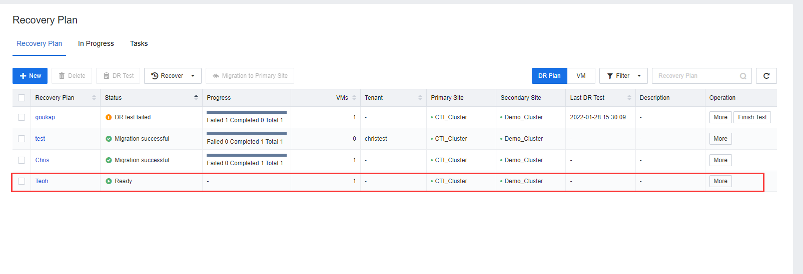
- On the SCP platform, navigate to Resources > Reliability > Disaster Recovery > Recovery Plan and select the respective Recovery Plan.
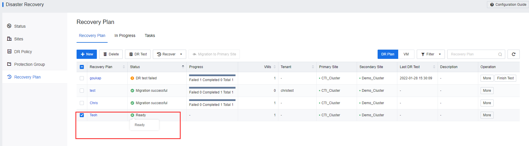
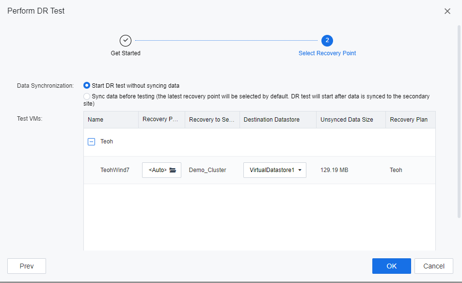
- Click DR Test to initiate the DR test process. Ensure the Full backup of the VM has been transmitted to the DR site before executing the DR test for the first time. Else SCP platform will not allow the user to initiate the DR Test.
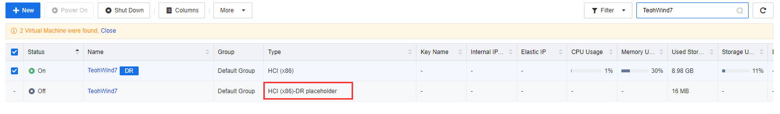
- On Recovery Plan, after the DR test is successfully executed, please navigate to the respective VM to check on its status. A newly created VM will be powered on as a placeholder VM instead of powering on the actual placeholder.
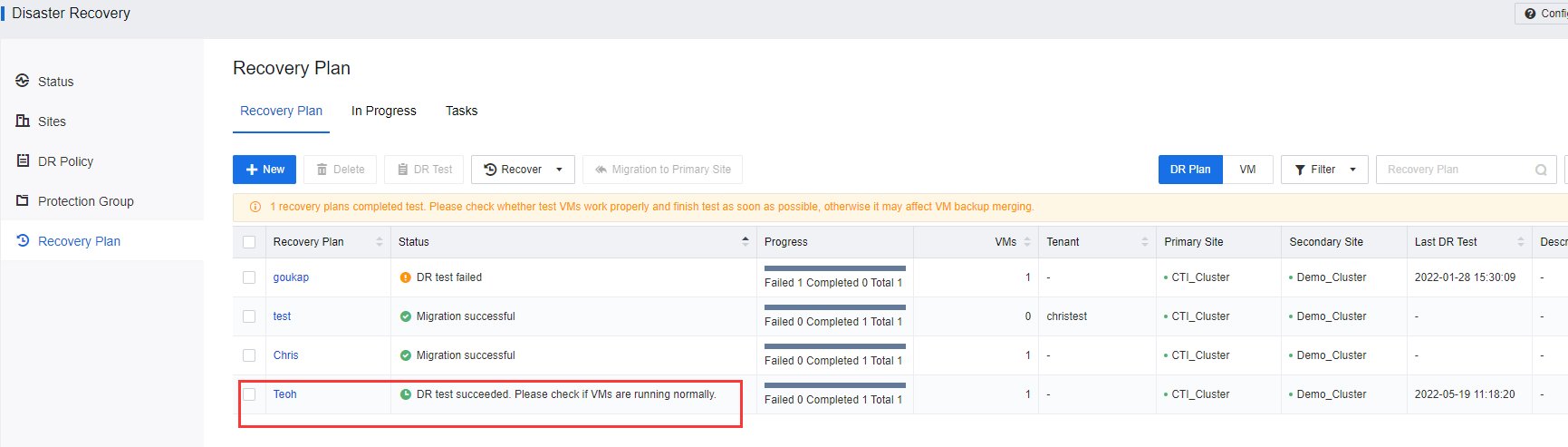
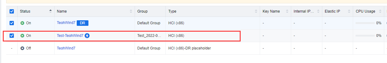
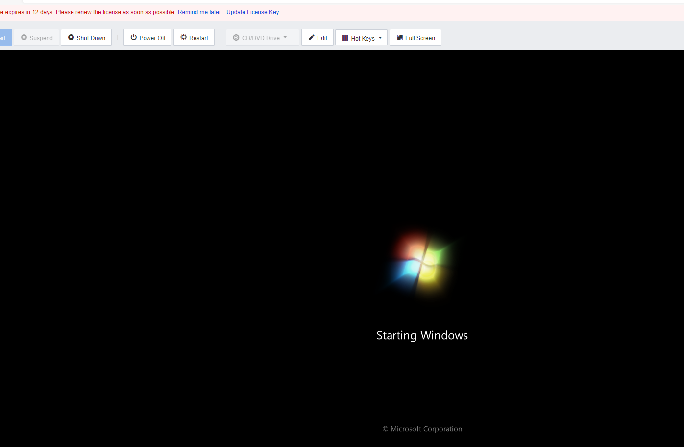
- Check the VM console and ensure the VM is working.
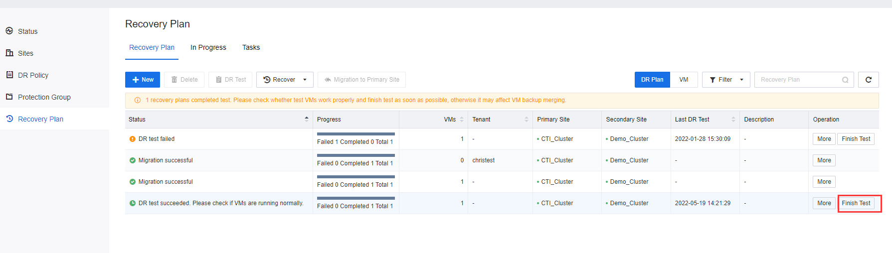
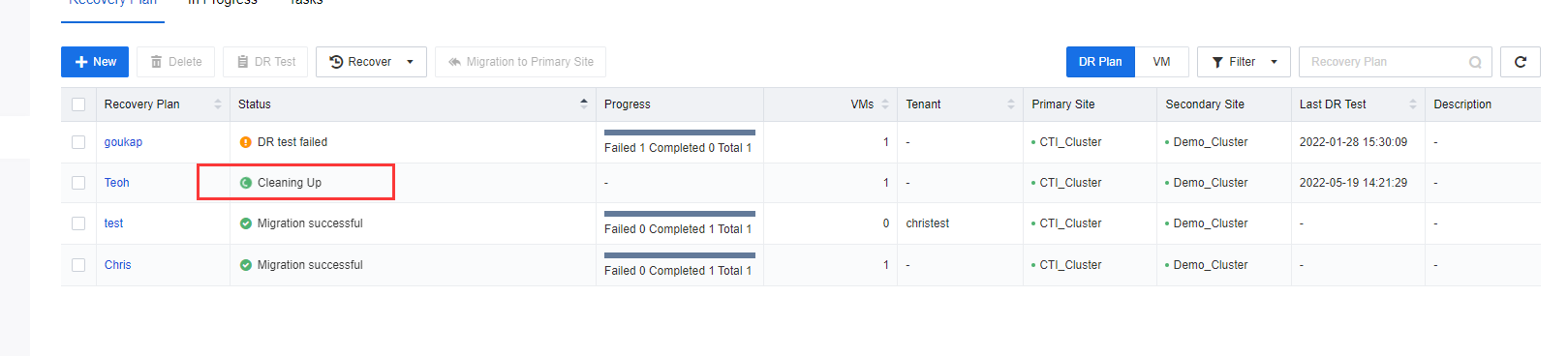
- After the DR Test is completed, click Finish Test on the respective recovery plan. The created testing VM will be automatically deleted after the test is completed.
Note:
- Ensure the VMs have been added to the DR Policy and generate full backup data.
- The hyper-converged cluster at the primary and secondary sites must be online.
- Make sure the DR Status of VMs is normal and meets RPO requirements. No backup, collation, or backup transmission task related to DR Is performed.
- DR Test starts a test VM at the secondary site. After the test VM is started, the user can verify the validity of DR Data and service availability.
- During the test, the VMs at the primary site will not be shut down or affected, and DR Data will continue to synchronize.
- The network connection between the drill site and the secondary site must be the same. The drill VMs is isolated from external networks. Therefore, service networks and normal running are not affected during the drill.
- The configurations of virtual network devices will not be replicated in the drill network and will be required to configure manually.
- The IP address of the VMs is the same as that of the DR Machine. If no IP address is configured for the DR Machine, the IP address must be the same as the VMs at the primary site.
- If a drill network fails to be automatically created, configure it manually.
DR Drill
Recover Business Services in the Event of Disaster
SCP Allows a running VM to switch from the primary site to the secondary site or switch back to the primary site. There are two types of Recovery modes to be selected based on the actual situation: Scheduled Recovery and Disaster Recovery.
Scheduled Recovery
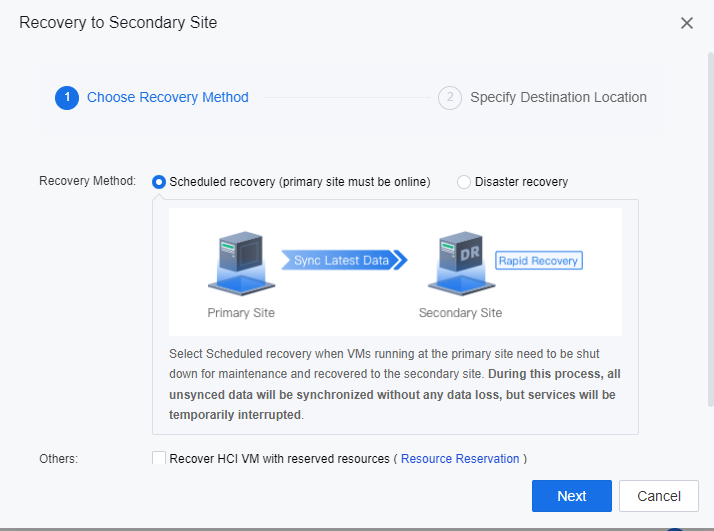
By using the option of scheduled recovery, all VMs’ unsynced data will be synchronized without any data loss, but services will be temporarily interrupted. Select this option when VMs running at the primary site need to be shut down for maintenance and recovered to the secondary site.
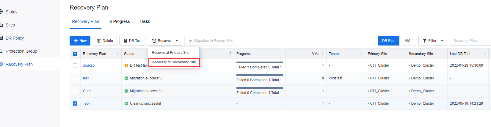
- Log in to the SCP platform, navigate to Resources > Reliability > Disaster Recovery > Recovery Plan, select the VMs and click Recovery to Secondary Site.
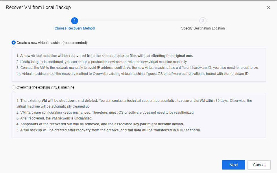
- In the displayed dialog box, select Disaster recovery and click Next.
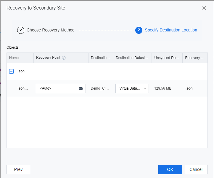
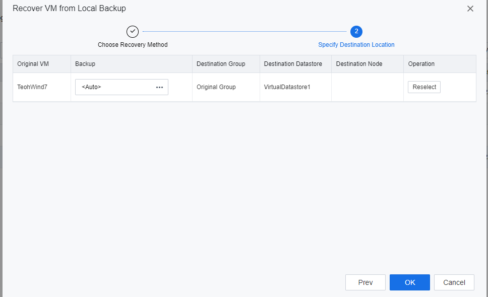
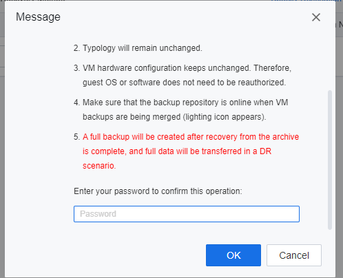
- Specify the datastore location for the DR placeholder VMs to be recovered, click OK, and enter the password of the user admin of the SCP platform on the prompted window to execute the DR recovery.
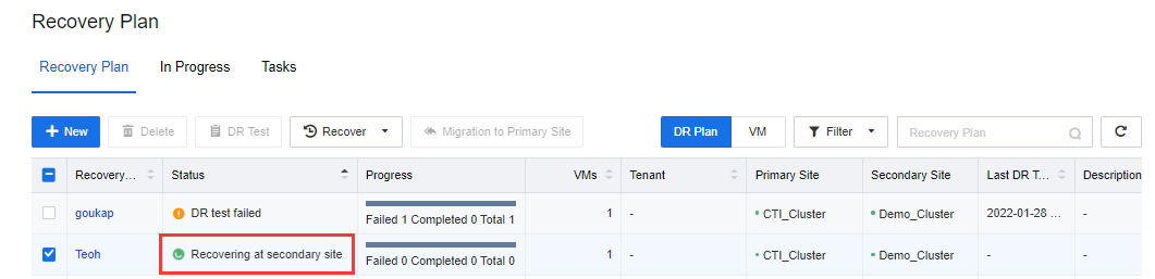
- The planned recovery is complete. Ensure that the VMs services Recovering at the secondary site are accessible and work normally.
Disaster Recovery
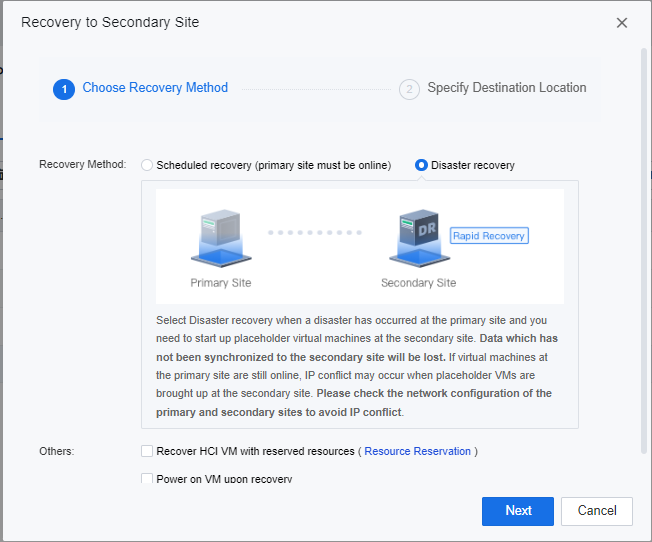
By selecting Disaster recovery, VMs data that has not been synchronized to the secondary site will be lost during the recovery activities. If virtual machines at the primary site are still online, IP conflict may occur when placeholder VMs are brought up at the secondary site. Select this method when a disaster has occurred at the primary site and are required to bring up placeholder virtual machines at the secondary site.
-
Log in to the SCP platform, navigate to Resources > Reliability > Disaster Recovery > Recovery Plan, select the VMs and click Recovery to Secondary Site.
-
In the displayed dialog box, select Disaster recovery and click Next.
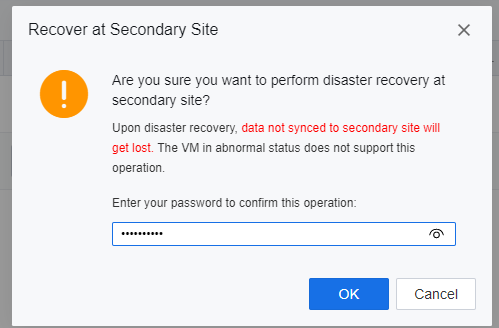
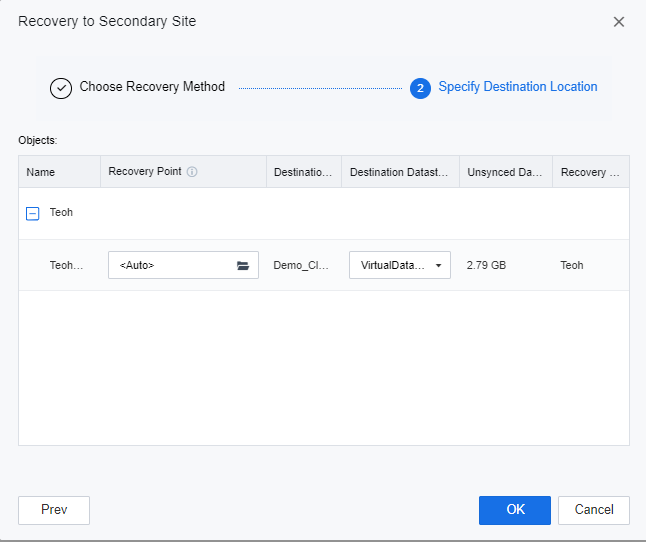
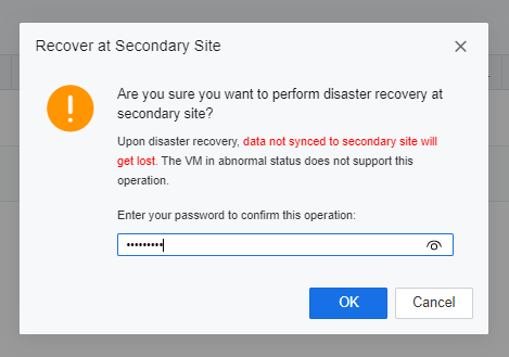
- Specify the datastore location for the DR placeholder VMs to be recovered, click OK, and enter the password of the user admin of the SCP platform on the prompted window to execute the DR recovery.
- Specify the datastore location for the DR placeholder VMs to be recovered, click OK, and enter the password of the user admin of the SCP platform on the prompted window to execute the DR recovery.
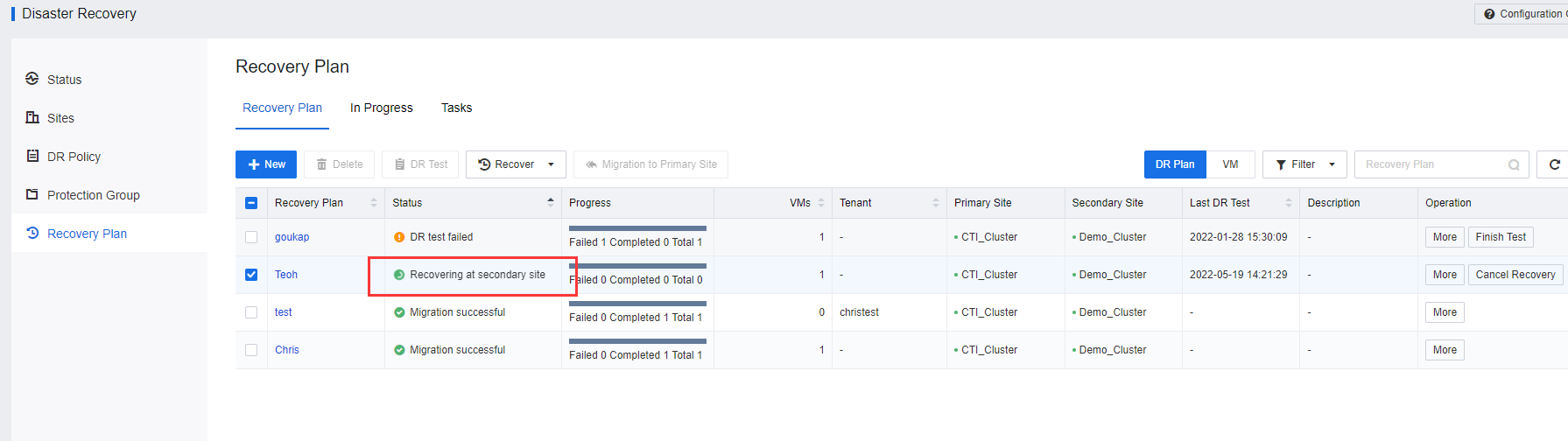
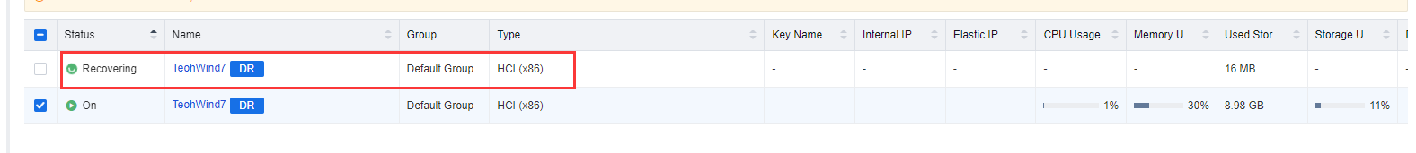
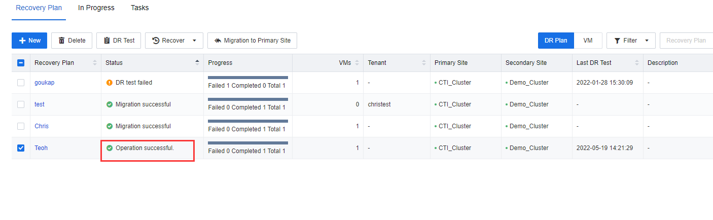
- The planned recovery will be shown on the Recovery plan list. Ensure that the VMs services Recovering at the secondary site are accessible and work normally.
Note:
- The VMs have been added to the DR Policy and generated full backup data.
- The hyper-converged cluster at the primary and secondary sites must be online.
- The DR Status of VMs is normal and meets RPO requirements. No backup, collation, or backup transmission task related to DR Is performed.
- Planned recovery will immediately shut down the VMs at the primary site, synchronizes the latest data to the secondary site, and automatically starts the DR Machine at the secondary site after the data synchronization is complete.
- When performing disaster recovery, evaluate and check the network configuration of the primary and secondary sites to avoid IP conflict.
- The connection between VMs and network egress must be planned in the network topology of the secondary site in advance.
- If an error occurs during the planned recovery, the recovery will be canceled.
- Acknowledge the business department and restore the targeted VMs on the secondary site after the primary site VM shuts down. While performing the VM restoration process on the secondary site will require the incremental backup data and placeholder VM to be ready. When the restoration process is ongoing, it will have a certain time of business interruption. It depends on the incremental data size, the network speed, and the primary site performances. Usually, an incremental backup size smaller than 10GB may require around 10 to 15 minutes for the restoration process.
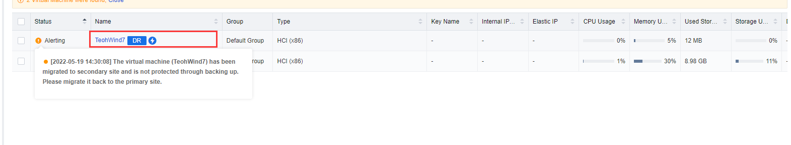
Notice:
After performing Disaster recovery or Scheduled/Local backup will stop as the DR VM has been powered off. The scheduled backup of the VM will be resumed after the VM is migrated back to Primary Site.
Migrate VM to Primary Site After Recovery
If a VM that has been restored to the secondary site needs to be switched back to the primary site, the user is able to recover back the VM to the primary site by using the Recover to Primary Site method.
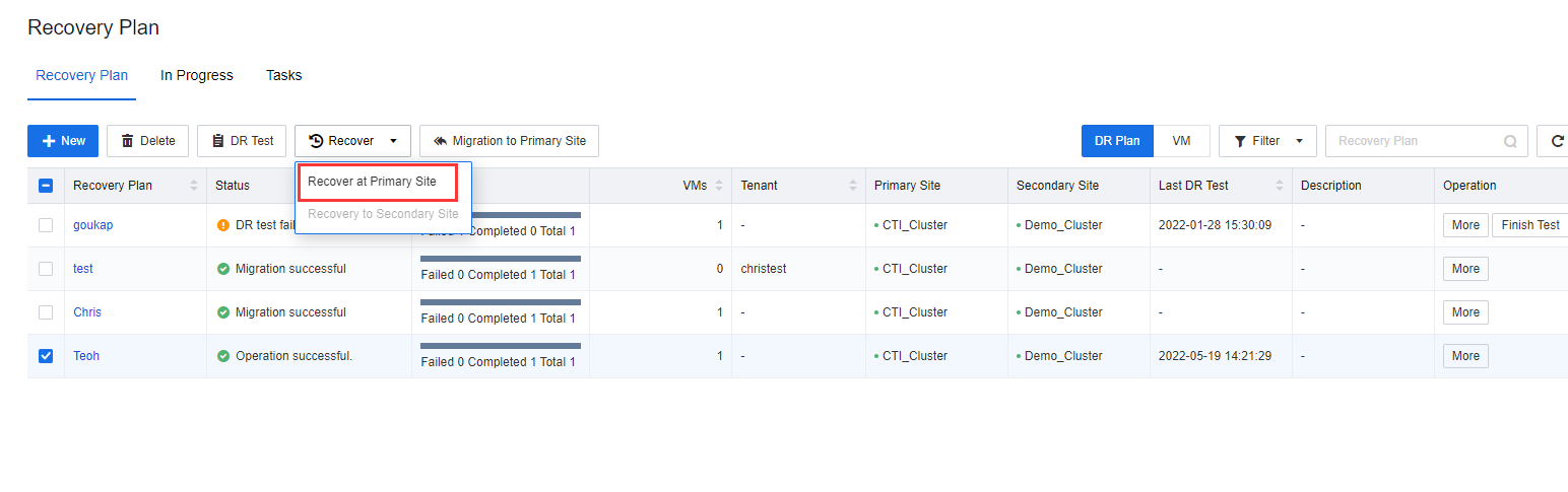
- Log in to the SCP platform, navigate to Resources > Reliability > Disaster Recovery > Recovery Plan, and select the VMs plan to perform the Recover task by clicking Recover > Recover to Primary Site.
- Select the datastore location of recovery to the primary site, click Next, and enter the password of the user admin of the SCP platform in the pop-up window.
-
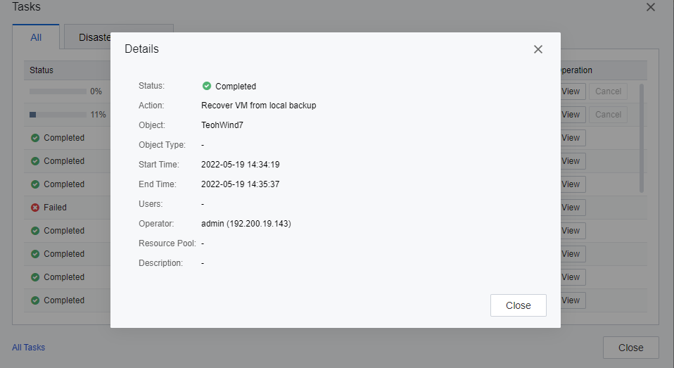
On the Tasks page, the user is able to review the VMs recover task. When the system is ready for recovery, access the secondary site, shut down the VMs to be migrated, and the failover will continue.
-
The planned failover is complete. Ensure that the VM services at the primary site are normal.
Note:
- The VMs at the secondary site has been restored to the DR Center.
- The cluster at the primary and secondary sites must be online.
- Ensure the DR Status of the VMs is normal and meets the RPO. No DR-related backup, collation, and backup transmission tasks are performed.
- Notify the service department that the VM participating in the planned migration will experience service interruption for about 30 minutes.
- After the incremental data at the secondary site is transferred to the primary site, manually stop the VM at the secondary site. When the SCP detects that the VM at the secondary site is shut down, the SCP performs the last data synchronization and continues to restore data.
- During the planned migration, services will be interrupted for about 30 minutes.
- If any error occurs in the migration process to the primary site, the task will be canceled.